Panasonic WX-H3050 Manuel utilisateur
- Catégorie
- Écouteurs
- Taper
- Manuel utilisateur
Ce manuel convient également à

WX-H3050
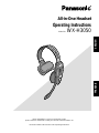
All-in-One Headset
Operating Instructions
Model No. WX-H3050
Before attempting to connect or operate this product,
please read these instructions carefully and save this manual for future use.
No model number suffix is shown in this Operating Instructions.
ENGLISHFRANÇAIS

2
FEDERAL COMMUNICATIONS COMMISSION INTERFERENCE STATEMENT
This equipment has been tested and found to comply with the limits for a Class A digital device, pursuant to part 15 of the
FCC Rules. These limits are designed to provide reasonable protection against harmful interference when the equipment is
operated in a commercial environment. This equipment generates, uses, and can radiate radio frequency energy and, if not
installed and used in accordance with the instruction manual, may cause harmful interference to radio communications.
Operation of this equipment in a residential area is likely to cause harmful interference in which case the user will be
required to correct the interference at his own expense.
FCC Warning: This transmitter must not be co-located or operated in conjunction with any other antenna or transmitter.
FCC Warning: The available scientific evidence does not show that any health problems are associated with using low
power wireless devices. There is no proof, however, that these low power wireless devices are absolutely safe. Low power
wireless devices emit low levels of radio frequency energy (RF) in the microwave range while being used. Whereas high lev-
els of RF can produce health effects (by heating tissue), exposure to low-level RF that does not produce heating effects
causes no known adverse health effects. Many studies of low-level RF exposures have not found any biological effects.
Some studies have suggested that some biological effects might occur, but such findings have not been confirmed by addi-
tional research. WX-H3050 has been tested and found to comply with FCC radiation exposure limits set forth for an uncon-
trolled equipment and meets the FCC radio frequency (RF) Exposure Guidelines in Supplement C to OET65.
FCC Warning: To assure continued FCC emission limit compliance, use only the provided power supply cord and shielded
interface cable when connecting this device to the computer. Also, any unauthorized changes or modifications to this equip-
ment would void the user's authority to operate this device.
This device complies with Part 15 of the FCC Rules. Operation is subject to the following two conditions: (1) This device
may not cause harmful interference, and (2) this device must accept any interference received, including interference that
may cause undesired operation.
Responsible Party: Panasonic Corporation of North America
One Panasonic Way, Secaucus, NJ 07094
Technical Support Party: Panasonic Consumer Electronics Company
1707 N. Randall Rd., Elgin IL. 60123
Technical Support Tel No.: 886-472-6767
The model number and serial number of this product may be
found on the surface of the unit.
You should note the model number and serial number of this
unit in the space provided and retain this book as a perma-
nent record of your purchase to aid identification in the event
of theft.
Model No.
Serial No.
For U.S.A.
For U.S.A.
RSS-213
Operation is subject to the following two conditions: (1) this
device may not cause interference, and (2) this device must
accept any interference, including interference that may cause
undesired operation of the device.
CAUTION:
• Danger of explosion if battery is incorrectly replaced. Replace
only with the same or equivalent type.
• These servicing instructions are for use by qualified service per-
sonnel only. To reduce the risk of electric shock do not perform
any servicing other than that contained in the operating instruc-
tions unless you are qualified to do so.
For Canada
ENGLISH VERSION
CAUTION
The FCC ID number for this radio equipment is listed below.
FCC ID: ACJ9TAWX-H3050
For U.S.A.
ICES-003
This Class A digital apparatus complies with Canadian ICES-003.
For Canada

3
WARNING:
• This apparatus must be earthed.
• Apparatus shall be connected to a main socket outlet with a pro-
tective earthing connection.
• The mains plug or an appliance coupler shall remain readily
operable.
• To reduce the risk of fire or electric shock, do not expose this
apparatus to rain or moisture.
• The apparatus should not be exposed to dripping or splashing
and that no objects filled with liquids, such as vases, should be
placed on the apparatus.
• All work related to the installation of this product should be made
by qualified service personnel or system installers.
• To prevent injury, this apparatus must be securely attached to
the floor/wall in accordance with the installation instructions.
• The connections should comply with local electrical code.
• The risk of hearing impairment due to exposure to excessive
sound levels may be reduced by listening at lower volumes and
for shorter durations.
ATTENTION:
A lithium-ion battery that is recyclable powers the prod-
uct you have purchased. Please call 1-800-8-BATTERY
for information on how to recycle this battery.
Limitation of Liability
THIS PUBLICATION IS PROVIDED "AS IS" WITHOUT WARRANTY OF ANY KIND, EITHER EXPRESS OR IMPLIED, INCLUDING
BUT NOT LIMITED TO, THE IMPLIED WARRANTIES OF MERCHANTABILITY, FITNESS FOR ANY PARTICULAR PURPOSE, OR
NON-INFRINGEMENT OF THE THIRD PARTY'S RIGHT.
Disclaimer of Warranty
IN NO EVENT SHALL MATSUSHITA ELECTRIC INDUSTRI-
AL CO,. LTD. BE LIABLE TO ANY PARTY OR ANY PERSON,
EXCEPT FOR REPLACEMENT OR REASONABLE MAINTE-
NANCE OF THE PRODUCT, FOR THE CASES, INCLUDING
BUT NOT LIMITED TO BELOW:
(1) ANY DAMAGE AND LOSS, INCLUDING WITHOUT LIMI-
TATION, DIRECT OR INDIRECT, SPECIAL, CONSE-
QUENTIAL OR EXEMPLARY, ARISING OUT OF OR
RELATING TO THE PRODUCT;
(2) PERSONAL INJURY OR ANY DAMAGE CAUSED BY
INAPPROPRIATE USE OR NEGLIGENT OPERATION OF
THE USER;
(3) UNAUTHORIZED DISASSEMBLE, REPAIR OR MODIFI-
CATION OF THE PRODUCT BY THE USER;
(4) ANY PROBLEM, CONSEQUENTIAL INCONVENIENCE,
OR LOSS OR DAMAGE, ARISING OUT OF THE SYSTEM
COMBINED BY THE DEVICES OF THIRD PARTY.
ENGLISH

4
Important Safety Instructions
1) Read these instructions.
2) Keep these instructions.
3) Heed all warnings.
4) Follow all instructions.
5) Do not use this apparatus near water.
6) Clean only with dry cloth.
7) Do not block any ventilation openings. Install in accordance with the manufacturer's instructions.
8) Do not install near any heat sources such as radiators, heat registers, stoves, or other apparatus (including amplifiers) that
produce heat.
9) Do not defeat the safety purpose of the polarized or grounding-type plug. A polarized plug has two blades with one wider
than the other. A grounding type plug has two blades and a third grounding prong. The wide blade or the third prong are
provided for your safety. If the provided plug does not fit into your outlet, consult an electrician for replacement of the obso-
lete outlet.
10) Protect the power cord from being walked on or pinched particularly at plugs, convenience receptacles, and the point
where they exit from the apparatus.
11) Only use attachments/accessories specified by the manufacturer.
12) Use only with the cart, stand, tripod, bracket, or table specified by the manufacturer, or sold with the apparatus. When a cart
is used, use caution when moving the cart/apparatus combination to avoid injury from tip-over.
13) Unplug this apparatus during lightning storms or when unused for long periods of time.
14) Refer all servicing to qualified service personnel. Servicing is required when the apparatus has been damaged in any way,
such as power-supply cord or plug is damaged, liquid has been spilled or objects have fallen into the apparatus, the appa-
ratus has been exposed to rain or moisture, does not operate normally, or has been dropped.
S3125A

5
Limitation of Liability ................................................................................................................................... 3
Disclaimer of Warranty ............................................................................................................................... 3
Important Safety Instructions ...................................................................................................................... 4
Preface ....................................................................................................................................................... 6
Features ...................................................................................................................................................... 6
Precautions ................................................................................................................................................. 6
Major Operating Controls and Their Functions ........................................................................................... 7
Battery Loading & Replacement ................................................................................................................ 9
■ Installation ............................................................................................................................................ 9
■ Loading ................................................................................................................................................ 9
■ Replacement ........................................................................................................................................ 9
Operating Procedures ................................................................................................................................ 10
■ Preparations ......................................................................................................................................... 10
■ Communications with Customers [TALK] ............................................................................................. 11
■ Communications with Other Store Personnel [PAGE] .......................................................................... 11
■ Control of the device control terminals ................................................................................................. 12
■ Double-Drive-Thru connections ........................................................................................................... 12
■ Manager Mode (Only one headset) ..................................................................................................... 13
■ Canceling the Manager Mode ............................................................................................................. 13
■ Auto-Talk-Lock setup (for only one headset) ....................................................................................... 14
Maintenance ............................................................................................................................................... 15
Setup Procedures ....................................................................................................................................... 16
■ Opening the Switch Compartment ....................................................................................................... 16
■ DIP Switch Setup .................................................................................................................................. 16
■ ID Registration ...................................................................................................................................... 17
■ Deletion of ID ....................................................................................................................................... 17
Troubleshooting........................................................................................................................................... 18
Specifications ............................................................................................................................................. 19
Standard Accessories ................................................................................................................................ 20
Optional Accessories ................................................................................................................................. 20
CONTENTS

6
Preface
All-in-One Headset WX-H3050 is exclusively designed for Panasonic Wireless Communication System, which is used with drive-
thru menu boards, etc. This headset is equipped with the microphone, earphone as well as battery compartment and control
buttons. With the built-in antennas, transmitter, and receiver, users can communicate with other store personnel and customers.
Features
• This headset can be used with Center Module WX-C3010.
• 1.9 GHz DECT* is used with headset to prevent the interference from microwave ovens or wireless LAN used with 2.4 GHz
DECT.
* Digital Enhanced Cordless Telecommunications
• Manager mode
It is possible to set the manager mode to one of the headsets registered in the center module. A person using this headset
has the priority of communication.
• When the Auto Talk Lock function is activated, With the Auto Talk Lock function, users can communicate with customers
without holding down the button.
• When a customer approaches the menu board, this headset automatically enters the Auto Talk Lock mode.
• It is possible to use voice prompt to check the settings of headset.
• When using this headset in the double-drive-thru system, it is possible to communicate without changing the lane setting.
• It is possible to select Direct Lane or A/B Lane according to double-drive-thru layouts.
• It is possible to select the Talk-Lock or Press-To-Talk mode.
• It is possible to select the Page-Lock or Press-To-Page mode.
• Headpad cushion and earphone cushion is easy to be replaced.
Precautions
• Use only Battery WX-B3030.
• Follow the instructions of battery for care and handling.
• In combination with this product, refer to Battery Charger WX-Z3040 Operating Instructions.
• Use the headset with the earphone pad attached. Otherwise, voice may become distorted or you may have difficulty in hear-
ing the voice.
• Turn off the headset when not in use, in order to save the battery life.
• Do not use this product if you use an implanted electric medical equipment. That may cause the equipment to malfunction.

7
t
y
u
r
i
o
e
q
w
!0
!2
!4
!1
!3
!5
!6
!7
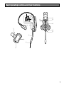
Major Operating Controls and Their Functions

8
q Head Band and Head Pad
Adjustable to your head by sliding the head pad.
w Battery Lock [EJECT]
When removing the battery, slide out the lock.
When loading a battery, insert the battery until the lock
clicks.
e Battery Case / Battery (Optional accessory)
Refer to p. 6 "Precautions".
r Head Pad Cushion
t Switch Compartment
Do not open the cover of this compartment. It should be
opened only by qualified service personnel or system
installers.
y Power Button [POWER]
Pressing the button will turn the headset on.
Pressing the button again for 2 seconds or more will turn
the headset off.
u Earphone Pad
i Microphone Boom
Adjust the microphone position to your mouth by rotating
and bending the boom.
o Microphone
!0 Lane Indicator
Lights yellow or green to indicate which the lane is in
operation.
Yellow: Lane A is selected.
Green: Lane B is selected.
Yellow blinking: Lane A is being selected, and either
the Talk or Page mode is activated.
Green blinking: Lane B is being selected, and either
the Talk or Page mode is activated.
!1 Power Indicator
The indicator shows the status as follows.
Green: Power is supplied and the unit is operating.
Green blinking: Power is supplied and Manager mode
is activated.
Red: The battery requires recharging.
Red blinking: ID is not registered, or the center module
is set to the ID Registration mode.
!2 Optional Function Button [R]
This button is intended for functional extension.
When the All-in-One Headset is set in the manager
mode and this button is pressed, operation cannot be
forwarded for talking or paging. At that time, the
Telephone Indicator of the Center Module lights.
To recover the talk or page operation, press this button
again.
The Telephone Indicator is turned OFF and the talk and
page operation becomes possible.
!3 External Device Control Button [C]
Press and hold the C button to turn on the external
device.
!4 Volume Control Buttons [VOL
!@
]
Pressing the buttons will increase or decrease the sound
level.
!5 Talk 1 Button [T1]
This button controls communications with the customer.
When the button is released, you can hear any customer
who is at the menu-board.
While the button is held down in the Press-To-Talk
mode, you can speak to the customer.
When the button is pressed in the Talk-Lock mode, you
can speak to the customer until you press the button a
second time.
!6 Talk 2 / A/B Lane Selection Button [T2, A/B]
This button can be set to two functions by the DIP switch
setting. (Refer to p.16 "DIP Switch Setup".)
[T2]
This button controls communications with the customer
on lane B of double-drive-thru.
When the button is released, you can hear any customer
who is at the menu board.
While the button is held down in the Press-To-Talk
mode, you can speak to the customer who is at the
menu board.
When the button is pressed in the Talk Lock mode, you
can speak to the customer until you press the button a
second time.
[A/B]
This button switches from Lane A to B and vice versa.
The Lane indicator !0 displays the selected Lane in yel-
low (A) or green (B).
!7 Page Button [P]
This button controls communications with store person-
nel.
When the button is released, you can hear the communi-
cations among store personnel.
While the button is held down in the Press-To-Page
mode, you can speak to store personnel.
When the button is pressed in the Page-Lock mode, you
can speak to the store personnel until you press the but-
ton a second time.

9
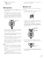
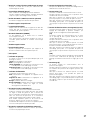
Notes:
• Refer to operating instructions included with the battery
and battery charger.
• Battery replacement is recommended when the power
indicator lights up in red and a pulsing beep is heard in
the headphone.
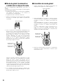
■ Installation
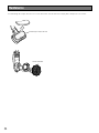
1. Insert the battery in the battery case as shown in the fig-
ure.
■ Loading
1. Prepare a fully charged battery.
2. Insert the battery as shown in the figure.
Note: Be sure to insert it until the lock clicks.
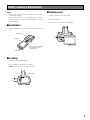
■ Replacement
1. Slide the battery lock to the outside.
2. Remove the battery.
3. Proceed as described in "Loading" above.
q
w
e
Battery Case
q
w
Battery Case
Battery Case
Battery
Terminal
Battery Loading & Replacement
When inserting the battery,
check the positive and
negative sides.

10
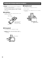
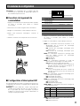
■ Preparations
Prior to operating the headset, confirm that the system setup
for the headset, center module, and other devices has been
completed.
1. Install a battery in the battery compartment. Refer to p. 9
Battery Loading & Replacement.
2. Press the power button to turn on the headset.
3. Wear the headset.
4. Adjust the head pad so that the earphone is placed on
your ear.
5. Rotate and bend the microphone boom so that the
microphone is placed near your mouth.
6. Attach a strap or the head protectors (provided) if nec-
essary.
Use a strap that meets the following conditions.
• A commercially available strap is attachable.
• Width of string is 9 mm {11/32"} or more.
• The strap has a joint and is designed to go off when
hung up on the structure.
The provided head protector is attachable.
Strap (locally procured)
Head protectors
(provided)
q
w
e
Power button
Operating Procedures

11
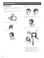
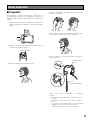
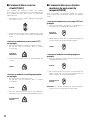
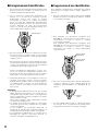
■ Communications with
Customers [TALK]
Any store personnel wearing the headset can communicate
bidirectionally with any customer who is at the menu board.
1. Select a proper sound level by pressing the ! or @ but-
ton.
2. You will hear a beep in the headset when a vehicle
arrives at the menu board.
<When the Press-To-Talk (PTT) mode is pre-
set>
1. Hold down the T1 button and speak to the customer.
A short beep is heard in the headset.
2. Release the button. Your voice is not heard by the cus-
tomer.
<When the Talk-Lock mode is preset>
1. Press the T1 button and speak to the customer.
A short beep is heard in the headset.
2. Press the button again. The lock is released, and your
voice is not be heard by the customer.
■ Communications with Other
Store Personnel [PAGE]
Store personnel wearing the headset can communicate with
each other without being heard by customers.
<When the Press-To-Page (PTP) mode is pre-
set>
1. Hold down the P button and speak into the microphone
at a normal level.
2. Release the button. Your voice will not be heard by the
other store personnel.
<When the Page-Lock mode is preset>
1. Press the P button and speak into the microphone at a
normal level.
2. Press the P button again. The lock will be released, and
your voice will not be heard by the other store person-
nel.
Note: A maximum of 4 operators can have a conversation at
the same time.
Press
Hold down
Release
Press
Press again
Hold down
Release
Press again

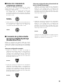
■ Control of the device control ter-
minals
The device control terminals of the center module can be
controlled through the headset.
1. Hold down the C button. A short beep is heard from the
speaker of the headset and a connection will be made
toward the device control terminals of the center mod-
ule.
2. Release the C button. A short beep is heard twice from
the speaker of the headset and the connection will be
disconnected toward the device control terminals of the
center module.
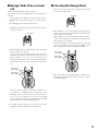
■ Double-Drive-Thru connections
When Double-Drive-Thru connections are made with the
center module, any headset is required to select the center
module of either Lane A or Lane B.
<For Normal setup>
1. When a connection is made to Lane A, the lane indicator
is lit in yellow. Press the T2 button if you want to make a
connection changeover to Lane B. When connected to
Lane B, a voice of [Lane B] is heard from the speaker of
the headset and the lane indicator is lit in green.
2. While a connection is maintained to Lane B, the lane
indicator is lit in green. Press the T2 button if you want to
make a connection changeover to Lane A. When con-
nected to Lane A, a voice of [Lane A] is heard from the
speaker of the headset and the lane indicator is lit in yel-
low.
<For Direct Lane Select setup>
1. While a connection is maintained to Lane A, the lane
indicator is lit in yellow. Press the T2 button if you want
to make a connection changeover to Lane B. When con-
nected to Lane B, a voice of [Lane B] is heard from the
speaker of the headset and the lane indicator is lit in
green.
2. While a connection is maintained to Lane B, the lane
indicator is lit in green. Press the T1 button if you want to
make a connection changeover to Lane A. When con-
nected to Lane A, a voice of [Lane A] is heard from the
speaker of the headset and the lane indicator is lit in yel-
low.
When Direct Lane Select is set, TALK is available by
selecting either lane pressing T1 or T2 button.
12
Press
Hold down
Press
Press
Press
Release

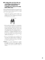
13
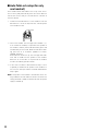
■ Manager Mode (Only one head-
set)
Complete ID Registration, to do this setting.
The headset set to the Manager mode has following func-
tionality.
• The manager can interrupt store personnel's TALK or
PAGE at any time by monopolizing one channel by prior-
ity.
• The Manager hears audio from POS alone.
1. Hold down the power button for two seconds or more to
turn off the headset.
2. While holding R and T1 simultaneously, press the power
button to turn on the headset.
The headset enters manager setting mode where the
indicators and buttons have different functions than in
normal operation. You can hear "Connecting center
module A" and power indicator is an alternate blinking of
red and green. Also the Lane indicator A is blinking yel-
low.
When you want to register the manager in another cen-
ter module in a double-drive-thru environment, while
holding R and T2 simultaneously, press the power but-
ton to turn on the headset. You can hear "Connecting
center module B" and the power indicator blinks red and
green. Also the Lane indicator B blinks green.
3. If manager mode setting is successful, you can hear
"Manager" and the power indicator blinks green.
■ Canceling the Manager Mode
1. Turn off the power of All-in-One Headset that has been
set for the manager mode.
2. When LANE A is set in the manager mode, keep press-
ing the R and T1 buttons simultaneously and start up the
power of All-in-One Headset.
When LANE B is set in the manager mode, keep press-
ing the R and T2 buttons simultaneously and start up the
power of All-in-One Headset.
The power indicator then blinks reciprocally in red and
green. A message of "Connecting Center Module A (or
B)" is heard from the All-in-One Headset speaker.
3. When canceling of the manager mode is complete, reci-
procal blinking of the power indicator turns to continu-
ous lighting in green.
Keep holding
down (LANE A)
Keep holding
down (LANE B)
Power button
Power button
Keep holding
down (LANE A)
Keep holding
down (LANE B)

14
■ Auto-Talk-Lock setup (for only
one headset)
For a headset where Auto-Talk-Lock is set up, it has a func-
tion to select [Talk] automatically when the vehicle detector
has become active, and you can talk with the customer at
the menu board.
1. Confirm that the DIP Switch 1 of the headset is ON, the
DIP Switch 2 is set at the objective lane, and the power
of the headset is OFF.
2. Turn on the headset. The message "Hello Headset **" (**
is the number of headset) is output from the speaker of
the headset, and the power indicator blinks green and
red alternately for 3 seconds. While the indicator is blink-
ing, press the T1 or T2 button. (LANE A: T1 button,
LANE B: T2 button)
Auto-Talk-Lock will be set up, The message "Auto-Talk-
Lock ON" is heard from the speaker of the headset.
When the T1 or T2 button is not pressed, the headset
assumes an ordinary operation mode.
3. In the case of a failure in Auto-Talk-Lock setup, a voice
of [Failed] is heard from the speaker of the headset. In
this case, the same procedures should be followed from
Step 1 again.
Note: If the power of the headset is turned OFF, all the set-
ting conditions for Auto-Talk-Lock will be canceled. This
setting should be carried out without fail when the power
supply is started up.
Power button

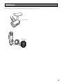
15
The head-pad cushion and earphone-pad are replaceable. Replace when necessary.
Head-pad cushion
Earphone-pad
Maintenance

16
Caution: Setup of this product should only be performed by
qualified service personnel or system installers.
■ Opening the Switch
Compartment
1. Press the power button for 2 seconds or more to turn off
the headset.
2. Unscrew the screw and open the switch compartment.
3. Set the switches as described below.
4. After finishing the setup, replace the cover.
5. Turn on the headset.
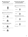
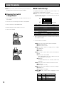
■ DIP Switch Setup
An eight-bit DIP switch is provided for system setups. The
initial setting is marked with an asterisk *.
Note: Be sure to turn off the headset in Step 1. Otherwise,
the DIP Switch will not be activated until you turn the
power off and on again.
1. Press the power button for 2 seconds or more to turn off
the headset. headset.
2. Set the switches as follows.
SW#1: This switch selects Auto Talk Lock ON/OFF
ON: Auto Talk Lock ON
OFF: Auto Talk Lock OFF
SW#2: This switch selects the target lane for "SW#1:
Auto Talk Lock".
ON: Lane B
OFF: Lane A
SW#3: This switch selects Direct Lane Select Mode or
Normal.
ON: Direct Lane Select Mode
When double-drive-thru, the T1 button is for lane
A, the T2 button is for lane B.
OFF: Normal
For double-drive-thru, the T2 button is A/B Lane
Selection.
SW#4: This switch selects Talk Lock or Press-To-Talk
ON: Talk Lock
OFF: PTT (Press-To-Talk)
SW#5: This switch selects Page Lock or Press-To-Page.
ON: PAGE Lock
OFF: PTP (Press-To-Page)
SW#6, SW#7: This switch selects language of Voice
Prompt.
Setup Procedures
1
SW#
2
3
4
5
6
7
8
Auto TALK Lock ON/OFF
Function
Voice Prompt Language Select
Voice Prompt Language Select
ON
ON
OFF*
OFF
Auto TALK Lock LANE B A*
T2 Button Setting Direct Lane Select Normal*
Talk Lock/Press-To-Talk TALK Lock PTT*
Page Lock/Press-To-Page PAGE Lock PTP*
RF Power Reduce Power Full Power*
1
2
3
4
5
6
7
8
Initial Setting
ON
OFF
SW#6
OFF*
OFF
ON
ON
OFF*
ON
OFF
ON
English
Spanish
French
Voice Prompt OFF
SW#7 Language

17
SW#8: This switch selects RF Power.
ON: Reduce Power
OFF: Full power
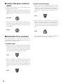
■ ID Registration
1. Press the ID Registration of the center module for 2 sec-
onds or more. The system is changed to the ID
Registration mode.
2. While holding down the T1 and T2 buttons simultaneous-
ly, hold down the power button to turn on the headset.
The headset enters the ID Registration setting mode
where the indicators and buttons have different func-
tions than in normal operation. You will hear "ID
Registration Mode" and the power indicator will blink yel-
low.
3. Press the T1 button, the headset searches for the center
module. You can hear "Connecting center module A"
and the lane Indicator will blink yellow.
* Press the T2 button (at double-drive-thru), for other cen-
ter modules. You can hear "Connecting center module
B" and the lane indicator will blink green.
When the ID Registration succeeds, you will hear
"Registration complete" and the headset number, and
the power indicator stops blinking and stays on.
4. When IDs are registered on all headsets, press the ID
Registration button of the center module, ID registration
mode is completed. The power indicator of the headset
will change from yellow to green.
Notes:
• If ID registration fails, a warning sounds "beep" and then
you will hear a voice prompt say "Failed". If registration
fails, the ID is not registered and the "Power" indicator
blinks red.
If this happens, turn off the power and try registering
again.
• All-in-One Headset or Order Taker that can register in
one center module is up to 32.
If you register IDs exceeding 32, the unused ID that has
been registered is automatically deleted in chronological
order.
• If ID registration is performed for 2 or more headsets,
follow the steps 2-4 individually.
■ Deletion of ID
To delete the registered ID of All-in-One Headset, follow the
steps below.
1. Hold down the POWER button for more than 2 seconds
to turn off the power of All-in-On-Headset.
2. To delete an ID that is registered for LANE A, keep
pressing the T1 and C buttons simultaneously and start
up the power of All-in-One Headset.
To delete an ID that is registered for LANE B, keep
pressing the T2 and C buttons simultaneously and start
up the power of All-in-One Headset. The power indicator
then blinks in yellow.
3. Press the P button while the power indicator keeps blink-
ing in yellow. The ID that is registered for LANE A (or
LANE B) is deleted.
4. The power indicator turns to blinking in red. A message
of "ID is not registered" is heard from the All-in-One
Headset speaker.
Power button
Keep holding
down (LANE A)
Keep holding
down (LANE B)
Keep holding
down
Keep holding
down

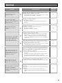
18
The headset ID is not registered in the center module of the tar-
get.
→ Register ID in the center module of the target.
The battery is almost exhausted.
→ Recharge the battery.
(Refer to the operating instructions of the battery charger.)
The center module may be turned off.
→ Turn on the power switch of the center module. (Refer to the
operating instructions of the center module.) If no remedy
exists, consult your dealer for repairs.
The headset ID is not registered in the center module of the tar-
get.
→ Register ID in the center module of the target.
The vehicle detector may be malfunctioning because the detec-
tor is not plugged into the center module, no power is supplied,
or the detecting function is out of order.
→ Check that the vehicle detector is plugged in and has power.
(Refer to the operating instructions of the center module.)
If no remedy exists, consult your dealer for repairs.
Radio waves cannot reach the area.
→ Remove any metal obstacles blocking radio waves.
Check that the Telephone Indicator of the Center Module is not
turned ON.
If the indicator is turned ON, the Optional Function Button [R] is
turned ON.
→ Press the Optional Function Button [R] again and check that
the Telephone Indicator is turned OFF.
Reference
pages
Cause/solution
17
–
–
17
–
–
8
Symptom
The power indicator blinks red.
The power indicator lights red
and a constant beep is heard in
the headphone.
Cannot communicate with other
store personnel or the customer
at the menu board.
Cannot hear or talk to the cus-
tomer, but communications with
the store personnel are OK.
Cannot "page" or "talk" in certain
areas.
The battery is exhausted.
The battery is not inserted correctly.
→ Recharge the battery.
Position the battery properly.
9
Cannot turn on the headset.
Troubleshooting
Talk or page operation is
impossible from the All-in-One
Headset set in the manager
mode.

19
Operating Frequency: 1 920 - 1 930 MHz
Required Power Supply: Rechargeable Li-ion Battery, 3.7 V DC
Control Function: Power (On/Off)
Volume (Up/Down)
Talk (T1/T2)
Page
Lane Selection (A/B)
External Device Control (C)
DIP Switch Setup (8 bit)
Dimensions: 157 mm(W) x 269 mm(H) x 82 mm (D)
{6-3/16" (W) x 10-5/8" (H) x 3-1/4" (D)}
Weight (excluding battery): 150 g {0.33 lbs}
Ambient operating temperature: –10 °C to +50 °C {14 °F to 122 °F}
Dimensions and weights indicated are approximate.
Specifications are subject to change without notice.
Specifications

20
Battery (Li-ion 3.7 V DC, 1 100 mAh) ............................... WX-B3030
Battery Charger ................................................................ WX-Z3040
Optional Accessories
Standard Accessories
Operating Instructions (this manual) ................................ 1 pc.
Head protector ................................................................. 2 pcs.
La page est en cours de chargement...
La page est en cours de chargement...
La page est en cours de chargement...
La page est en cours de chargement...
La page est en cours de chargement...
La page est en cours de chargement...
La page est en cours de chargement...
La page est en cours de chargement...
La page est en cours de chargement...
La page est en cours de chargement...
La page est en cours de chargement...
La page est en cours de chargement...
La page est en cours de chargement...
La page est en cours de chargement...
La page est en cours de chargement...
La page est en cours de chargement...
La page est en cours de chargement...
La page est en cours de chargement...
La page est en cours de chargement...
La page est en cours de chargement...
-
 1
1
-
 2
2
-
 3
3
-
 4
4
-
 5
5
-
 6
6
-
 7
7
-
 8
8
-
 9
9
-
 10
10
-
 11
11
-
 12
12
-
 13
13
-
 14
14
-
 15
15
-
 16
16
-
 17
17
-
 18
18
-
 19
19
-
 20
20
-
 21
21
-
 22
22
-
 23
23
-
 24
24
-
 25
25
-
 26
26
-
 27
27
-
 28
28
-
 29
29
-
 30
30
-
 31
31
-
 32
32
-
 33
33
-
 34
34
-
 35
35
-
 36
36
-
 37
37
-
 38
38
-
 39
39
-
 40
40


Panasonic WX-H3050 Manuel utilisateur
- Catégorie
- Écouteurs
- Taper
- Manuel utilisateur
- Ce manuel convient également à
dans d''autres langues
- English: Panasonic WX-H3050 User manual
Documents connexes
-
Panasonic WXT3020 - ORDER TAKER - MULTI LANGUAGE Mode d'emploi
-
-
-
-
Panasonic WX-CH2050A Operating Instructions Manual
-
-
-
-