
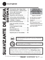
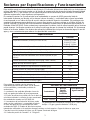
WATER SOFTENING
SYSTEM
Write the model and
serial numbers here:
Model # ______________
Serial # ______________
To find these numbers,
lift the cover and look on
the rim below the control
panel.
Model GXSF30V
Systems tested and certified by NSF International
against NSF/ANSI Standard 44 and certified to
NSF/ANSI/CAN 372.
Systems Tested and Certified by the Water Quality
Association against CSA B483.1.
If you have any questions or concerns when installing or maintaining
your water softener, call our toll free number at 800-952-5039 (US)
or 866-777-7627 (Canada), or visit GEAppliances.com. When you
call, please be prepared to provide the model and serial number
of your product. This information can be found on the rating decal
located on the rim under the salt cover.
ENGLISH/FRANÇAIS/
ESPAÑOL
CUS
R
Safety Information ............. 2
Specifications
and Performance Claims ........ 3
About the Softener ............ 4
Before you Start ............... 7
Installation Requirements ....... 8
Installation Instructions .........11
Programming the Softener ......16
Care and Cleaning .............21
Routine Maintenance .......... 22
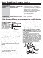
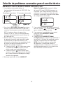
Before you call for Service .....24
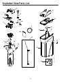
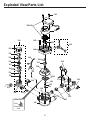
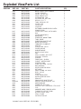
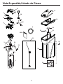
Exploded View/Parts List ......30
Limited Warranty (U.S.) ....... 33
Limited Warranty (Canada) ....34
Consumer Support ............ 36
7386392 49-6000298 Rev. 0 11-23
GE is a trademark of the General Electric Company. Manufactured under trademark license.
OWNER’S MANUAL
AND INSTALLATION
INSTRUCTIONS

2
IMPORTANT SAFETY INFORMATION.
READ ALL INSTRUCTIONS BEFORE USING
SAFETY PRECAUTIONS
WARNING
A copper or
galvanized cold water pipe may be used to
ground electrical outlets in the home. Failure to
maintain this ground path may result in an
electric shock hazard. If the cold water pipe is
used to ground electric outlets, please refer to
Installing the Ground Wire section before
cutting the pipe.
Check and comply with your state and local
codes. You must follow these guidelines.
Use care when handling the water softening
system. Do not turn upside down, drop, drag
or set on sharp protrusions.
Water softening systems using sodium
chloride (salt) for recharge add sodium to the
water.
Persons on sodium restricted diets should
consider the added sodium as part of their
overall intake. Potassium chloride can be
used as an alternative to sodium chloride in
your softener.
Use only lead-free solder and flux for all
sweat-solder connections, as required by
state and federal codes.
This water softening system must be properly
installed and located in accordance with the
installation instructions before it is used.
Keep the salt hole cover in place on the
softener unless servicing the unit or refilling
with salt.
WARNING
Do not use with
water that is microbiologically unsafe or of
unknown quality without adequate disinfection
before or after the system.
WARNING
Discard all unused
parts and packaging material after installation.
Small parts remaining after the installation
could be a choke hazard.
The water softening system works on 24 volt-
60 Hz
electrical power only. Be sure to use
the included external power supply.
External power supply must be plugged into
an indoor 120 volt, grounded outlet only.
Use clean water softening salts only, at least
99.5% pure. NUGGET, PELLET or coarse
SOLAR salts are recommended. Do not use
rock, block, granulated or ice cream making
salts. These types of salts may contain dirt
and sediments that might mush or cake,
creating maintenance issues for the water
softener.
Avoid installing in direct sunlight. Excessive
heat may cause distortion or other damage
to non-metallic parts.
If installing the water softener outdoors, do
not locate where it will be exposed to wet
weather, direct sunlight, extreme hot or cold
temperatures, or other forms of abuse.
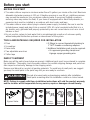
WARNING
For your safety, the information in this manual must be followed to
minimize the risk of electric shock, property damage or personal injury.
In the state of California: You must turn the
Salt Efficiency Feature setting to ON. This may
initiate more frequent recharges. However
it will operate at 4,000 grains per pound of
salt or higher. To turn on the Salt Efficiency
Feature, follow the instructions in the “SALT
EFFICIENCY” section of this manual.
In the Commonwealth of Massachusetts,
Plumbing Code 248 CMR shall be adhered
to. Consult with your licensed plumber.
READ AND SAVE THESE INSTRUCTIONS

3
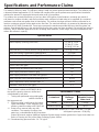
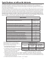
Specifications and Performance Claims
Specifications
Model GXSF30V
Rated Capacity* (Grains@ Salt Dose) 11,900 @ 2.5 lbs
25,300 @ 7.9 lbs.
30,100 @ 13.3 lbs.
Rated Efficiency** (Grains/Pound of Salt @ Minimum Salt Dose) 4,770 @ 2.5 lbs.
Water used during Regeneration (gallons/grains) 2.8 /1000
Total Water Used per Regeneration @ Maximum Salt Dose 35.5 gallons
Amount of High Capacity Ion Exchange Resin (lb/cu.ft.) 43/0.83
Resin Tank Nominal Size (in., dia. x height) 9 x 35
Service Flow Rate (gpm) 7.5
Pressure Drop at Rated Service Flow (psig) 13.4
Water Supply Maximum Hardness (gpg) 95
Water Supply Maximum Clear Water Iron (ppm)*** 8
Water Pressure Limits (minimum-maximum psi)**** 20-125
Water Temperature Limits (minimum-max. °F) 40-120
Maximum Flow Rate to Drain (gpm) 2.3
These systems conform to NSF/ANSI 44 for
the specific capacity claims as verified and
substantiated by test data.
* Testing was performed using pellet grade
sodium chloride as
the regenerant salt.
** Efficiency rating is valid only at the lowest
stated salt dosage. These softeners were
efficiency rated according to NSF/ANSI 44.
*** Extent of iron removal may vary with
conditions. The capacity to reduce clear
water iron is substantiated by WQA test data.
State of Wisconsin requires additional treatment if water supply contains greater than 5 ppm clear water iron.
Refer to Cleaning Iron Out of the Water Softening System section.
**** Canada working pressure limits: 1.4–7.0 kg/cm2.
This model is efficiency rated. The efficiency rating is valid only at the minimum stated salt dose. The softener has
a demand initiated regeneration (D.I.R) feature that complies with specific performance specifications intended to
minimize the amount of regenerant brine and water used in its operation.
The softener has a rated salt efficiency of not less than 4,000 grains of total hardness exchange per pound of
salt (based on sodium chloride), and shall not deliver more salt than its listed rating or be operated at a sustained
maximum service flow rate greater than its listed rating. This softener has been proven to deliver soft water for at
least ten continuous minutes at the rated service flow rate. The rated salt efficiency is measured by laboratory test
described in NSF/ANSI Standard 44. These tests represent the maximum possible efficiency that the system can
achieve. Operational efficiency is the actual efficiency after the system has been installed. It is typically less than the
efficiency, due to individual application factors including water hardness, water usage, and other contaminants that
reduce the softener’s capacity.
Performance Claims
Contaminant Influent
Challenge
Level
Maximum
Allowable Product
Water Level
Barium 10 ±10% mg/L 2.0 mg/L
Radium 226/228 25 pCi/L 5pCi/L
Test parameters include: pH = 7.5±0.5, flow rate = 7.5 gpm
and dynamic pressure = 35±5 psig

4
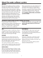
SERVICE
When the water softening system is providing
soft water, it is called “Service.” During service,
hard water flows from the house main water
pipe into the water softening system. Inside the
water softening system resin tank is a bed made
up of thousands of tiny, plastic resin beads. As
hard water passes through the bed, each bead
attracts and holds the hard minerals. This is
called ion-exchanging. It is much like a magnet
attracting and holding metals. Water without
hard minerals (soft water) flows from the water
softening system and to the house pipes.
After a period of time, the resin beads become
coated with hard minerals and they have to
be cleaned. This cleaning is called recharge.
Recharge is started at 2:00 AM (factory setting)
by the water softening system control, and
consists of five stages or cycles. These are
FILL, BRINING, BRINE RINSE, BACKWASH
and FAST RINSE.
AUTOMATIC HARD WATER BYPASS DURING RECHARGE
During recharge the water softener is
automatically put in bypass mode allowing hard
water to be available to the home. Once the
softener is recharged water is directed back
through the softener to be conditioned.
However, you should avoid using HOT water
because the water heater will fill with the
hard water.
FILL
Salt dissolved in water is called brine. Brine is
needed to clean the hard minerals from resin
beads. To make the brine, water flows into the
salt storage area during the fill stage.
BRINING
During brining, brine travels from the salt
storage area into the resin tank. Brine is the
cleaning agent needed to remove hard minerals
from the resin beads. The hard minerals and
brine are discharged to the drain.
The nozzle and venturi create a suction to
move the brine, maintaining a very slow rate to
get the best resin cleaning with the least salt.
BRINE RINSE
After a pre-measured amount of brine is used,
the brine valve closes. Water continues to flow
in the same path as during brining, except for
the discontinued brine flow. Hard minerals and
brine flush from the resin tank to the drain.
BACKWASH
During backwash, water travels up through
the resin tank at a fast flow rate, flushing
accumulated iron, dirt and sediments from the
resin bed and to the drain.
FAST RINSE
Backwash is followed by a fast flow of water
down through the resin tank. The fast flow
flushes brine from the bottom of the tank, and
packs the resin bed.
After fast rinse, the water softening system
returns to soft water service.
About the water softener system

5
FEATURE: OPTIONAL RECHARGE CONTROLS
Sometimes, a manually started recharge may
be desired or needed. Two examples:
You have used more water than usual
(house guests, extra washing, etc.) and you
may run out of soft water before the next
recharge.
The system ran out of salt.
Use one of the following features to start a
recharge immediately, or at the next preset
recharge start time.
RECHARGE TONIGHT
Touch (do not hold) the RECHARGE button.
RECHARGE TONIGHT flashes in the control
display area. A recharge will occur at the next
preset recharge start time. If you decide to
cancel this recharge, touch the same button
once more.
RECHARGE NOW
Press and hold the RECHARGE button until
RECHARGE NOW starts to flash in the control
display area. The water softening system
begins an immediate recharge and, when over
in about two hours, you will have a new supply
of soft water. Once started, you cannot cancel
this recharge.
FEATURE: MEMORY
If electrical power to the water softening system
is interrupted, the control display is blank, and
the blue indicator light is off, but the control
keeps correct time for 24 hours. When power
is restored, you have to reset the present time
only if the display and blue indicator light are
flashing. All other settings are maintained and
never require resetting unless a change is
desired.
If the time is flashing after a long power outage,
the water softening system continues to work
as it should to provide you with soft water.
However, recharge may occur at the wrong
time of day until you reset the control to the
correct time of day.
FEATURE/SERVICE: AUTOMATIC ELECTRONIC DIAGNOSIS
The control computer has a self-diagnostic
function for the electrical system (except
input power and water meter). The computer
monitors the electronic components and circuits
for correct operation. If a malfunction occurs, an
error code appears in the control display.
NORMAL OPERATION, CONTROL DISPLAYS
During normal operation, the present time of
day and AM or PM and DAYS TO EMPTY
show in the control display area.
The system will automatically recharge at the
preset recharge time as needed.
About the water softener system

6
WATER CONDITION INFORMATION
IRON
Iron in water can cause stains on clothing
and plumbing fixtures. It can negatively affect
the taste of food,drinking water, and other
beverages. Iron in water is measured in parts
per million (ppm). The total* ppm of iron, and
type or types*, is determined by chemical
analysis. Four different types of iron in water
are:
Ferrous (clear water) iron
Ferric (red water) iron
Bacterial and organically bound iron
Colloidal and inorganically bound iron
(ferrous or ferric)
Ferrous (clear water) iron is soluble and
dissolves in water. This water softener will
reduce moderate amounts of this type of iron
(see specifications).**Ferrous (clear water)
iron is usually detected by taking a sample of
water in a clear bottle or glass. Immediately
after taking, the sample is clear. As the water
sample stands, it gradually clouds and turns
slightly yellow or brown as air oxidizes the iron.
This usually occurs in 15 to 30 minutes.
When using the softener to reduce Ferrous
(clear water) iron, add 5 grains to the hardness
setting fore very 1 ppm of Ferrous (clear
water) iron. See “Set Water Hardness Number”
section.
Ferric (red water), and bacterial and organically
bound irons are insoluble. This water softener
will not remove ferric or bacterial iron. This
iron is visible immediately when drawn from a
faucet because it has oxidized before reaching
the home. It appears as small cloudy yellow,
orange, or reddish suspended particles. After
the water stands for a period of time,the
particles settle to the bottom of the container.
Generally these irons are removed from water
by filtration. Chlorination is also recommended
for bacterial iron.
Colloidal and inorganically bound iron is of
ferric or ferrous form that will not filter or
exchange out of water. This water softener will
not remove colloidal iron. In some instances,
treatment may improve colloidal iron water.
Colloidal iron water usually has a yellow
appearance when drawn. After standing for
several hours, the color persists and the iron
does not settle,but remains suspended in the
water.
SEDIMENT
Sediment is fine, foreign material particles
suspended in water. This water softener will
not remove sediment. This material is most
often clay or silt. Extreme amounts of sediment
may give the water a cloudy appearance. A
sediment filter installed upstream of the water
softener normally corrects this situation.
* Water may contain one or more of the four
types of iron and any combination of these.
Total iron is the sum of the contents.
** Capacity to reduce clear water iron is
substantiated by WQA test data.
CHLORINE
S
oftener resins may degrade in the presence
of chlorine above 2 ppm. If you have chlorine
in excess of this amount, you may experience
reduced life of the resin. In these conditions,
you may wish to consider purchasing a GE
Appliances point-of-entry household filtration
system with a chlorine reducing filter.
About the water softener system

7
BEFORE YOU START
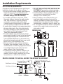
The water softener requires a minimum water flow of 3 gallons per minute at the inlet. Maximum
allowable inlet water pressure is 125 psi. If daytime pressure is over 80 psi, nighttime pressure
may exceed the maximum. Use a pressure reducing valve if necessary (Adding a pressure
reducing valve may reduce the flow). If your home is equipped with a back flow preventer, an
expansion tank must be installed in accordance with local codes and laws.
The water softener uses a direct plug-in external power supply (included). Be sure to use the
included power supply and plug it into a nominal 120V, 60 cycle household outlet that is in a
dry location only, grounded and properly protected by an over current device such as a circuit
breaker or fuse.
Do not use this system to treat water that is microbiologically unsafe or of unknown quality
without adequate disinfection upstream or downstream of the system.
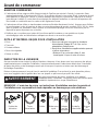
INSPECT SHIPMENT
Make sure all the parts shown below are present. Additional parts must be purchased to complete
the installation. Thoroughly check the water softener for possible shipping damage and parts loss.
Also inspect and note any damage to the shipping carton.
Remove and discard (or recycle) all packing materials. To avoid loss of small parts, we suggest
you keep the small parts in the parts bag until you are ready to use them.
Bypass Valve Drain Hose Clips Hose
Clamps Overflow
Adapter Grommet
WARNING
Discard all unused parts and packaging material after installation.
Small parts remaining after the installation could be a choke hazard.
TOOLS AND MATERIALS REQUIRED FOR INSTALLATION
Pliers
Screwdriver
Razor knife
Two adjustable wrenches
Teflon tape
2 fittings to connect household plumbing to
1” NPT threads on softening adaptors.
Additional installation parts may be required:
• UL-approved grounding clamps and
6-gauge copper grounding wire.
NOTE: Failure to comply with these installation instructions will void the product warranty,
and the installer will be responsible for any service, repair or damages caused thereby.
Silicone
Grease
Before you start

8
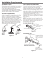
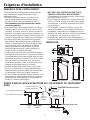
14-7/16"
TOP VIEW
SIDE VIEW FRONT VIEW
43-1/4"
22-7/16"
3-3/8"
IN
OUT
37"
IN - OUT
LOCATION REQUIREMENTS
Consider all of the following when selecting an
installation location for the water softener.
Do not locate the water softener where freezing
temperatures occur. Do not attempt to treat
water over 120ºF. Freezing temperatures or
hot water damage voids the warranty.
To condition all water in the home, install
the water softener close to the water supply
inlet, and upstream of all other plumbing
connections, except outside water pipes.
Outside faucets should remain on hard water
to avoid wasting conditioned water and salt.
A nearby drain is needed to carry away regeneration
discharge (drain) water. Use a floor drain,laundry
tub, sump, standpipe, or other options(check your
local codes). See “Air Gap Requirements” and
“Valve Drain Requirements”sections.
The water softener uses a direct plug-in external
power supply (included). Be sure to use the included
power supply and plug it into a nominal 120V, 60
cycle household outlet that is in a dry location only,
grounded and properly protected by an over current
device such as a circuit breaker or fuse.
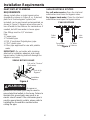
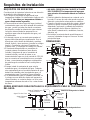
Always install the water softener between
the water inlet and water heater. Any other
installed water conditioning equipment should
be installed between the water inlet and
water softener (See Figure below).
If installing the water softener outdoors, do
not locate where it will be exposed to wet
weather, direct sunlight, extreme hot or cold
temperatures, or other forms of abuse.
DO NOT RUN HOT WATER THROUGH THE
SOFTENER. Temperature of water passing
through the softener must be less than 120° F.
Avoid installing in direct sunlight. Excessive
sun heat may cause distortion or other
damage to non-metallic parts.
When installing in an outside location you
must take steps necessary to assure the
softener, installation plumbing and wiring, are
protected from the elements, direct sunlight,
contamination, vandalism, insects, vermin, etc.
Do not install the softener where it would block
access to the water heater or access to the
main water shutoff.
DIMENSIONS
PROPER ORDER TO INSTALL WATER TREATMENT EQUIPMENT
Well
Pump
Well Water Supply
City Water Supply
OR
Pressure
Tank
Optional
Sediment
Filter
Water
Heater Water
Softener
Hot Water to House
Cold Water to House
Untreated Water to
Outside Faucets Shut off
valve
Installation Requirements

9
PLUMBING CODES
All plumbing must be completed in accordance
with national, state and local plumbing codes.
In the state of Massachusetts: The
Commonwealth of Massachusetts plumbing
code 248-CMR shall be adhered to. A licensed
plumber shall be used for this installation.
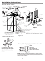
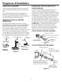
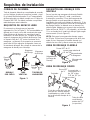
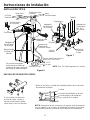
AIR GAP REQUIREMENTS
A drain is needed for regeneration water (See
Figure 1). A floor drain, close to the water
softener, is preferred. A laundry tub, standpipe,
etc. are other drain options. Secure valve
drain hose in place. Leave an air gap of 1-1/2”
between the end of the hose and the drain. This
gap is needed to prevent back flow of sewer
water into the water softener. Do not put the
end of the drain hose into the drain.
VALVE DRAIN REQUIREMENTS
Using the flexible drain hose (included) (See
Figure 2), measure and cut to the length
needed. Flexible drain hose is not allowed in all
localities (check your plumbing codes). If local
codes do not allow use of a flexible drain hose,
a rigid valve drain run must be used. Purchase
a compression fitting (1/4 NPT x 1/2 in.
minimum tube) and 1/2” tubing from your local
hardware store. Plumb a rigid drain as needed
(See Figure 3).
NOTE: Avoid drain hose runs longer than 30
feet. Avoid elevating the hose more than 8 feet
above the floor. Make the valve drain line as
short and direct as possible.
FLEXIBLE DRAIN LINE
RIGID DRAIN LINE
FlOOR
DRAIN STANDPIPE LAUNDRY
TUB
1-1/2”
air gap
1-1/2”
air gap
1-1/2”
air gap
Drain
Hose Drain
Hose
Drain
Hose
Figure 1 Clip
1/4Ǝ NPT thread
ƎRXWVLGH
diameter copper
tube (not provided)
Compression fitting
137[Ǝ2'
tube (not provided)
Cut barbs from valve drain
elbow (pull clip and remove
drain valve elbow from valve)
Barbs
Figure 3
Barbs for 3/8
Ǝ
I.D. tubing
Hose clamp
Drain hose
1/4” NPT Thread
Figure 2
Drain hose adapter
Installation Requirements

10
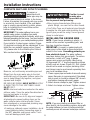
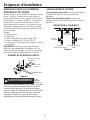
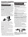
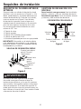
INLET/OUTLET PLUMBING
REQUIREMENTS
Always install either a single bypass valve
(provided),as shown in Figure 4, or, if desired,
parts for a 3 valve bypass system (not
included) can be purchased and assembled, as
shown in Figure 5. Bypass valves allow you to
turn off water to the softener for maintenance if
needed, but still have water in house pipes.
Pipe fittings must be 1/2” minimum.
Use:
Copper pipe
Threaded pipe
PEX (Crosslinked Polyethylene) pipe
CPVC plastic pipe
Other pipe approved for use with potable
water
IMPORTANT: Do not solder with plumbing
attached to installation adaptors and single
bypass valve. Soldering heat will damage the
adaptors and valve.
WARNING
A copper or
galvanized cold water pipe may be used to
ground electrical outlets in the home. Failure to
maintain this ground path may result in an
electric shock hazard. If the cold water pipe is
used to ground electric outlets, please refer to
Installing the Ground Wire section before
cutting the pipe.
3-VALVE BYPASS SYSTEM
For soft water service: Open the inlet and
outlet valves and close the bypass valve.
For bypass hard water: Close the inlet and
outlet valves and open the bypass valve.
3 VALVE BYPASS
Bypass
Valve
Outlet
Valve Inlet
Valve
From Water
Softener To Water
Softener
Figure 5
SINGLE BYPASS VALVE
Pull out for “Service”
(Soft water)
Push in for
“Bypass”
Figure 4
Installation
adaptors
Installation Requirements

11
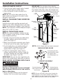
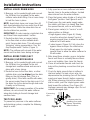
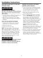
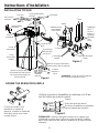
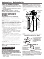
TYPICAL INSTALLATION
• Remove plastic shipping plug and wire from valve outlet.
Figure 8
Turbine
Valve outlet
Turbine shaft and support
Plastic shipping plug
NOTE: Be sure the turbine and support are firmly in place
in the valve outlet. Blow into the valve port and observe the
turbine for free rotation.
Clips
Inlet
Outlet
Lubricated
O-ring Single
Bypass Valve
1” NPTF
Sweat
Adaptor
(not
included)
Pipe
1-1/2”
air gap
Floor Drain
Secure Valve Drain Hose in
place over Floor Drain
Salt Storage
Tank Overflow
Hose*
Overflow Drain
Elbow
Conditioned
Water
To Outside
Faucets
Plug-in
Power
Supply
To
Controller
Valve Drain
Elbow
Valve Drain
Hose*
*Do not connect the
water softener valve drain
tubing to the salt storage
tank overflow hose. NOTE: See “Air Gap Requirements” section.
Figure 6
Figure 7
Drain
Hose
Adapter
Hard Water Main Water Pipe
SINGLE BYPASS VALVE
If connecting to floor level
plumbing, install the bypass
valve turned downward, as
shown.
Installation Instructions

12
TURN OFF WATER SUPPLY
1. Close the main water supply valve, located
near the well pump or water meter.
2. Open all faucets to drain all water from
house pipes.
NOTE: Be sure not to drain water from the
water heater, as damage to the water heater
elements could result.
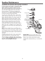
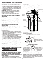
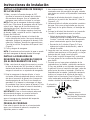
INSTALL THE BRINE TANK OVERFlOW
ADAPTER
Install the brine tank overflow grommet and
adapter in the 13/16” diameter hole in the back
of the salt storage tank sidewall, (see Figure 9).
NOTE: The brine tank overflow adapter accepts
either 1/2” or 3/8” I.D. hose.
INSTALL THE BYPASS VALVE
NOTE: For easier installation, remove the top
cover. Release 2 clips at rear of cover. Rotate
cover forward and lift up.
1. Visually check and remove any debris from
the water softener valve inlet and outlet
ports, (see Figure 7).
2. Make sure the turbine assembly spins freely
in the”out” port of the valve, (see Figure 8).
3. If not already done, put a light coating of
silicone grease (provided) on the single
bypass valve o-rings, (see Figure 7).
4. Push the single bypass valve into the
softener valve as far as it will go. Snap the
two large holding clips into place, from the
top down, (see Figure 7 and 10).
IMPORTANT: Be sure the clips snap firmly into
place so the single bypass valve will not pull out.
MOVE WATER SOFTENER INTO PLACE
WARNING
Excessive Weight Hazard
Use two or more people to move and install
water Softener Failure to do so can result in
back or other injury.
1. Move the water softener into the desired
location. Set it on a solid, level surface.
IMPORTANT: Do not place shims directly
under the salt storage tank to level the softener.
The weight of the tank, when full of water and
salt, may cause the tank to fracture at the shim.
SINGLE BYPASS VALVE
If connecting to floor
level plumbing, install
the bypass valve
turned downward, as
shown.
CORRECT ASSEMBLY
Outside diameter
of clip channel on
single bypass valve
Clip
Outside diameter of
water softener valve
inlet & outlet
NOTE: Be sure all 3 tabs of the clip go through the
matching holes on the water softener valve inlet or
outlet, and fully into the channel on the single bypass
valve. Make sure that the tabs are fully seated.
Figure 10
NOTE: Unit is shown with top cover removed.
Installation Instructions
Salt
Cover
Brinewell
Cover
Salt
Storage
Tank
Brinewell
Brine
Tubing
Brine Tank
Overflow
Elbow
Grommet
Hole
Nut - Ferrule
Nozzle Venturi
Assembly
Figure 9
Brine
Valve

13
COMPLETE INLET AND OUTLET PLUMBING
WARNING
A copper or
galvanized cold
water pipe may be
used to ground electrical outlets in the home.
Failure to maintain this ground path may result
in an electric shock hazard. If the cold water
pipe is used to ground electric outlets, please
refer to Installing the Ground Wire section
before cutting the pipe.
IMPORTANT: This water softener has a non-
metallic valve system. Installing it on metal
plumbing will break electrical continuity, which may
interrupt grounding for the home. You must restore
electrical continuity in your metal plumbing system.
If you install a 3-valve bypass system (Figure
5), electrical continuity will be maintained. If you
install the non-metallic bypass valve (Figure
11), please refer to the Installing the Ground
Wire section before cutting the pipe.
Measure, cut, and loosely assemble pipe and
fittings from the main water pipe to the inlet
and outlet ports of the water softener valve. Be
sure to keep fittings fully together, and pipes
squared and straight.
BE SURE INCOMING HARD WATER SUPPLY
IS DIRECTED TO THE SOFTENER VALVE
INLET PORT.
NOTE: Inlet and outlet are marked on the water
softener valve. Trace the water flow direction to
be sure hard water is to inlet.
IMPORTANT: Be sure to fit, align and support
all plumbing to prevent putting stress on the
water softener valve inlet and outlet. Stress
from misaligned or unsupported plumbing may
cause damage to the valve.
• If making a soldered copper installation, do all
sweat soldering before connecting pipes to
the NPT adapters and bypass valve. Torch
heat will damage plastic parts.
WARNING
If solder is used
to make pipe
connection use only lead free solder and
flux to prevent lead poisoning.
• When turning threaded pipe fittings onto
plastic fittings, use care not to cross-thread.
• Use Teflon Tape on all external pipe threads.
Complete the inlet and outlet plumbing for the
type of pipe you will be using. Secure ground
clamp to metal pipes.
INSTALLING THE GROUND WIRE
NOTE: If your house plumbing is plastic, it
would not be used as a grounding path, and
this step should be skipped.
IMPORTANT: A copper or galvanized cold
water pipe is often used to ground electrical
outlets in the home. Grounding protects you
from electrical shock. The water softener
may have broken this ground path. To restore
connection, install a 12”-long, 6-gauge
copper wire across and tightly clamp using
UL-approved 1/2”–1” bronze grounding clamps
at both ends as shown (Figure 12). Zinc clamps
should not be used on copper plumbing. Wire
and clamps may be purchased separately from
your local hardware store.
1. Clean copper pipe and ends of wire with emery
paper. Bare wire is recommended. If insulated
wire is used, is should be stripped 3/4” at each
end before cleaning with emery paper.
2.
Attach bronze clamps to pipe. Tighten screws.
3. Attach to clamps as shown. Tighten screws.
NOTE: If you are installing a sediment filter or
other item(s) into the plumbing system, along with
the water softener, be sure to restore electrical
continuity across all removed metal pipe sections.
Figure 11
Figure 12
Ground Wire
Clamp (2)
Installation Instructions

14
INSTALL VALVE DRAIN HOSE
1. Measure, cut to needed length and connect
the 3/8”drain line (provided) to the water
softener valve drain fitting. Use a hose clamp
to hold the hose in place.
NOTE: Avoid drain hose runs longer than 30
feet. Avoid elevating the hose more than 8 feet
above the floor. Make the valve drain line as
short and direct as possible.
IMPORTANT: If codes require a rigid drain line
see“Valve Drain requirements” section.
2. Route the drain hose or copper tubing
to the floor drain or other suitable drain
point. Secure drain hose. This will prevent
“whipping’’ during regenerations. See “Air
Gap Requirements” section (Figure 1).
NOTE: The softener will not work if the water
cannot exit the drain hose during recharge.
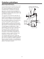
INSTALL BRINE TANK (SALT
STORAGE) OVERFlOW HOSE
1. Measure, cut to needed length and connect
the 3/8”drain line (provided) to the salt
storage tank overflow elbow and secure in
place with a hose clamp.
2. Route the hose to the floor drain, or other
suitable drain point no higher than the drain
fitting on the salt storage tank (This is a
gravity drain). If the tank overfills with water,
the excess water flows to the drain point. Cut
the drain line to the desired length and route
it neatly out of the way.
IMPORTANT: For proper operation of the water
softener, do not connect the water softener
valve drain tubing to the salt storage tank
overflow hose.
TEST FOR LEAKS
To prevent air pressure in the water softener
and plumbing system, complete the following
steps in order:
1. Fully open two or more softened cold water
faucets close to the water softener, located
down stream from the water softener.
2. Place the bypass valve (single or 3 valve) into
the”bypass” position. See Figures 4 and 5.
3. Slowly open the main water supply valve.
Run water until there is a steady flow from
the opened faucets, with no air bubbles.
4. Place bypass valve(s) in “service” or soft
water position as follows:
• Single bypass valve (Figure 4): Slowly
move the valve stem toward “service,”
pausing several times to allow the water
softener to fill with water.
• 3 valve bypass (Figure 5): Fully close the
bypass valve and open the outlet valve.
Slowly open the inlet valve, pausing
several times to allow the water softener to
fill with water.
5. After about three minutes, open a hot water
faucet until there is a steady flow and there
are no air bubbles, then close this faucet.
6. Close all cold water faucets and check for
leaks at the plumbing connections that you
made.
7. Check for leaks around clips at softener’s
inlet and outlet. If a leak occurs at a clip,
depressurize the plumbing (turn off the water
supply and open faucets) before removing
clip. When removing clips at the softener’s
inlet or outlet, push the single bypass valve
body toward the softener (See Figure 13).
Improper removal may damage clips. Do not
reinstall damaged clips.
....depressurize the
plumbing, then push
Bypass Valve body
toward softener
If removing
clips.....
Figure 13
Installation Instructions

15
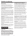
ADD WATER AND SALT TO THE SALT
STORAGE TANK
WARNING
EXCESSIVE WEIGHT HAZARD:
Use two or more people to move and lift salt
bags. Failure to do so can result in back or
other injuries.
1. Using a container, add about three gallons of
clean water into the salt storage tank.
2. Add salt to the storage tank. Use nugget,
pellet or coarse solar salts with less than 1%
impurities.
PLUG IN THE WATER SOFTENER
1. Plug the water softener into an electrical
outlet that is not controlled by a switch.
2. Replace the top cover.
3. Replace the salt hole cover.
NOTE: The water heater is filled with hard
water and,as hot water is used, it will refill
with conditioned water. In a few days, the hot
water will be fully conditioned. To have fully
conditioned hot water immediately, wait until
the initial recharge is over. Then, drain the
water heater(following instructions for water
heater) until water runs cold.
WARNING
Discard all unused
parts and packaging material after
installation. Small parts remaining after the
installation could be a choke hazard.
SANITIZE THE WATER SOFTENER /
SANITIZE AFTER SERVICE
1. Open salt hole cover, remove the brinewell
cover and pour about 3 oz. (6 tablespoons)
of household bleach into the softener
brinewell. Replace the brinewell cover.
2. Make sure the bypass valve(s) is in the
“service”(open) position.
3. Start a recharge (regeneration) as follows:
Press the RECHARGE button and hold for
three seconds, until “RECHARGE NOW”
begins to flash in the display, starting a
recharge. This recharge draws the sanitizing
bleach or brine into and through the water
softener. Any air remaining in the water
softener is purged to the drain. During this
time periodically check for leaks.
NOTE: As with all other water system
applications, leaks may occur. Leaks may not
be immediately apparent. Recheck 24 hours
after first recharge cycle is complete.
4. After the recharge has completed, fully open
a cold water faucet, downstream from the
softener, and allow 50 gallons of water to
pass through the system. This should take at
least 20 minutes. Close the faucet.
Installation Instructions

16
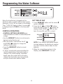
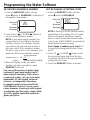
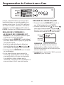
e
When the transformer is plugged into the
electrical outlet, a model code and test number
(example: J3.4 & F30) are shown in the display.
Then, “12:00 PM” begins to flash. An arrow
is displayed next to CLOCK on the face plate
decal.
CONTROL OPERATION:
• CONTROL SETTINGS REQUIRED upon
initial installation and after an extended power
outage.
• Use the MODE/SET button to scroll arrow to
desired control function set.
• After the mode is selected use the UP
and DOWN buttons to change the
settings of the control.
• Press the MODE/SET button to accept
changes.
• A “beep” sounds while pressing buttons for
control programming. One beep signals a
change in the control display. Repeated
beeps mean the control will not accept a
change from the button you have pressed,
and you should select another button.
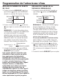
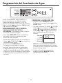
SET TIME OF DAY
1. Press MODE/SET button until the arrow
points to CLOCK.
2. Press the UP or DOWN buttons
to set the present time. UP moves the
display ahead; DOWN sets the time
back. Be sure AM and PM is correct.
NOTE: Press buttons and quickly release
to slowly advance the display one number
at a time. Hold the buttons down for fast
advance.
3. When the correct time is shown in the
display, press MODE/SET to accept.
Salt Level
Clock
Hardness
Recharge
PM
Programming the Water Softener

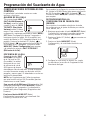
17
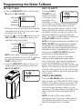
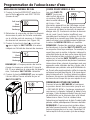
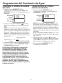
SET WATER HARDNESS NUMBER
1. Press the MODE/SET button until the
arrow points to HARDNESS. A flashing 25
will appear in the display.
2. Press the UP or DOWN buttons to
set your water hardness number.
NOTE: If your water supply contains iron,
compensate for it by adding to the water
hardness number. For example, assume
your water is 20 gpg hard and contains 2
ppm iron. Add 5 to the hardness number
for each 1 ppm or iron. In this example, you
would use 30 for your hardness number.
3. When the display shows your water
hardness (in grains per gallon), press
MODE/SET to accept.
You can get the grains per gallon (gpg)
hardness of your water supply from a
water analysis laboratory. If you are on
a municipal supply, call your local water
department. Or call Legend Technical
Services, an independent laboratory,
to request a water hardness test kit at
1.800.949.8220, Option 4. If your report
shows hardness in parts per million (ppm)
or milligrams per liter (mg/l), simply divide
by 17.1 to get the equivalent number of
grains per gallon.
SET RECHARGE (STARTING) TIME
1. Press the MODE/SET button until the
arrow points to RECHARGE.
NOTE: A flashing 2:00 AM (factory default)
should show in the display. This is a good
time for recharge to start (takes about 2
hours) in most households because water
is not in use. HARD WATER is bypassed to
house faucets during recharge.
If no change is needed, go to step 3. To
Change the recharge starting time, follow
step 2.
2. Press UP or DOWN button to set
the desired recharge start time. Be sure
to observe the AM or PM as you did when
setting the time of day.
3. Press the MODE/SET button to accept.
Programming the Water Softener
20 gpg hardness
2 ppm iron x 5 = 10 +10
(times) 30 HARDNESS NUMBER
Salt Level
Clock
Hardness
Recharge
Salt Level
Clock
Hardness
Recharge
AM

18
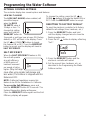
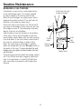
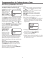
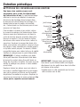
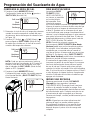
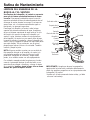
SET SALT LEVEL
1. Press the MODE/SET button until the arrow
points to SALT LEVEL.
2. Determine level of salt in brine tank using the
numbered scale on side of brine well, inside
brine tank (see Figure 14).
3. Press UP or DOWN button to set the
SALT LEVEL to correspond to level on the
numbered scale in brine tank.
NOTE: Each press of a button changes the
level by increments of 0.5 up to 8.0. Lowering
the salt level below zero turns the SALT
LEVEL indicator OFF.
4. Press the MODE/SET button to accept. The
display shows the present time of day and
DAYS TO EMPTY.
DAYS TO EMPTY
The words DAYS
TO EMPTY and a
number are shown
in the lower half of
the display. This
information is shown
in the normal run display. This is to inform the
user of the number of days before the salt
level in the brine tank reaches Level 0. There
will be salt left in the salt tank, but it may not
be sufficient to fully recharge the system. Salt
should be added at this time to avoid hard
water. The value is updated daily and whenever
the SALT LEVEL value is changed.
NOTE: For the first several weeks of operation, the
DAYS TO EMPTY may provide erratic operation.
For example, the blue indicator light may flash,
showing that more salt is required when the actual
salt level in the tank is well above the Level 0. In
some cases, the DAYS TO EMPTY may even
increase over a several week period.
It takes a couple of months for the water
softener to learn your water usage pattern.
Once it does this, it will accurately determine
actual salt usage pattern. During this first
period, check salt level when blue indicator light
flashes. If the salt level in the tank is at Level 1
or above, allow system to run. Be sure to reset
your salt level indicator each time you add salt
to the system.
START A RECHARGE
Press the RECHARGE button and hold for
three seconds, until “RECHARGE NOW” begins
to flash in the display, starting a recharge. This
recharge draws the sanitizing bleach or brine
into and through the water softener. Any air
remaining in the water softener is purged to the
drain. During this time periodically check for
leaks.
NOTE: As with all other water system
applications, leaks may occur. Leaks may not
be immediately apparent. Recheck 24 hours
after first recharge cycle is complete.
Salt Level
Clock
Hardness
Recharge
Salt Level
Clock
Hardness
Recharge
AM
Days to Empty
PM
Days to Empty
8
7
6
5
4
3
2
1
Figure 14
Programming the Water Softener

19
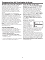
OPTIONAL CONTROL SETTINGS
The controller display has several options and features.
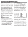
LOW SALT ALARM
The LOW SALT ALARM, when enabled, will
sound the beeper
when the DAYS
TO EMPTY value is
15 days or less. To
change this setting,
press and hold the
MODE/SET button for
3 seconds or until you hear a beep. ON (factory
default) or OFF will flash in the display. Press
the UP or DOWN buttons to toggle
this feature ON or OFF. Press the MODE/SET
button to accept, and the display will move to
SALT EFFICIENCY.
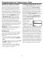
SALT EFFICIENCY
When the SALT EFFICIENCY feature is ON,
the unit will operate
at a salt efficiency
of 4000 grains of
hardness removed
per pound of salt or
higher. (May recharge
more often using smaller salt dosage and
less water.) The softener is shipped with this
feature set OFF.
NOTE: California Regulations require this
feature to be ON for installations in California.
To access the Salt Efficiency, press and
hold the MODE/SET button for 3 seconds. The
System Diagnostics display will appear.
Press the MODE/SET button again and the Salt
Efficiency display will appear.
To change the setting, press the UP or
DOWN buttons to toggle the feature ON or
OFF. Press the MODE/SET button to accept.
RESETTING TO FACTORY DEFAULT
To reset the electronic controller to its factory
default for all settings (time, hardness, etc.):
1. Press the MODE/SET button and hold
until the display changes twice to show the
flashing mode code.
2. Press the UP button to display a flashing
“SoS”.
3. Press the MODE/SET button and the
electronic controller will restart.
4. Set the present time, hardness, etc, as
described in the Programming the Water
Softener section.
e
Programming the Water Softener

20
POWER OUTAGE MEMORY
If electrical power to the water softener is
lost, “memory’’ built into the timer circuitry will
keep all settings for up to 24 hours. While the
power is out, the display is blank and the water
softener will not regenerate. When electrical
power is restored, the following will occur:
Reset the present time only if the display is
flashing. The HARDNESS and RECHARGE
TIME never require resetting unless a change
is desired. Even if the clock is incorrect after
a long power outage, the softener operates
as it should to keep your water soft. However,
regenerations may occur at the wrong time of
day until you reset the clock to the correct time
of day.
NOTE: If the water softener was regenerating
when power was lost, it will now finish the
cycle.
BLUE INDICATOR LIGHT
Steady blue light indicates that the unit is
working correctly. The light flashes when the
unit needs attention from the user.
• Light will also flash when power to until has
been interrupted. Check the PRESENT TIME
setting.
• Light flashes and DAYS TO EMPTY flashes -
check salt level and add salt as required.
• Light flashes and Err is in the display -
electrical problem with system (see page 27).
LOW SALT SIGNAL
When the DAYS TO EMPTY drops to 15, the
blue indicator light and DAYS TO EMPTY in
the display will flash every second and the
alarm will beep every 30 seconds (from 8:00
AM to 8:00 PM), to notify the user that the unit
is running low on salt. As soon as any button
is pressed, the alarm will stop beeping. The
blue indicator light and DAYS TO EMPTY will
continue to flash. Once salt is added to the
brine tank and the SALT LEVEL is reset, the
DAYS TO EMPTY will be reset.
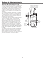
ERROR SIGNALS
If there is an error
code detected, the
blue indicator light
will flash 4 times
every second, the
display will flash Err
and the alarm will beep every 30 seconds (from
8:00 AM to 8:00 PM) to signal that the softener
requires service. The alarm can be turned off
by pressing any button, but the blue indicator
light and display will continue to flash.
Disconnect the transformer from the wall
outlet momentarily, and plug it back in. The
normal display will appear. The motor may run
for several minutes, as the unit resets. If the
problem is not corrected, the error code will
reappear in 8 minutes. See the Before you Call
for Service section to assist in troubleshooting
the water softener.
Call for Service
Programming the Water Softener
La page charge ...
La page charge ...
La page charge ...
La page charge ...
La page charge ...
La page charge ...
La page charge ...
La page charge ...
La page charge ...
La page charge ...
La page charge ...
La page charge ...
La page charge ...
La page charge ...
La page charge ...
La page charge ...
La page charge ...
La page charge ...
La page charge ...
La page charge ...
La page charge ...
La page charge ...
La page charge ...
La page charge ...
La page charge ...
La page charge ...
La page charge ...
La page charge ...
La page charge ...
La page charge ...
La page charge ...
La page charge ...
La page charge ...
La page charge ...
La page charge ...
La page charge ...
La page charge ...
La page charge ...
La page charge ...
La page charge ...
La page charge ...
La page charge ...
La page charge ...
La page charge ...
La page charge ...
La page charge ...
La page charge ...
La page charge ...
La page charge ...
La page charge ...
La page charge ...
La page charge ...
La page charge ...
La page charge ...
La page charge ...
La page charge ...
La page charge ...
La page charge ...
La page charge ...
La page charge ...
La page charge ...
La page charge ...
La page charge ...
La page charge ...
La page charge ...
La page charge ...
La page charge ...
La page charge ...
La page charge ...
La page charge ...
La page charge ...
La page charge ...
La page charge ...
La page charge ...
La page charge ...
La page charge ...
La page charge ...
La page charge ...
La page charge ...
La page charge ...
La page charge ...
La page charge ...
La page charge ...
La page charge ...
La page charge ...
La page charge ...
La page charge ...
La page charge ...
-
 1
1
-
 2
2
-
 3
3
-
 4
4
-
 5
5
-
 6
6
-
 7
7
-
 8
8
-
 9
9
-
 10
10
-
 11
11
-
 12
12
-
 13
13
-
 14
14
-
 15
15
-
 16
16
-
 17
17
-
 18
18
-
 19
19
-
 20
20
-
 21
21
-
 22
22
-
 23
23
-
 24
24
-
 25
25
-
 26
26
-
 27
27
-
 28
28
-
 29
29
-
 30
30
-
 31
31
-
 32
32
-
 33
33
-
 34
34
-
 35
35
-
 36
36
-
 37
37
-
 38
38
-
 39
39
-
 40
40
-
 41
41
-
 42
42
-
 43
43
-
 44
44
-
 45
45
-
 46
46
-
 47
47
-
 48
48
-
 49
49
-
 50
50
-
 51
51
-
 52
52
-
 53
53
-
 54
54
-
 55
55
-
 56
56
-
 57
57
-
 58
58
-
 59
59
-
 60
60
-
 61
61
-
 62
62
-
 63
63
-
 64
64
-
 65
65
-
 66
66
-
 67
67
-
 68
68
-
 69
69
-
 70
70
-
 71
71
-
 72
72
-
 73
73
-
 74
74
-
 75
75
-
 76
76
-
 77
77
-
 78
78
-
 79
79
-
 80
80
-
 81
81
-
 82
82
-
 83
83
-
 84
84
-
 85
85
-
 86
86
-
 87
87
-
 88
88
-
 89
89
-
 90
90
-
 91
91
-
 92
92
-
 93
93
-
 94
94
-
 95
95
-
 96
96
-
 97
97
-
 98
98
-
 99
99
-
 100
100
-
 101
101
-
 102
102
-
 103
103
-
 104
104
-
 105
105
-
 106
106
-
 107
107
-
 108
108


dans d''autres langues
- English: GE GXSF30V Owner's manual
- español: GE GXSF30V El manual del propietario
Documents connexes
Autres documents
-
Pentair OMNIFILTER OM26K Le manuel du propriétaire
-
OmniFilter OM34K/OM40K Le manuel du propriétaire
-
 Kinetico 4040s with Overdrive Le manuel du propriétaire
-
-
 Kenmore Elite 625385200 Guide d'installation
-
Castorama Integral Manuel utilisateur
-
vitapur VWS296GR Manuel utilisateur
-

