
do not throw away, requires professional recycling
Class II equipment
for indoor use only
VI energy efficiency marking (level VI)
DC voltage
Index of Icons
7
~AC voltage
Responsible Party: PAX Technology Inc.
Address: 8880 Freedom Crossing Trail, Building 400, 3rd Floor,
Suite 300, Jacksonville, Florida 32256
T: 1-877-859-0099
P/N: 200312000000378
PAX TECHNOLOGY LIMITED reserves
the right to change product specifications
without prior notification.
Quick Setup Guide
78 9 10
l'appareil ne doit pas produire de brouillage, et
1)
2) l'utilisateur de l'appareil doit accepter tout brouillage
radioélectrique subi, même si le brouillage est
susceptible d'en compromettre le fonctionnement.
This device and its antenna(s) must not be co-located or
operating in conjunction with any other antenna or
transmitter, except tested built-in radios.
Cet appareil et son antenne ne doivent pas être situés ou
fonctionner en conjonction avec une autre antenne ou un
autre émetteur, exception faites des radios intégrées qui
ont été testées.
The Country Code Selection feature is disabled for
products marketed in the US/Canada.
La fonction de sélection de l’indicatif du pays est
désactivée pour les produits commercialisés aux États-
Unis et au Canada.
Radiation Exposure Statement
This equipment complies with IC radiation exposure limits
set forth for an uncontrolled environment. This
equipment should be installed and operated with
minimum distance 20cm between the radiator & your
body.
avec un minimum de 20 cm de distance entre la source
de rayonnement et votre corps.
Manufacturer: PAX Computer Technology (Shenzhen) Co., Ltd.
Address: 4FL, Building #3, Software Park, 2nd Central Science-
Tech RD, High-Tech Industrial Park, Shenzhen, Guangdong, PRC
T: 0755-86169630 F: 0755-86169634
W: http://www.pax.com.cn
IM20
POS TERMINAL
Cet équipement est conforme aux limites d'exposition
aux rayonnements IC établies pour un environnement
non contrôlé. Cet équipement doit être installé et utilisé
Déclaration d'exposition aux radiations:
UL 121201
PRODUCTS MARKED "CLASS I, DIV 2, GP A, B, C, D" ARE
SUITABLE FOR USE IN CLASS I DIVISION 2 GROUPS A, B,
C, D, HAZARDOUS LOCATIONS AND NONHAZARDOUS
LOCATIONS ONLY.
1)
LES PRODUITS MARQUÉS "CLASS I, DIV 2, GP A, B, C, D"
NE CONVIENNENT QU'À UNE UTILISATION EN
ENVIRONNEMENTS DE CLASSE I DIVISION 2 GROUPES
A, B, C, D DANGEREUX ET NON DANGEREUX.
1)
WARNING - EXPLOSION HAZARD - DO NOT
DISCONNECT EQUIPMENT WHILE THE CIRCUIT IS LIVE
OR UNLESS THE AREA IS KNOWN TO BE FREE OF
IGNITABLE CONCENTRATIONS.
2)
AVERTISSEMENT - RISQUE D'EXPLOSION - NE PAS
DÉBRANCHER L’ÉQUIPEMENT LORSQUE LE CIRCUIT EST
SOUS TENSION OU SI LA ZONE EST EXEMPTE DE
MATÉRIEL INFLAMMABLE.
2)
THIS DEVICE IS INTENDED TO BE PANEL MOUNTED ON
THE FRONT OR THE SIDE OF TOOL SECURED
ENCLOSURES BY FOUR MOUNTING UNITS TO FIX THE
AUXILIARY FIXED PART WITH THE MOUNTING PANEL
AND ANOTHER FOUR MOUNTING UNITS ON THE REAR
SIDE OF THE DEVICETO FIX WITH THE AUXILIARY FIXED
PART. THE REAR SIDE OF THE MODULE MUST BE
PLACED
3)
PLACED INTO A TOOL SECURED ENCLOSURE IN THE
FINAL INSTALLATION. THE SUITABLE INSTALLATION
METHODS SHALL BE PROVIDED AS TECHNICAL
ASSISTANCE FOR END USER AND SHALL BE SUBJECT TO
INVESTIGATION BY THE LOCAL AUTHORITY HAVING
JURISDICTION AT THE TIME OF INSTALLATION.
TEMPERATURE CODE: T4A
4)
CODE DE TEMPÉRATURE: T4A
4)
AMBIENT TEMPERATURE RANGE: -20°C TO 70°C.
5)
PLAGE DE TEMPÉRATURES AMBIANTES: -20°C TO 70°C.
5)

12345 6
Please make sure the following items are included with
your IM20 POS terminal. If any items are missing,
contact your dealer.
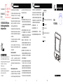
Figure 1: front view
1. LCD & Touchscreen
2. Smart Card & Magnetic Strip Card Reader
3. Status Indicator Light
4. Camera
5. Camera Indicator Light
Figure 2: back view
6. Type-B
7. RS232
8. MDB Port
1
3
2
4
5
6
7
8
Contents
Name Quantity
IM20 POS Terminal 1
USB Cable 1
M4 Nut 4
M3 Screw 4
Mounting Bracket 1
IM20 Quick Setup Guide 1
Product Description
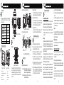
9
10
9.SAM Card Cover
10.Speaker
1) SAM Cards
Figure 4: SAM card mounts
SAM2
SAM3 SAM1
Remove the SAM card cover. Open the card mount and
insert the card into the slot with the contacts facing
downwards and the clipped corner of the card to the
upper left, then lock the mount and replace the SAM
card cover.
Figure 3: view from all sides
Installation
3) Recommended Device Installation
140
122
73
45
73
61
61
48
2) IM20 Clearance Holes and Dimensions
Figure 6: installation and mounting
Instructions
Figure 5: device dimensions (mm)
1) Switching the device on and off
Switch off:
Link the IM20 to a power source via
the USB or MDB terminal (make sure to
have the correct voltages and pinouts).
Switch on:
Disconnect the IM20 from the power
terminal it is connected to.
M4 Nuts
1
3
2
Mounting Bracket IM20 M3 Screws
2)
3) Magnetic Strip Card Interface
4)
Maintenance and Usage
5
Smart Card Interface
Insert the card fully into the card reader slot with the
contacts oriented upwards and towards the IM20.
Orient the card with the magnetic strip facing down
and to the right, then insert the card fully into the card
reader slot before quickly pulling out the card.
Contactless Interface
Orient the card or NFC device parallel to the LCD
screen and then place it directly above the screen.
1)
Replace any damaged cables immediately.
2)
Make sure the various cables connect to provide the
appropriate voltages at the proper pins.
3)
Do not insert unknown materials into any port on the
IM20, this may cause serious damage to the device.
4)
If the IM20 requires repair, contact a professional
technician instead of attempting them yourself.
5)
The IM20 is designed for outdoor use; however, it
should still be keep clear of possible contaminants.
6)
While the IM20 is designed to resist ingress of dust and
liquids, it is not designed to resist pressurized liquids
such as water hoses. Keep the back of the device away
from dust and liquids as much as possible.
Compliance Statements
this device may not cause harmful interference, and
this device must accept any interference received,
including interference that may cause undesired
operation.
1)
2)
Warning
FCC COMPLIANCE STATEMENT
This device complies with Part 15 of the FCC Rules.
Operation is subject to the following two conditions:
This equipment generates, uses and can radiate radio
frequency energy and, if not installed and used in
accordance with the instructions, may cause harmful
interference to radio communications.
However, there is no guarantee that interference will not
occur in a particular installation. If this equipment does
cause harmful interference to radio or television
reception, which can be determined by turning the
equipment off and on, the user is encouraged to try to
correct the interference by one of the following measures:
This equipment has been tested and found to comply with
the limits for a Class B digital device, pursuant to Part 15
of the FCC Rules. These limits are designed to provide
reasonable protection against harmful interference in a
residential installation.
•Increase the separation between the equipment and
receiver.
•Connect the equipment into an outlet on a circuit
different from that to which the receiver is connected.
•Consult the dealer or an experienced radio/TV
technician for help.
Caution
Any changes or modifications not expressly approved by
the manufacturer could void the user's authority to
operate this equipment.
Radiation Exposure
This device complies with FCC radiation exposure limits
for general environments.
•Reorient or relocate the receiving antenna.
This device complies with Industry Canada license-exempt
RSS standard(s). Operation is subject to the following
two conditions:
INDUSTRY CANADA STATEMENT
this device may not cause interference, and
1)
2) this device must accept any interference, including
interference that may cause undesired operation of
the device.
Le présent appareil est conforme aux CNR d'Industrie
Canada applicables aux appareils radio exempts de
licence. L'exploitation est autorisée aux deux conditions
suivantes:
-
 1
1
-
 2
2


dans d''autres langues
- English: PAX IM20 POS Terminal User guide