
1
"
For
READ & FOLLOW ALL SAFETY RULES & INSTRUCTIONS BEFORE
OPERATING YOUR EQUIPMENT
J-02
* ASSEMBLY * REPAIR PARTS
* OPERATION * MAINTENANCE
*105122_EN*
105122_EN

2
LIMITED WARRANTY
Bercomac Limitée
92, Fortin North, Adstock, Quebec, Canada, G0N 1S0
•
•
•
•
•
•
•
•
•
•
•
•
•
•
•
•
•
•
.

1
TABLE OF CONTENTS
INTRODUCTION .................................................................................................................................................... 2
SAFETY PRECAUTIONS ...................................................................................................................................... 3
SAFETY DECALS .................................................................................................................................................. 5
ASSEMBLY
Tools Required ............................................................................................................................ 6
Step 1: Vehicle Preparation ..................................................................................................................... 7
Step 2: Rotary Broom Preparation .......................................................................................................... 7
Step 3: Subframe Preparation ................................................................................................................. 9
Installing the Winch Hook ........................................................................................................... 12
Step 4: Installation of the Control Box ..................................................................................................... 12
Step 5: Installation of the Wires for the Electric Starter .......................................................................... 13
OPERATION
Familiarization of the Controls .................................................................................................................. 14
Raising and Lowering the Rotary Broom ................................................................................................. 14
Angle Adjustment ...................................................................................................................................... 14
Pressure on the Brush Adjustment .......................................................................................................... 14
General Sweeping .................................................................................................................................... 15
Snow Sweeping ........................................................................................................................................ 15
Lawn Dethatching and Leaf Raking ......................................................................................................... 15
MAINTENANCE & DISMOUNTING
Maintenance .............................................................................................................................................. 16
Brush Replacement .................................................................................................................................. 16
Belt Replacement ...................................................................................................................................... 16
Dismounting .............................................................................................................................................. 17
End of Season Storage ............................................................................................................................ 17
TROUBLESHOOTING ........................................................................................................................................... 18
TORQUE SPECIFICATION TABLE ...................................................................................................................... 19
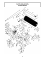
PARTS BREAKDOWN AND PARTS LIST
Rotary Broom ............................................................................................................................................ 20
Subframe ................................................................................................................................................... 25
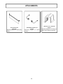
ATTACHMENTS ..................................................................................................................................................... 28
PAGE

2
INTRODUCTION
TO THE PURCHASER
This new accessory was carefully designed to give years of dependable service. This manual has been provided to
assist in the safe operation and servicing of your attachment.
NOTE: All photographs and illustrations in the manual may not necessarily depict the actual models or attachment, but
are intended for reference only and are based on the latest product information available at the time of publication.
Familiarize yourself fully with the safety recommendations and operating procedures before putting the machine to
use. Carefully read, understand and follow these recommendations and insist that they be followed by those who will
use this attachment.
THIS SAFETY ALERT SYMBOL IDENTIFIES AN IMPORTANT SAFETY MESSAGE IN THIS
MANUAL THAT HELPS YOU AND OTHERS AVOID PERSONAL INJURY OR EVEN DEATH.
DANGER, WARNING, AND CAUTION ARE SIGNAL WORDS USED TO IDENTIFY THE LEVEL OF
HAZARD. HOWEVER, REGARDLESS OF THE HAZARD, BE EXTREMELY CAREFUL.
DANGER: Signals an extreme hazard that will cause serious injury or death if recommended precautions
are not followed.
WARNING: Signals a hazard that may cause serious injury or death if the recommended precautions are
not followed.
CAUTION: Signals a hazard that may cause minor or moderate injury if the recommended precautions are
not followed.
Record your attachment serial number and purchase date in the section reserved below (there is no serial number on
the subframe). Your dealer requires this information to give you prompt, efficient service when ordering replacement
parts. Use only genuine parts when replacements are required.
If warranty repairs are required please present this registration booklet and original sales invoice to your selling dealer
for warranty service.
This manual should be kept for future reference.
Please check if you have received all the parts for your kit with the list of the
bag and the list of the box.
SERIAL NUMBER : ___________________________
(IF APPLICABLE)
MODEL NUMBER: ___________________________
PURCHASE DATE : ___________________________

3
SAFETY PRECAUTIONS
Careful operation is your best insurance against an accident. Read this section carefully before operating the vehicle
and accessory. This accessory is capable of amputating hands and feet and throwing objects. Failure to observe the
following safety instructions could result in serious injury. All operators, no matter how experienced they may be,
should read this and other manuals related to the vehicle and accessory before operating. It is the owner's legal
obligation to instruct all operators in safe operation of the accessory.
GLOSSARY:
In this manual, right and left sides are determined by
sitting on the seat of the vehicle facing forward.
In this manual, "accessories" means attachments
(snowblower, rotary broom, blade etc.) that you install
on the vehicle (lawn tractors, A.T.V. s etc).
TRAINING:
This symbol, "Safety Alert Symbol", is used
throughout this manual and on the
accessory’s safety labels to warn of the
possibility of serious injury. Please take
special care in reading and understanding
the safety precautions before operating the
vehicle and accessory.
1. Read this owner's manual carefully. Be thoroughly
familiar with the controls and proper use of the
vehicle and accessory. Know how to stop the unit
and disengage the controls quickly.
2. Never allow children to operate the vehicle nor the
accessory. Never allow adults to operate the vehicle
nor the accessory without proper instructions.
3. No one should operate the vehicle nor the
accessory while intoxicated or while taking
medication that impairs the senses or reactions.
4. Keep the area of operation clear of all people,
particularly small children and pets.
PREPARATION:
1. Thoroughly inspect the area where the accessory
is to be used and remove door mats, all foreign
objects and the like.
2. For motorized accessories, disengage all clutches
and shift into neutral before starting engine.
3. Do not operate the accessory without wearing
adequate winter outer garments. Avoid loose fitting
clothing that can get caught in moving parts. Wear
footwear that will improve footing on slippery
surfaces.
4. Handle fuel with care, it is highly flammable.
a) Use approved fuel container.
b) Never add fuel to a running engine or hot engine.
c) Fill fuel tank outdoors with extreme care. Never fill
fuel tank indoors.
d) Never fill containers inside a vehicle, or on a
truck or a trailer bed with a plastic liner. Always
place containers on the ground, away from your
vehicle, before filling.
e) When practical, remove gas-powered
equipment from the truck or trailer and refuel it
on the ground. If this is not possible, then refuel
such equipment on a trailer with a portable
container, rather than from a gasoline
dispenser nozzle.
f) Keep the nozzle in contact with the rim of the
fuel tank or container opening at all times, until
refueling is complete. Do not use a nozzle lock-
open device.
g) Replace fuel cap securely and wipe up spilled
fuel.
h) If fuel is spilled on clothing, change clothing
immediately.
5. Never attempt to make any adjustments while the
engine (motor) is running (except when specifically
recommended by manufacturer).
6. Let the vehicle and accessory adjust to outdoor
temperatures before starting to clear snow.
7. Never use an accessory without proper guards,
plates, or other safety protective devices in place
8. Always make sure to wear the appropriate safety
equipment required (glasses, muffs, mask…) for
each type of product. See operation section.
9. Always make sure of having safe traction on the
vehicle by using the recommended accessories
(chains, A.T.V. tracks, counterweights…). See
operation section.
10. Never modify the accessory or any part without
the written consent from the manufacturer.

4
OPERATION:
1. Do not put hands or feet near, under or inside rotating
parts.
2. Exercise extreme caution when operating on or
crossing gravel drives, walks or roads. Stay alert for
hidden hazards or traffic. Do not carry passengers.
3. After striking a foreign object, stop the engine (motor),
disconnect the wire from the spark plug(s) and keep
wire away to prevent accidental starting. Thoroughly
inspect the accessory for any damage and repair
damage before restarting and using the accessory.
4. If the unit should start to vibrate abnormally, stop the
engine (motor) and check immediately for the
cause. Vibration is generally a warning of trouble.
5. Take all possible precautions when leaving the
vehicle unattended. Disengage the power take-off,
lower the attachment, place the transmission into
neutral, set the parking brake, stop the engine and
remove the contact key.
6. Do not run the engine indoors, except when starting
the engine and for transporting in or out of the
building. Do not operate or let motor run in a storage
area without ventilation because gas contains
carbon monoxide which is odorless, colorless and
can cause death.
7. Never clean across the face of slopes, go from top
to bottom. Exercise extreme caution when using
equipment on slopes. Do not attempt to clear a
steep slope.
8. Never tolerate bystanders in the working zone.
Never use an accessory in the direction of
bystanders, it might throw gravel or debris that can
hurt people or damage property.
9. Never operate the accessory at high transport
speeds on slippery surfaces. Use care when
backing up.
10. Do not carry passengers.
11. Disengage power to the accessory when it is
transported or not in use.
12. Never operate the accessory without good visibility
or light.
14. Keep the accessory away from heat sources or
flames.
MAINTENANCE AND STORAGE
1. When cleaning, repairing or inspecting the vehicle
and accessory, make certain that all moving parts
have stopped. Disconnect wire from the spark
plug(s) and keep wire away to prevent accidental
starting.
2. Check all the bolts and components at frequent
intervals to make sure that they are properly
tightened.
3. Never store a motorized accessory with fuel in the
fuel tank inside a building where ignition sources are
present such as hot water and space heaters,
clothes dryers, and the like. Allow the engine to cool
before storing in any enclosure.
4. Always refer to the owner’s manual when you store
the accessory and vehicle for a prolonged or an
unspecified length of time.
5. Maintain or replace safety and instruction labels, as
necessary.
6 For winter accessories, (if applicable), let the engine
run for a few minutes after clean snow in order to
prevent the rotary parts from freezing.
7. Inspect the vehicle’s and accessory’s air filter every
day. Clean it or replace it as necessary. Change the
oil more often when working in dusty conditions.
See the vehicle’s and accessory's owner’s manual.
THIS SYMBOL MEANS
DANGER !
BECOME ALERT !
YOUR SAFETY IS INVOLVED !
SAFETY PRECAUTIONS

5
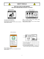
REPLACE IF DECALS ARE DAMAGED
SEE PARTS BREAKDOWN FOR DECAL LOCATION
SAFETY DECALS
To avoid injury from drive belt:
Keep hands, feet & clothing away.
Do not attempt to install or remove drive belt without
reading owner’s manual.
DECAL #105128
Before installing or using:
Locate, read and make sure to understand all of the
owner’s manual.
DECAL #105131
Refer to owner’s manual about wearing safety
glasses, ear muffs and mask.
Refer to owner’s manual for use of counter weights,
cat tracks and tire chains.
DECAL #105130
1-Do not drive faster than 3 KM/H when the rotary
broom is in operation.
2-Do not drive faster than 10 KM/H when the rotary
broom is in the raised position.
3-The sound pressure level (dBA) is measured at 1
meter from the engine (full charge at 3600 RPM).
1
2
3

6
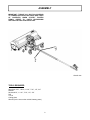
ASSEMBLY
IMPORTANT: TORQUE ALL BOLTS ACCORDING
TO TORQUE SPECIFICATION TABLE (SEE TABLE
OF CONTENTS) WHEN STATED: TIGHTEN
FIRMLY. REFER TO PARTS BREAKDOWN
SECTION FOR PART IDENTIFICATION.
Overall view
TOOLS REQUIRED
Wrenches: 9/16’’, 10mm, 1 1/16’’, 7/16’’, 1/2’’, 3/4’’
Ratchet
Sockets 9/16’’, 1 1/16’’, 7/16’’, 1/2’’, 3/4’’
Drill
1/4’’ bit
Cutting pliers
Wrench (for the nuts on the vehicle’s battery posts)

7
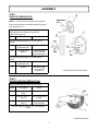
ASSEMBLY
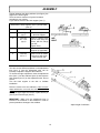
STEP 2
ROTARY BROOM PREPARATION:
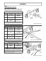
STEP 1
VEHICLE PREPARATION:
NOTE: A 1 7/8” or 50 mm tow hitch ball is required.
A) Install the lift strap (item 1) by looping it around the
suspension arm (as shown) on the vehicle.
Tighten the loop firmly.
# Item Description Action
B) Install the brackets (item 3) on both sides of
vehicle.
Bolt and nut from
suspension arm
Remove.
2-3 Flat washer and
bracket
Install and lightly
secure with the
original bolt and nut.
C) Install the brackets (item 4) on both sides of
vehicle.
Nut from
suspension arm
Remove.
4 Bracket Install and lightly
secure with the
original nut.
Choose among the three different options to prepare
your vehicle (A, B, C).
Install the lift strap or the brackets.
Install parking stands
Install a parking stand on each side of broom.
# Item Description Action
1 Parking stand
(qty 2)
Insert in stand holder.
2 Cotter pin 5/32 x 1’’
(qty 2)
Secure in top hole as
shown.
3 Hair pin 2.5mm
(Qty 2)
Secure in bottom
hole as shown.
This will allow the broom to rest on the parking
stands.

8
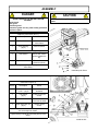
ASSEMBLY
CAUTION
Never use the Rotary Broom without the belt
guard.
DANGER
NEVER OPERATE THE ROTARY BROOM
WITHOUT:
Brush hood
Belt guard
Gear box guard
Extension guard and any other safety protection
devices in place.
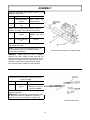
Install the push frame
Install the link
Install the push frame (item 1).
# Item Description Action
1 Push frame Insert under the
motor frame.
2 Cone bearing
(qty 2)
Insert as shown.
3 Seal washer Secure with hollow
portion towards the
top.
Tighten loosely enough to permit the push frame to
move freely.
Fill the space between the bearings with grease.
4 Nylon insert lock nut Secure from the
bottom as shown.
Install the link (item 3)
# Item Description Action
1 Hex bolt
1/4 X 1’’ (qty 2)
Insert under the lever
as shown.
2 Flat washer
(qty 2)
Install on lever as
shown.
3 Link Install one end of link
on the bolt as shown.
Tighten loosely enough to permit the parts to move
freely.
Install the other end of the link on the pivot following
the same steps as shown.
4 Nylon insert lock nut
(qty 2)
Secure link as
shown.

9
ASSEMBLY
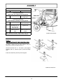
Install the wheel support
Install the assembled turnbuckles
Install broom to subframe
STEP 3
SUBFRAME PREPARATION:
NOTE: Determine according to the height of the
vehicle which set of holes to use to assemble the
wheel support (item 1) to the subframe* (See below).
Install the wheel support (item 1).
# Item Description Action
1 Wheel support Install to the
subframe.
2 Hex bolt
3/8" x 1"(qty 4)
Insert as shown.
3 Flange nut 3/8"
(qty 4)
Tighten firmly.
*The subframe must be parallel with the ground when
the subframe is installed under the vehicle.
Install the assembled turnbuckles (item 1).
# Item Description Action
1 Assembled
turnbuckle (qty 2)
Install on subframe as
shown.
2 Flat washer 3/8"
(qty 2)
Install on the
assembled
turnbuckles as shown.
3 Hex bolt
5/16" x 1"(qty 2)
Insert as shown.
4 Nylon insert lock nut
5/16" (qty 2)
Install and tighten
firmly.
NOTE: Position the chains as shown and tighten
firmly.
Install the broom to the subframe.
# Item Description Action
1 Hair pin
4mm
Remove from pin
(item 2).
2 Pin Remove as shown.
Install the broom’s push frame to the subframe.
Secure with the pin and hair pin previously removed.
NOTE: The hooked end of the pin must be inserted
into the hole to lock it in place.

10
ASSEMBLY
Choose between the three positions (see figure), the
height of the hitch support.
There must be a maximum of ground clearance
according to your vehicle.
Figure A does not have the hitch support (item 1).
Assemble the hitch supports (item 1) and the hitch
(item 3).
# Item Description Action
1 Hitch support
(qty 2)
Install the supports on
the hitch support.
2 Hex bolt
3/8’’ x 3/4’’
(qty 4)
Insert in chosen holes
(two on each side) and
secure with the flange
nuts 3/8’’.
Tighten firmly.
3 Hitch Insert on the two hitch
supports (if applicable).
4 Hex bolt
3/8’’ x 3’’
Insert in hole as shown
and secure with nylon
insert lock nut 3/8’’.
Assemble the hitch support
You have seven different positions on the adjustment
tube (item 1) (the the adjustment tube can be
inverted) to adjust the length of the subframe.
To choose the right adjustment, insert the adjustment
tube (item 1) into the subframe (item 2) and insert the
hitch support (item 3) on the adjustment tube. Do not
secure.
Turn the hitch support to the side to facilitate
installation.
Drive the vehicle over the subframe, make sure the
caster wheels do not touch the front wheels of the
vehicle.
Identify the right length and secure in place with a pin
(item 4) and 3mm hair pin (item 5).
IMPORTANT: Make sure the adjustment tube is
inserted to its maximum in the subframe in order to
prevent premature damage to the subfame.
Adjust length of subframe

11
ASSEMBLY
Install the assembled hitch support (item1) on the
vehicle’s tow hitch ball.
# Item Description Action
1 Assembled hitch
support
Insert onto the
adjustment tube.
2-3 Pin and 3mm hair
pin
Secure in place.
NOTE: The hitch support has two sets of holes to
increase the length of the subframe if necessary.
1 Assembled hitch
support
Attach on the
vehicle’s tow hitch
ball.
4-5 Pin and 3mm hair
pin
Secure.
Make sure the subframe does not come into contact
with vehicle at any time.
NOTE: You can turn the hitch assembly (item 1) by
removing the pin (item 2) to facilitate driving the
vehicle over the subframe.
WARNING : Always check that ball is completely
inserted into hitch coupler socket and that the
underjaw is securely closed around the bottom of ball.
Always check tightness before using the tow hitch. If
necessary, tighten locknut against tension spring.
Be sure hitch coupler handle is in locked position.
Secure the hitch support on the tow hitch ball
Install the turnbuckles (item 1) into the brackets or
into the lift straps.
# Item Description Action
1 Turnbuckle
(qty 2)
Adjust them so that the
subframe is centered
under the vehicle.*
*Tighten the turnbuckles firmly in order to tighten the
vehicle's suspension.
IMPORTANT: After adjusting the turnbuckles, tighten
the nuts on the vehicle’s suspension arms firmly.
Make sure to lock the nuts with the original locks.
Install the turnbuckles

12
Attach the vehicle’s winch’s hook on the bracket.
# Item Description Action
If the vehicle's winch is
higher than 20" (510mm) from the ground.
1 Sleeve Install in the top hole
of the lever.
If the vehicle's winch is
lower than 20" (510mm) from the ground.
1 Sleeve Install in the bottom
hole of the lever.
2 Hex bolt 1/2" x 2
1/4" and nylon
insert lock nut
Tigten firmly.
Vehicle’s winch’s
hook
Install on bracket as
shown.
Tip: Thread the winch’s hook behind the lever as
shown and then thread the cable over the sleeve.
ASSEMBLY
Install the winch hook
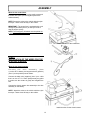
STEP 4
INSTALLATION OF THE CONTROL BOX
As shown, choose from the three different ways to
secure the control box support (item 1).
Use two hex bolts 1/4” x 1 1/2” (item 2), the support
brackets (item 4), spacers (item 3) and the flange
nuts.
Insert the control box (item 5) into the support.
Install the control box

13
ASSEMBLY
Wires for the control box:
Connect the red wire (item 1) to the positive post and
the black wire (item 2) to the negative post on the
vehicle's battery.
NOTE: Secure the wires to the vehicle with the nylon
tie wraps. These wires will stay on the vehicle.
IMPORTANT: The control box is equipped with a red
emergency kill switch (item 3) in case you need to
stop the engine quickly.
NOTE: The emergency kill switch must be pulled out
to start the engine for the broom.
Install the wires of the control box
STEP 5
INSTALLATION OF THE WIRES FOR THE
ELECTRIC STARTER:
Wires for the electric starter:
C o n n e c t t h e w i r e a s s e m b l y ( i t e m
1) on the ATV’s battery, the longest red wire (positive)
(item 1) on the positive post as shown.
Connect the black wire (negative) (item 3) on a bolt
that is on the A.T.V’s. frame (scrape away any paint
to make sure the contact is good) and retighten the
bolt.
Connect the electric starter wire assembly to the wire
assembly on the battery.
NOTE: Attach the wires to the vehicle with the nylon
tie wraps. These wires will stay on the vehicle.
Install the wires for the electric starter

14
OPERATION
WARNING
Read the vehicle owner’s manual carefully. Be
thoroughly familiar with the controls & proper
use of the attachment. Know how to stop the
accessory quickly.
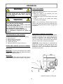
PRESSURE ON THE BRUSH ADJUSTMENT
By turning the adjustment screw (item 1) counter
clockwise, the gauge (item 2) moves higher and the
pressure of the brush on the ground increases. By
turning the adjusting screw clockwise, the gauge
(item 2) moves lower on the gear box frame and the
pressure of the brush on the ground decreases.
IMPORTANT: Adjust frequently to compensate for
brush wear. Remember to sweep with the tips of the
bristles like a broom and not with the sides of the
bristles like a mop. Too much pressure can decrease
the brush life up to 95%.
Adjust the pressure on the brush
FAMILIARISATION OF THE CONTROLS:
Familiarize yourself with the controls before using.
a) Raise the broom.
b) Start the engine (full throttle).
c) Engage the broom (item 3).
d) Lower to the ground.
e) Adjust the pressure on the brush (item 1).
ANGLE ADJUSTMENT:
In order to be able to change the angle of the broom
follow these instructions.
a) Raise the broom to its maximum (the lock
mechanism will disengage).
b) Activate the control to turn the broom to the angle
desired.
c) Lower the broom to the ground (the locking
mechanism will reengage).
NOTE: It is not necessary to perfectly align the latch
with the slots. When the broom will be lowered to the
ground the springs will allow the latch to engage itself
into the slot.
WARNING
TO PREVENT INJURIES AND FOR MORE
TRACTION WITH ROTARY BROOM:
-Do not drive faster than 3 km/hr (2 m/hr) with
rotary broom on the ground.
-Do not drive faster than 10 km/hr (6 m/hr) with
the rotary broom in raised position.
-Do not operate on a slope greater than 10°.
-A.T.V. manufacturer approved tire chains are
required.
RAISING AND LOWERING THE ROTARY BROOM:
Use the winch switch control to raise and lower the
rotary broom.
IMPORTANT: To prolong the subframe’s life, release
the switch immediately when the attachment hits the
stopper in the highest position.
IMPORTANT:
Always keep the winch cable taut when the broom is
in operation to keep the wheel support on the ground.

15
GENERAL SWEEPING
Minimize dust by reducing brush speed and by
sweeping after rain or on a day with high moisture.
SNOW SWEEPING
Adjust the gauge (item 2) to be even with the top of
gear box frame. The broom works well for light snow
removal.
Sweep with the wind blowing in the direction of broom
discharge (wind in your back).
NOTE: Foreign objects in the snow may be thrown
faster than the snow itself.
Frequently clean the snow and ice accumulation from
the top and bottom of the broom hood.
LAWN DETHATCHING AND LEAF RAKING:
Lower the broom on a hard surface and lift the brush
1" from the ground by turning the adjusting screw
clockwise. The brush is supported by dolly wheels.
This adjustment is normally satisfactory but you may
raise or lower depending upon grass height.
Low brush speed and ground speed is best for lawn
dethatching and leaf raking.
OPERATION

16
MAINTENANCE & DISMOUNTING
MAINTENANCE
a) Check oil level in gear box every fifty hours and fill to
plug level with SAE-90-EP oil when necessary.
b) Grease the wheel axles after every eight hours of
use.
c) Chain: do not lubricate when used in dusty
conditions. After use, wash clean and lubricate.
d) Adjust the chain frequently by moving the idler
sprocket to give 1/2" deflection.
e) Frequently clean the interior and exterior of hood,
dirt, mud, ice, etc, accumulation adds weight on the
brush and could result in premature wear of brush.
f) Check mounting bolts at frequent intervals for proper
tightness to be sure equipment is in safe working
conditions.
g) Apply oil at all pivot points.
h) Inspect the air filter on the vehicle and accessory
every day. Clean it or replace it when necessary.
Change the oil more often when working in dusty
conditions. See the owner's manual for the vehicle
or for the accessory.
BRUSH REPLACEMENT:
See parts breakdown section for parts identification.
a) Remove the hood.
b) Loosen the chain idler sprocket.
c) Remove the bolts from both flangettes that holds the
brush hollow shaft.
d) Remove the brush hollow shaft from the broom
frame.
e) Loosen the set screw and remove the right bearing
from the brush hollow shaft
f) Remove the bolt which retains the brush to the brush
hollow shaft.
g) Remove the brush tube from axle.
h) Install the new brush by reversing the procedure.
i) Adjust the tension on the chain by moving the idler
sprocket to give a 1/2" deflection on the length of the
chain.
BEFORE DOING ANY MAINTENANCE OR
DISMOUNTING AN ACCESSORY, REFER TO THE
SAFETY PRECAUTIONS.
CAUTION
Never use the Rotary Broom without the belt
guard.
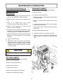
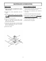
BELT REPLACEMENT:
For belt part numbers, refer to parts breakdown
section for parts identification.
a) Remove the belt guard (item 1).
b) Replace the belt (item 2).
c) Engage the accessory.
d) Make sure the pulleys are well aligned.
e) Engage and reinstall the belt guard.

17
END OF SEASON STORAGE
a) Clean the broom and inside of the hood and paint
all the parts where the paint has worn off.
b) Take note of the replacement parts needed for
next season.
c) Lubricate all grease fittings and all moving parts.
d) Store broom on parking stands. Make sure the
brush bristles never touch the ground.
e) If brush bristles are exposed to direct sunlight,
protect the bristles with a tarp.
f) Store the broom in a dry place.
DISMOUNTING
a) Select a level surface, set parking brake, stop the
engine, and remove the ignition key to prevent
accidental starting.
b) Straighten the broom perpendicular with the
vehicle.
c) Set the parking stands in their most extended
position Make sure the brush bristles never touch
the ground.
d) Lower the broom to the ground.
e) Unhook the turnbuckles from the front of the
vehicle, the hook from the winch and the hitch
from the rear of the vehicle.
f) Remove the control box (item 1) from the support
(item 2). Disconnect the wires (item 3) and place
the box on the accessory.
g) Remove the vehicle.
MAINTENANCE & DISMOUNTING

18
TROUBLESHOOTING
* Please refer to parts breakdown section for parts identification
PROBLEM POSSIBLE CAUSES CORRECTIVE ACTION
Brush wears out prematurely or
does not wear out evenly.
The brush turns jerkily.
The pressure on the brush is not
well adjusted.
Too much pressure on the brush, it
will wear out up to 5 times faster.
Reduce the pressure on the brush
when on the ground.
Adjust when needed to compensate
for the wearing out of the brush.
Always sweep with the tips of the
bristles like a broom and not with
the sides of the bristles like a mop.
Maintain the gauge even with the
top of the gear box frame or lower
when sweeping hard surfaces.
The brush does not sweep well. Debris accumulation. Clean the inside and outside of the
hood frequently during operation.
Dirt, mud, ice, etc.. accumulation
adds weight on the brush and could
result in premature wear of the
brush.
The brush is too aggressive when
lawn dethatching or leaf raking.
The brush does not turn on the
grass.
Too much pressure on the brush. Lower the broom on a hard surface
and lift brush 1" from the ground by
turning the adjusting screw
clockwise.
Adjust from time to time if
necessary.
The chain wears out prematurely.
Inappropriate lubrication. Do not lubricate the chain during
operation. Wait until the job is
finished.
Wash the rotary broom and
lubricate the chain.
Let the broom turn a few moments
so the oil penetrates in the chain.
Th e s p r o c ke t w e a r s o u t
prematurely.
Chain is not adjusted. Check the chain adjustment
frequently (too tight, too loose).
Loss of steering. Too much pressure on the brush. Reduce pressure on the brush. If
problem persists, contact your
dealer for more information.
The bristles take a bad form or
shape.
The broom was not stored on the
parking stands.
Wash the broom with warm water or
warm steam. Leave in raised
position and let it turn a few turns.
The brush should take its original
shape.
Electric motor does not work Motor overheating. These motors are equipped with an
internal protector.
Wait 10 minutes before using.
La page charge ...
La page charge ...
La page charge ...
La page charge ...
La page charge ...
La page charge ...
La page charge ...
La page charge ...
La page charge ...
La page charge ...
La page charge ...
La page charge ...
-
 1
1
-
 2
2
-
 3
3
-
 4
4
-
 5
5
-
 6
6
-
 7
7
-
 8
8
-
 9
9
-
 10
10
-
 11
11
-
 12
12
-
 13
13
-
 14
14
-
 15
15
-
 16
16
-
 17
17
-
 18
18
-
 19
19
-
 20
20
-
 21
21
-
 22
22
-
 23
23
-
 24
24
-
 25
25
-
 26
26
-
 27
27
-
 28
28
-
 29
29
-
 30
30
-
 31
31
-
 32
32


dans d''autres langues
- English: Bercomac 700448-2 User manual
Documents connexes
-
Bercomac 700448-1 Manuel utilisateur
-
-
-
-
-
-
-
-
-
