Bosch KTS 340 Original Instructions Manual
- Taper
- Original Instructions Manual

KTS 340
en
Original instructions
System tester for
control unit diagnosis
fr
Notice originale
Testeur système pour le diagnostic des
centrales de commande
es
Manual original
Comprobador de sistema para
el diagnóstico de unidades de mando


1 689 989 072 2010-06-09| Robert Bosch GmbH
4 | KTS 340 | en
Contents
1. Symbols used 5
1.1 Documentation 5
1.2 KTS 340 5
2. User information 5
2.1 Important notes 5
2.2 Safety instructions 5
2.3 Electromagnetic compatibility (EMC) 5
2.4 Disposal 5
2.5 Open Source Software 5
2.6 J2534 Reprogramming, web browser 5
2.7 WLAN (Wireless Local Area Network) 6
2.7.1 Important information on WLAN 6
2.7.2 Information on access points 6
2.7.3 Information on WLAN for USA and
Canada 6
3. Product description 7
3.1 Use 7
3.2 System requirements 7
3.3 Scope of delivery 7
3.4 Special accessories 7
3.5 Description of the unit 8
3.6 USB adapter 8
3.7 LED status 8
3.7.1 Battery charge LED 8
3.7.2 WLAN LED 8
4. Commissioning 9
4.1 Connection 9
4.2 Licensing with the
ESI[tronic] Startcenter 9
4.2.1 Installing the ESI[tronic] Startcenter 9
4.2.2 Licensing the KTS 340 online 11
4.2.3 Licensing the KTS 340 by fax 13
4.2.4 KTS 340 fax licensing procedure 13
5. Operation 13
5.1 Connection to the vehicle 13
5.2 Switching on 14
5.3 Switching off 14
5.4 Notes on multimeter 14
5.5 Touchscreen with stylus 14
5.6 Program description 14
5.7 Software update 15
5.7.1 Online software update
(from ESI[tronic] Startcenter
version 2010/2) 15
5.7.2 Software update using the
ESI[tronic] DVD 15
5.8 Faults 15
6. Maintenance 16
6.1 Cleaning 16
6.2 Rechargeable battery replacement 16
6.3 Spare and wearing parts 16
7. Technical data 17
7.1 General data 17
7.2 Interface protocols 17
7.3 Power supply unit 17
7.4 Multimeter specifications 17
7.4.1 DC measurement (CH1 and CH2) 17
7.4.2 Measurement of AC and rms value
(CH1 and CH2)
*)
17
7.4.3 Resistance measurement (CH1) 17
7.4.4 Current measurement (CH1 and CH2) 18
7.4.5 Continuity tester (CH1) 18
7.4.6 Diode measurement (CH1) 18
7.5 WLAN 18

1 689 989 072 2010-06-09| Robert Bosch GmbH
Symbols used | KTS 340 | 5KTS 340 | 5 | 5
en
1. Symbols used
1.1 Documentation
Pictograms linked with the key words Danger, Warning
and Caution are warnings and always indicate an imme-
diate or potential hazard to the user.
Danger!
Immediate danger that could cause serious
personal injury or death.
Warning!
Potentially dangerous situation that could
cause serious personal injury or death.
Caution!
Potentially dangerous situation that could
cause personal injury or damage to property.
! Important – warns of a potentially hazardous situa-
tion in which the KTS 340, the test sample or other
object in the vicinity could be damaged.
In addition to these warnings, the following symbols are
also used:
i Info – Details for the application and further useful
information.
¶ Single-step procedure – instructions for a procedure
that can be completed in just one step.
? Intermediate result – an intermediate result is dis-
played during a procedure.
"Final result – the final result is displayed at the end
of the procedure.
1.2 KTS 340
Disposal
Old electrical and electronic devices, including
cables and accessories or batteries must be
disposed of separate to household waste.
2. User information
2.1 Important notes
Important information on copyright, liability and warranty
provisions, as well as on equipment users and company
obligations, can be found in the separate manual "Important
notes on and safety instructions for Bosch Test Equipment".
These instructions must be carefully studied prior to start-
up, connection and operation of the KTS 340 and must
always be heeded.
2.2 Safety instructions
All the pertinent safety instructions can be found in the
separate manual "Important notes on and safety instruc-
tions for Bosch Test Equipment". These instructions
must be carefully studied prior to start-up, connection
and operation of the KTS 340 and must always be heed-
ed.
2.3 Electromagnetic compatibility (EMC)
The KTS 340 is a class B product as per EN 61 326.
2.4 Disposal
This KTS 340 is subject to European guideli-
nes 2002/96/EG (WEEE).
Old electrical and electronic devices, including-
cables and accessories or batteries must be
disposed of separate to household waste.
¶ Please use the return and collection sys-
tems in place for disposal in your area.
¶ Damage to the environment and hazards to
personal health are prevented by properly
disposing of KTS 340.
2.5 Open Source Software
A list of the open source software licenses for the
KTS 340 can be found in an Adobe PDF document on
the “ESI[tronic] Startcenter” DVD.
Caution – Hot charging contacts
Risk of burns if touched.
¶ Do not touch charging contacts.
2.6 J2534 Reprogramming, web browser
i The " (Info) >> Help" menu in the Online Help
contains all the necessary information on J2534
Reprogramming and the web browser.

1 689 989 072 2010-06-09| Robert Bosch GmbH
6 | KTS 340 | Symbols useden
2.7 WLAN (Wireless Local Area Network)
2.7.1 Important information on WLAN
WLAN stands for Wireless Local Area Network. As
with Bluetooth, WLAN provides a radio link on the free
2.4 GHz ISM band (ISM: Industrial, Scientific, Medical).
This frequency range is subject to government regula-
tions, but may be used without a license in most coun-
tries. Consequently a large number of applications and
devices employ this frequency band for transmission.
This can result in frequency interference.
Depending on ambient conditions, the WLAN link may
therefore deteriorate, e.g. in the case of Bluetooth links,
cordless telephones, radio-controlled thermometers,
radio-controlled garage door openers, radio-controlled
light switches or radio-controlled alarm systems.
i Bluetooth can lead to interference in the bandwidth
of the WLAN network. The antennas of Bluetooth
and WLAN devices should be at least 30 centimeters
apart. Do not plug Bluetooth USB adapters and WLAN
sticks into adjacent USB slots on PCs/laptops. Use
the USB extension cable (special accessory) to main-
tain a distance between the Bluetooth USB adapter
and the WLAN stick on the PC/laptop.
i Exercise extreme caution if wearing pacemakers
or other vital electronic devices when using radio
systems, as proper functioning of these items could
be impaired.
Note the following to ensure the best possible connec-
tivity:
R The WLAN radio signal always tries to find the most
direct path. When setting up the PC/laptop and ac-
cess point (see section 2.6.2), make sure there are
as few obstacles as possible (e.g. steel doors and
concrete walls), which could interfere with the radio
signal from and to the KTS 340. Inside buildings, the
range of the WLAN is also greatly influenced by the
construction materials used. Conventional masonry,
wooden walls and certain types of dry construc-
tion wall scarcely impede radio waves. Thin gypsum
walls can however cause problems, as considerable
amounts of moisture may accumulate in the gypsum
and result in the absorption of radio signals. Concrete
(and in particular reinforced concrete) largely blocks
out radio waves. Cellar ceilings are often impenetra-
ble. Generally speaking, walls with a lot of installed
metal (e.g. pipes, wires) obstruct radio waves.
R Radio reception is also impeded by large metal
objects such as radiators and window frames as
well as active sources of interference such as DECT
telephones and microwave ovens.
R Have your network infrastructure installed and
tested in advance by a data systems expert.
R Keep the SSID and the codes for the radio link in a
safe place. Make sure these data are readily to hand
in case faults occur.
R We recommend a thorough inspection of the pre-
mises on commissioning: Establish where in the
building the KTS 340 works properly and where the
operating limits are.
R If the KTS 340 is to be used in a vehicle (Faraday
cage), radio communication can be severely limited.
R The radio link is affected by weather conditions. The
reception signal may therefore vary.
R Please contact your network administrator with any
queries.
2.7.2 Information on access points
A wireless access point is an electronic device, which
acts as an interface between a radio network and a
cable-connected computer network. It provides a wire-
less connection between the KTS 340, the PC/laptop
with ESI[tronic] Startcenter and a printer, for example.
i We recommend using WLAN standard IEEE 802.11g
(data transmission rate max. 54 Mbps) for the access
point. The "extended range" function is not supported.
Please note the following:
R The access point should be located as centrally and
high up as possible, ideally under the ceiling.
R The access point antenna should face downwards
towards the floor.
R In the event of a poor connection it may be useful to
change the set channel on the access point. If pos-
sible, avoid using neighboring channels to channels
that are already in use.
R We recommend that encryption of radio communica-
tions is configured at the access point.
2.7.3 Information on WLAN for USA and Canada
USA:
Changes or modifications not expressly approved by
the party responsible for compliance could void the
user’s authority to operate the equipment.
Canada:
Operation is subject to the following two conditions:
R this device may not cause interference, and
R this device must accept any interference, including
interference that may cause undesired operation of
the device.
This Class [B] digital apparatus complies with Canadian
ICES-003.

1 689 989 072 2010-06-09| Robert Bosch GmbH
Product description | KTS 340 | 7KTS 340 | 7 | 7 en
3. Product description
3.1 Use
The KTS 340 is a system tester for control unit diag-
nosis, trouble-shooting, repair and service in auto-
motive workshops. The functions of the KTS 340 with
licensed ESI[tronic] are as follows:
R Vehicle identification
R Vehicle information
R Diagnosis
R Service information
R Maintenance
i The KTS 340 is designed for operation in the WLAN
2.4 GHz for USA, Canada and Mexico.
The device satisfies the requirements of the R&TTE
(Radio Equipment and Telecommunications Terminal
Equipment) Directive, as confirmed by the CE mark.
! The KTS 340 is a precision device, which is not to
be subjected to sources of heat (e.g. direct sun-
light), impact, vibration, magnetic fields and exces-
sive soiling. The KTS 340 may only be opened for
changing the battery (the battery referred to in this
manual is a rechargeable battery).
3.2 System requirements
A PC/laptop with WIN XP (SP2), WIN Vista
TM
Home
Premium, WIN Vista
TM
Business or WIN 7 operating
system and at least one free USB port is required for
KTS 340 licensing using the ESI[tronic] Startcenter and
the software update for KTS 340 control unit diagnosis.
The USB port must support the USB 2.0 or USB 1.1
protocol.
3.3 Scope of delivery
Description Order number
KTS 340
Power supply unit
Power supply lead
1 687 022 890
1 684 461 161
USB connecting cable, 3 m 1 684 465 562
OBD diagnostic cable, 3 m 1 684 465 557
UNI connecting cable, 4 core 1 684 463 539
Stylus (3x) 1 683 083 007
USB adapter 1 681 335 117
ESI[tronic] Startcenter DVD 1 987 P12 034
KTS 340 Getting Started DVD 1 687 370 308
Case 1 685 438 626
Measuring lead, red 1 684 430 065
Measuring lead, blue 1 684 430 066
Measuring lead, yellow 1 684 430 067
Ground cable, black 1 684 430 068
Test prod, red (2x) 1 684 485 035
Connection terminal, black 1 684 480 022
Important information and safety instructions 1 689 985 000
KTS 340 operating instructions 1 689 989 072
KTS 340 Quick Start Guide 1 689 989 075
EU Declaration of conformity 1 689 974 307
! Always store the KTS 340 and accessories in the
case when not in use.
3.4 Special accessories
Information on special accessories, such as vehicle-
specific connecting cables, can be obtained from your
authorized Bosch dealer.

1 689 989 072 2010-06-09| Robert Bosch GmbH
8 | KTS 340 | Product descriptionen
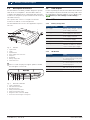
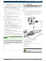
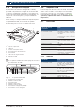
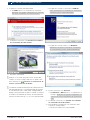
3.5 Description of the unit
The KTS 340 is a modular, portable diagnostic system
that can be used anywhere. The KTS 340 features a
computer unit with memory card and an 8.4 inch LCD
touchscreen. ESI[tronic] is pre-installed on the memory
card at the factory.
The operator has a choice of a stylus for the LCD
touchscreen and an on-screen keyboard.
The KTS 340 and accessories are supplied in a protec-
tive case.
KTS 340
Powered b
y ESI tronic
ax. 28 Vm
459843-5K
1
8
7
6
5
4
3
2
Fig. 1: KTS 340
1 Stylus holder
2 Stylus
3 On/Off button
4 Power supply unit connection
5 USB port
6 WLAN LED
7 Battery charge LED
8 LCD touchscreen
! There is a risk of injury from glass splinters should
the LCD glass cover break.
CH2
ax. 60 Vm
DIAG
CH1
K
459843_1Ko
1
7
543
2 6
Fig. 2: Rear view of KTS 340
1 Stylus compartment
2 CH2 measurement input
3 Ground connection
4 CH1(-) measurement input
5 CH1(+) measurement input
6 Diagnostic cable connection (DIAG)
7 Connection for Kensington security lock
3.6 USB adapter
For direct printing via USB, the KTS 340 must be linked to
a Bosch-approved printer via USB connecting cables and
the USB adapter (USB-A/A adapter) (refer to Online Help:
"
(Service) >> User settings >> Print settings").
3.7 LED status
3.7.1 Battery charge LED
Battery charge LED Status
Green light Battery fully charged, external
power supply connected.
Flashing green Battery fully charged, external
power supply not connected.
Yellow light Battery being charged, external
power supply connected.
Flashing yellow Battery almost flat, connect
external power supply.
Red light Fault on charging.
Flashing red Battery flat (KTS 340 will be
switched off within 2 minutes),
connect external power supply.
3.7.2 WLAN LED
WLAN LED Status
Green light WLAN is configured and KTS 340
is connected to an access point,
field strength good.
Yellow light
WLAN is configured and KTS 340
is connected to an access point,
field strength poor.
Red light
WLAN is configured, KTS 340 is
not connected to an access point.
Off WLAN is not configured.

1 689 989 072 2010-06-09| Robert Bosch GmbH
Commissioning | KTS 340 | 9KTS 340 | 9 | 9 en
4. Commissioning
4.1 Connection
Prior to commissioning, make sure the mains voltage
matches the voltage specified on the power supply unit
(use the power supply lead provided).
4.2 Licensing with the
ESI[tronic] Startcenter
The KTS 340 is supplied pre-installed and pre-licensed
and can be used immediately for control unit diagnosis.
The KTS 340 has to be re-licensed to be able to utilize
the functions detailed in the purchase contract and to
implement further updates. The customer number and
password required for this can be found on the delivery
note.
! Do not connect the KTS 340 to the PC/laptop until
prompted to do so during the installation routine.
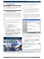
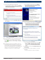
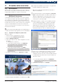
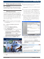
4.2.1 Installing the ESI[tronic] Startcenter
Procedure:
1. Close all open applications.
2. Insert the "ESI[tronic] Startcenter" DVD.
3. Open the "Windows Explorer".
4.
Start D:\setup.exe (D = DVD drive).
? Setup commences.
? The following message appears with WIN Vista:
An unidentified program is attempting
to access the computer.
? The following message appears with WIN 7:
Do you wish to allow changes to be
made to this computer by the fol-
lowing program?
5. Confirm the message with "Allow" or "Yes".
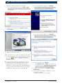
6. Select the installation language and confirm with <OK>.
i The selected installation language will also be the
language used in the ESI[tronic] Startcenter.
7. Follow the on-screen instructions.
i Select the country in which the KTS 340 is to be
used in the "Country selection" installation menu.
The dialog box does not appear if a country was
already selected during an earlier installation of
Startcenter (e.g. with KTS 200).
i If Adobe Reader is not yet installed on the PC/laptop,
it will be installed at the end of the ESI[tronic] Start-
center installation routine. Adobe Reader is required
to display the KTS 340 control unit diagnosis logs on
the PC/laptop.
i We recommend that you only install the KTS data
packet on the hard disk if you wish to update several
KTS units. Then, the ESI[tronic] Startcenter DVD will
not be required for update.
? The following message appears with WIN Vista:
Do you wish to install this device
software?
8. Confirm the message with "Install".

1 689 989 072 2010-06-09| Robert Bosch GmbH
10 | KTS 340 | Commissioning en
9. Disconnect the USB link to the KTS 340.
? The following message then appears with WIN 7:
Windows can't verify the publisher of
this driver software
.
10. Confirm the message with "Install this driver soft-
ware anyway".
11. Switch on the KTS 340.
i The KTS 340 always starts up in English (US) when
first switched on. The language can be changed
under "
(Service) >> User setting >> Language
setting".
i The ESI[tronic] Startcenter installation routine au-
tomatically installs the USB driver to permit commu-
nication between the KTS 340 and the PC/laptop.
The "Connect USB" dialog box does not appear if the
USB driver was already installed during an earlier
installation of Startcenter (e.g. with KTS 200).
? The following message appears with WIN XP:
This wizard helps you install soft-
ware for: KTS-embedded.
? The following message appears with WIN Vista:
Windows needs to install driver
software for your KTS embedded.
12. Close the message with "Cancel".
? The following message then appears with WIN
Vista and WIN 7:
Windows can't verify
the publisher of this driver soft-
ware.
13. Confirm the message with "Install this driver soft-
ware anyway".
14. To successfully conclude installation, restart the
PC/laptop.
? ESI[tronic] Startcenter has been installed.

1 689 989 072 2010-06-09| Robert Bosch GmbH
Commissioning | KTS 340 | 11KTS 340 | 11 | 11 en
15. Start the "ESI[tronic] Startcenter".
i The " (Info) >> Help" menu opens the online
help. This contains all essential information on the
ESI[tronic] Startcenter.
16. Perform KTS 340 licensing by fax or online.
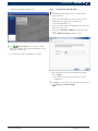
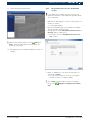
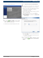
4.2.2 Licensing the KTS 340 online
! A PC/laptop with Internet access is required for
online licensing.
1. Connect the KTS 340 to the mains voltage via the
supplied power supply unit, and switch on.
? The KTS 340 starts up.
2.
Connect the KTS 340 to a PC/laptop by means of the
USB connecting cable.
3. Select the "Licensing >> Online" menu in the Start-
center.
? The "Online licensing" input box opens.
4. Step 1: Enter the customer number/password and
select <Login>.
? The Internet connection for online licensing is
established.
i If "Login" is not possible, check proxy settings under
"
(Service) >> User settings".

1 689 989 072 2010-06-09| Robert Bosch GmbH
12 | KTS 340 | Commissioning en
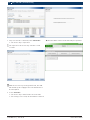
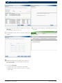
5. Step 2: Select the contract ID, then <Generate>.
? The license key is requested.
i The request for the license key can take several
seconds.
! While the license key is being transferred, the USB
link and the power supply to the KTS 340 must not
be interrupted.
6. Select <Execute>.
? The license key is transferred to the KTS 340.
? If licensing is successful, the KTS 340 is restarted.
"The KTS 340 is now licensed and ready for operation.

1 689 989 072 2010-06-09| Robert Bosch GmbH
Commissioning | KTS 340 | 13KTS 340 | 13 | 13 en
4.2.3 Licensing the KTS 340 by fax
1. Select the "Licensing >> Fax" menu in the Start-
center.
? The "License request" input box is opened.
2. Step 1: Enter company data.
3. Step 2: Select country for license request.
4. Step 3: Enter ID number and print out licensing
form.
5. Sign licensing form and submit by fax.
4.2.4 KTS 340 fax licensing procedure
Once you have received the license key by fax, you need
to perform the actual licensing.
1. Connect the KTS 340 to the mains voltage via the
supplied power supply unit, and switch on.
? The KTS 340 starts up.
2.
Connect the KTS 340 to a PC/laptop by means of the
USB connecting cable.
3. Click the "Licensing >> Licensing procedure" menu
in the Startcenter.
? The "License request" input box opens.
4. Enter the customer number, ID number and license
key.
5. Perform licensing.
? The license key is transferred.
? If licensing is successful, the KTS 340 is restarted.
"The KTS 340 is now licensed and can be used for control
unit diagnosis.
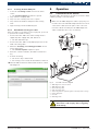
5. Operation
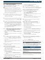
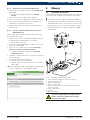
5.1 Connection to the vehicle
The KTS 340 is designed for operation on vehicles with
a battery voltage of 12 V and 24 V.
! Make sure the OBD diagnostic cable is properly con-
nected to the KTS 340 and firmly attached. Incorrect
connection could cause the pins of the connector
to bend or break off. Only use the OBD diagnostic
cable contained in the scope of delivery.
1
2
3
4
5
6
7
8
9
10
11
12
13
14
15
16
1
3
2
7
6
CH2
ax. 60 V
m
DIAG
K
CH1
KTS 34
0
Powered by ESI tr
onic
459843
8
5
4
Fig. 3: KTS 340 connection diagram
1 OBD diagnostic socket in vehicle
2 OBD diagnostic cable
3 UNI connecting cable
4 USB connecting cable
5 Connecting cable for cigarette lighter socket (special accessory)
6 Power supply unit
7 KTS 340
8 Measuring leads
Placing the KTS 340 on the steering wheel
will lead to a risk of injury due to triggering
of the airbag.

1 689 989 072 2010-06-09| Robert Bosch GmbH
14 | KTS 340 | Operationen
The KTS 340 is connected to the diagnostic interface in
the vehicle by means of:
R The OBD diagnostic cable (Fig. 3, Pos. 2), or
R The OBD diagnostic cable and also the UNI connect-
ing cable (Fig. 3, Pos. 3; special accessory), or
R The OBD diagnostic cable and also a vehicle-specific
adapter cable (special accessory), or
R A vehicle-specific adapter cable
(special accessory).
5.2 Switching on
¶ Switch on the KTS 340 with the On/Off button.
"After the system has started, the KTS 340 remains
in the "Vehicle identification" start screen. The start
screen is always displayed after switch-on.
! If the KTS 340 is supplied with power via the power
supply unit, always use the power supply unit
provided. Do not use power supply units with less
power than 15V/3A, such as those supplied with the
KTS 200 or KTS 5xx, for example.
The KTS 340 is usually supplied with power via the
OBD diagnostic socket in the vehicle. If you do not
know where in the vehicle the OBD diagnostic socket is
located, we recommend finding it by means of KTS 340
control unit diagnosis.
i In some vehicles, the cigarette lighter socket only
supplies power when the ignition is turned on.
i If a test step involves starting the engine, the battery
voltage may drop to such an extent that supply via
the vehicle is no longer guaranteed. In such cases
it may be necessary to supply the KTS 340 via the
power supply unit.
i In some vehicles, the ignition must be switched on in
order for power to be supplied via the OBD interface.
If the KTS 340 is connected to a PC/laptop via the USB
connecting cable, we recommend supplying it with
power via the power supply unit provided.
5.3 Switching off
¶ Press the On/Off button for approx. three seconds.
"The KTS 340 is switched off.
If it is only being run off the battery, the KTS 340 is
switched off if the battery voltage drops below 8 V or if
the device has not been used for ten minutes (factory
setting).
If the KTS 340 is being supplied via an external power
source (e.g. OBD diagnostic cable or power supply
unit) and is not used for a lengthy period, the bright-
ness of the LCD touchscreen is reduced.
5.4 Notes on multimeter
Danger from high voltage!
There is a risk of potentially fatal voltage if
measurements are taken without a ground
cable.
¶ If no diagnostic cable is connected, use the
ground cable provided to make a ground
connection between the KTS 340 and ve-
hicle ground before taking U, R or I measu-
rements.
¶ Connect the ground cable as close as pos-
sible to the object to be measured.
¶ Only use the KTS 340 on the vehicle and not
for measurements involving voltages > 60 V.
¶ Do not perform any measurements on igni-
tion systems.
¶ Only use the test cables provided (with
contact protection).
¶ Always plug in the test cables at the
KTS 340 first and then on the vehicle.
¶ Do not lay unshielded test cables close
to sources of major interference such as
ignition cables.
5.5 Touchscreen with stylus
The touchscreen of the KTS 340 is operated with the
stylus. Touch the application you require with the
stylus.
i You can perform "Touchscreen calibration" in the
Service menu
via "User settings >> Customer
Service". To avoid errors, your eyes must be vertical-
ly above the calibration points. Click on the calibra-
tion points as accurately as possible.
5.6 Program description
You can open the online help for the KTS 340 in the
header bar under
.
You can find basic information on the KTS 340 and
the ESI[tronic] Startcenter in the "ESI[tronic] trainer".

1 689 989 072 2010-06-09| Robert Bosch GmbH
Operation | KTS 340 | 15KTS 340 | 15 | 15 en
5.7 Software update
The software update is performed either using the
"ESI[tronic] Startcenter" DVD or "Online".
! Only perform the software update for a licensed
KTS 340. The USB link and the power supply to the
KTS 340 must not be interrupted during the software
update. In addition, Standby mode on the PC/laptop
must be deactivated.
i The ESI[tronic] Startcenter DVD 1 (annual basic ver-
sion) must be installed using the "Software update
by way of DVD" function.
i You can find the online help for the software update
in the ESI[tronic] Startcenter under "Help >> Help".
i If the software update of the KTS 340 was aborted
(e.g. USB link was interrupted) or installation was
incomplete, you can perform a recovery in the
ESI[tronic] Startcenter under "Help >> Customer
Service" in the menu "
Restore KTS software" (see
ESI[tronic] Startcenter online help).
5.7.1 Online software update (from ESI[tronic]
Startcenter version 2010/2)
1. Start the "ESI[tronic] Startcenter".
2. Open the "Settings >>Online updates" input box.
3. Enter the customer number and password and select
<Next>.
i If "Login" is not possible, check proxy settings under
"Settings >> User settings".
4. Select an available update and start the software
update.
5. Follow the on-screen instructions.
i To successfully conclude installation, restart the
PC/laptop.
KTS 340 software update
1. Disconnect the power supply unit and USB connect-
ing cable from the KTS 340.
2. Start the "ESI[tronic] Startcenter".
3.
Supply power to the KTS 340 once more with the
power supply unit.
? The KTS 340 starts up.
? The start screen "Vehicle identification" appears.
4.
Connect the KTS 340 to a PC/laptop by means of the
USB connecting cable.
5. ESI[tronic] Startcenter: Open "
KTS 340 >> Device
information".
6. Select an available update
7. Select <Update>.
"The system software is installed on the KTS 340.
5.7.2 Software update using the ESI[tronic] DVD
Step 1: Installing ESI[tronic] Startcenter
1. Close all open applications.
2. Insert the "ESI[tronic] Startcenter" DVD.
3. Open the "Windows Explorer".
4.
Start D:\setup.exe (D = DVD drive).
? Setup commences.
5. Follow the on-screen instructions (see section 4.2.1).
i To successfully conclude installation, restart the
PC/laptop.
Step 2: KTS 340 software update
1. Disconnect the power supply unit and USB connect-
ing cable from the KTS 340.
2. Start the "ESI[tronic] Startcenter".
3.
Supply power to the KTS 340 once more with the
power supply unit.
? The KTS 340 starts up.
? The "Vehicle identification" dialog box appears.
4.
Connect the KTS 340 to a PC/laptop by means of the
USB connecting cable.
5. ESI[tronic] Startcenter: Open "
KTS 340 >> Device
information".
6. Select an available update
i If no "available update" is displayed, the KTS 340
already has the current software and does not need
to be updated.
7. Select <Update>.
"The system software is installed on the KTS 340.
5.8 Faults
No communication with the control unit
The fault message "No system found" appears during
control unit diagnosis.
Possible causes Action to be taken
Incorrect cable
connected.
Check that the correct cable has been
used.
Wrong pin selected in
pin selection menu.
Check which pin must be used in "Diag-
nostic socket".
i If problems of a different nature occur, please con-
tact the ESI[tronic] Service Hotline directly.

1 689 989 072 2010-06-09| Robert Bosch GmbH
16 | KTS 340 | Maintenanceen
6. Maintenance
6.1 Cleaning
Only clean the housing and display of the KTS 340 with
a soft cloth and neutral cleaning agents. Do not use
abrasive cleaning agents or coarse workshop cloths.
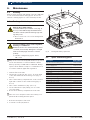
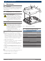
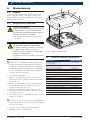
6.2 Rechargeable battery replacement
Danger due to high voltage!
If the KTS 340 is open and the cover (Fig. 4,
Pos. 5) of the LCD background illumination
has been removed, life-threatening high volt-
age may occur.
¶ Never remove the cover of the background
illumination.
Incorrect handling carries a risk of ignition,
bursting or combustion!
Batteries must not be heated, burned, short-
circuited, mechanically damaged or charged
with excessively high currents or reverse
polarity.
¶ Suitable extinguishing agents: Water,
CO
2
, sand.
! Only use the nickel-metal hydride batteries specified
for the KTS 340. We recommend batteries with a
battery capacity of 2000 mAh to 2300 mAh. Always
replace all the batteries. Dispose of old batteries in
accordance with the applicable legislation.
1. Switch off the KTS 340.
2. Slacken the screws (5x, Fig. 4, Pos. 1) on the back
of the unit and detach the housing cover (Fig. 4,
Pos. 2).
3. Take out the battery compartments on the left and
right and set down on the metal housing (Fig. 4,
Pos. 3).
4. Take out the old batteries (Fig. 4, Pos. 4).
5. Insert new batteries (8x), taking care to ensure
correct polarity.
6. Re-insert the battery compartments in the unit.
! Take care not to trap the leads to the battery com-
partment when fitting the back panel.
7. Re-fit the back panel of the unit.
8. Screw the screws (5x) back in.
Best.-Nr.: 1 687 023 436
Best.-Nr.: 0 684 400 340
Typ: KTS 340
Serien-:Nr
.
FD: 2008-04 U(V);8
-28 DC
P(W): 20
PMade in Germany Robert Bosch GmbH D-73207 Plochingen
F(Hz):
430003520
FD; 2008-04
BOSCH
BOS
CH
ax. 28 Vm
459843-3Ko
1
4
3
2
3
4
5
Fig. 4: Rechargeable battery replacement
6.3 Spare and wearing parts
Description Order number
System tester KTS 340 (green) 1 687 023 549
Power supply unit
Power supply lead
1 687 022 890
1 684 461 161
USB connecting cable, 3 m 1 684 465 562
OBD diagnostic cable, 3 m
<)
1 684 465 557
4-pole UNI connecting cable
<)
1 684 463 539
Stylus (3x) 1 683 083 007
USB adapter 1 681 335 117
Case 1 685 438 626
Measuring lead, red
<)
1 684 430 065
Measuring lead, blue
<)
1 684 430 066
Measuring lead, yellow
<)
1 684 430 067
Ground cable, black
<)
1 684 430 068
Test prod, red (2x)
<)
1 684 485 035
Connection terminal, black
<)
1 684 480 022
Adapter insert 1 688 000 355
Batteries (8x) 1 687 335 031
<)
Wearing part

1 689 989 072 2010-06-09| Robert Bosch GmbH
Technical data | KTS 340 | 17KTS 340 | 17 | 17 en
7. Technical data
7.1 General data
Property Value/Range
Operating voltage 11 VDC — 34 VDC
Power consumption approx. 50 W
LCD 8.4"
800 x 600 pixels
Dimensions (L x W x H)
235 x 290 x 67 mm
9.25 x 11.42 x 2.64 inch
Weight (without connecting cables) 2100 g
4.6 lb
Operating temperature 5 °C – 40 °C
41 °F – 104 °F
Relative humidity 90 % (at 25 °C)
Degree of protection IP 40
7.2 Interface protocols
The following interfaces and their associated protocols
are supported for control unit diagnosis in compliance
with ISO 15031:
R ISO/DIS 15765-4 (CAN) - baud rates: 250 kbit/s and
500 kbit/s)
R ISO 9141-2 Fast
R ISO/DIS 14230-4 (keyword protocol 2000) 5 bauds
R ISO/DIS 14230-4 (keyword protocol 2000) Fast
R ISO/DIS 11519-4 (SAE J1850) PWM
R ISO/DIS 11519-4 (SAE J1850) VPW
7.3 Power supply unit
Property Value/Range
Input voltage 100 VAC — 240 VAC
Input frequency 50 Hz — 60 Hz
Output voltage 15 V
Operating temperature 0 °C — 40 °C
7.4 Multimeter specifications
R CH1 zero potential (blue input may be connected to
live measurement points). Input resistance
> 900 kohms.
R CH2 non-floating (black ground input must be
connected to vehicle ground). Input resistance
> 900 kohms.
7.4.1 DC measurement (CH1 and CH2)
Property Value/Range
Measuring range 200 mV — 60 V
Accuracy of CH1 ±0.75 % of measured value,
plus ±0.25 % of measuring range
Accuracy of CH2 ±2 % of measured value,
plus ±0.5 % of measuring range
Resolution 100 µV — 100 mV
(depending on measuring range)
7.4.2 Measurement of AC and rms value
(CH1 and CH2)
*)
Property Value/Range
AC frequency range 10 Hz — 400 Hz (-3 dB)
Measuring range 200 mV — 60 V
AC accuracy at 100 Hz
rms accuracy at ≤ 100 H
±2 % of measured value, plus
±0.5 % of measuring range
Resolution 100 µV — 100 mV (depending
on measuring range)
*)
The measuring ranges in measurement modes "U" and "I" are
specified as peak-to-peak values. Consequently, the digital
display box is "grayed out" if the set measuring range is briefly
exceeded (overload).
7.4.3 Resistance measurement (CH1)
Property Value/Range
Measuring range 100 — 1 M
Accuracy up to 200 K ±0.75 % of measured value
plus ±0.25 % of measuring ran-
ge
Accuracy up to 1 M ±2 % of measured value
plus ±0.25 % of measuring ran-
ge
Resolution 0.1 — 1000 (depending on
measuring range)
Input resistance > 9 M

1 689 989 072 2010-06-09| Robert Bosch GmbH
18 | KTS 340 | Technical dataen
7.4.4 Current measurement (CH1 and CH2)
Sensor Measuring range
Shunt (CH1 only) ±600 mA
30 A clamp (CH1 only) ±30 A
100 A clamp ±100 A
600 A clamp ±600 A
1000 A clamp (CH1 only) ±1000 A
7.4.5 Continuity tester (CH1)
Property Value/Range
Measurement current 2 mA
No-load voltage ≤ 5 V
Continuity < 10 (with acoustic check-back)
7.4.6 Diode measurement (CH1)
Property Value/Range
Measurement current 2 mA
No-load voltage ≤ 5 V
Maximum diode voltage 2 V
7.5 WLAN
Standard: IEEE 802.11g (54 Mbit/s), compatible with
IEEE 802.11b (11 Mbit/s), data encryption: OPEN, WPA,
WPA-PSK, WPA2, WPA2-PSK, WEP (64/128/256 bits),
antenna: -3dBi.
Radio link
KTS 340 to PC/laptop
Minimum range
Workshop environment with clear view
of access point
30 meters
In vehicle interior with vehicle door or
window open and engine running
10 meters
The range of the WLAN varies considerably.
20–40 m can normally be achieved indoors and up to
100 m outdoors.
Under adverse conditions the effective range may only
be 10–15 m or even less.
The KTS 340 automatically adapts the transmission
rate in the WLAN to the transmission conditions. In the
event of a poor radio link the data are transmitted
more slowly than with a good link.


1 689 989 072 2010-06-09| Robert Bosch GmbH
20 | KTS 340 | fr
Sommaire
1. Symboles utilisés 21
1.1 Documentation 21
1.2 KTS 340 21
2. Consignes d'utilisation 21
2.1 Remarques importantes 21
2.2 Consignes de sécurité 21
2.3 Compatibilité électromagnétique (CEM) 21
2.4 Elimination 21
2.5 Logiciel Open Source 21
2.6 J2534 Reprogramming, browser Web 21
2.7 WLAN (Wireless Local Area Network) 22
2.7.1 Remarques importantes sur WLAN 22
2.7.2 Remarques sur la borne d'accès 22
2.7.3 Remarques sur WLAN pour le Canada 22
3. Description du produit 23
3.1 Application 23
3.2 Conditions préalables 23
3.3 Fournitures 23
3.4 Accessoires spéciaux 23
3.5 Description de l'appareil 24
3.6 Adaptateur USB 24
3.7 Etat des LED 24
3.7.1 LED état de charge de l'accumulateur 24
3.7.2 LED WLAN 24
4. Première mise en service 25
4.1 Raccordement 25
4.2 Enregistrement de la licence avec
ESI[tronic] Startcenter 25
4.2.1 Installation de ESI[tronic] Startcenter 25
4.2.2 Enregistrement de la licence
du KTS 340 en ligne 27
4.2.3 Enregistrement de la licence
du KTS 340 par télécopie 29
4.2.4 Enregistrer la licence du KTS 340
par télécopie 29
5. Utilisation 29
5.1 Raccordement au véhicule 29
5.2 Mise en marche 30
5.3 Mise à l’arrêt 30
5.4 Remarques relatives au multimètre 30
5.5 Ecran tactile avec stylo tactile 30
5.6 Description du programme 30
5.7 Mise à jour du logiciel 31
5.7.1 Mise à jour du logiciel en ligne
(à partir de la version 2010/2
d'ESI[tronic] Startcenter) 31
5.7.2 Mise à jour du logiciel avec le
DVD ESI[tronic] 31
5.8 Remarques en cas de défauts 31
6. Maintenance 32
6.1 Nettoyage 32
6.2 Remplacement des accumulateurs 32
6.3 Pièces de rechange et d'usure 32
7. Caractéristiques
techniques 33
7.1 Caractéristiques générales 33
7.2 Protocoles d'interface 33
7.3 Bloc d’alimentation 33
7.4 Spécifications du multimètre 33
7.4.1 Mesure CC (CH1 et CH2) 33
7.4.2 Mesure CA et de la valeur efficace
(CH1 et CH2)
*)
33
7.4.3 Mesure de la résistance (CH1) 33
7.4.4 Mesure du courant (CH1 et CH2) 34
7.4.5 Testeur de continuité (CH1) 34
7.4.6 Mesure des diodes (CH1) 34
7.5 WLAN 34
La page charge ...
La page charge ...
La page charge ...
La page charge ...
La page charge ...
La page charge ...
La page charge ...
La page charge ...
La page charge ...
La page charge ...
La page charge ...
La page charge ...
La page charge ...
La page charge ...
La page charge ...
La page charge ...
La page charge ...
La page charge ...
La page charge ...
La page charge ...
La page charge ...
La page charge ...
La page charge ...
La page charge ...
La page charge ...
La page charge ...
La page charge ...
La page charge ...
La page charge ...
La page charge ...
La page charge ...
La page charge ...
-
 1
1
-
 2
2
-
 3
3
-
 4
4
-
 5
5
-
 6
6
-
 7
7
-
 8
8
-
 9
9
-
 10
10
-
 11
11
-
 12
12
-
 13
13
-
 14
14
-
 15
15
-
 16
16
-
 17
17
-
 18
18
-
 19
19
-
 20
20
-
 21
21
-
 22
22
-
 23
23
-
 24
24
-
 25
25
-
 26
26
-
 27
27
-
 28
28
-
 29
29
-
 30
30
-
 31
31
-
 32
32
-
 33
33
-
 34
34
-
 35
35
-
 36
36
-
 37
37
-
 38
38
-
 39
39
-
 40
40
-
 41
41
-
 42
42
-
 43
43
-
 44
44
-
 45
45
-
 46
46
-
 47
47
-
 48
48
-
 49
49
-
 50
50
-
 51
51
-
 52
52


Bosch KTS 340 Original Instructions Manual
- Taper
- Original Instructions Manual
dans d''autres langues
- English: Bosch KTS 340
- español: Bosch KTS 340
Documents connexes
Autres documents
-
CAME RIOCONN01 Guide d'installation
-
-
Norauto BT36044 Manuel utilisateur
-
Waeco Waeco SI100 Mode d'emploi
-
Mopar 82212610AB Manuel utilisateur
-
Grundfos CUE Series Installation And Operating Instructions Manual
-
-
Kenwood KTS-300MR Manuel utilisateur
-
SICK KTS/KTX Contrast-/Colour-Sequence Quickstart
-