Chimney Free 23TF2322-C232 Mode d'emploi
- Taper
- Mode d'emploi

ATTENTION
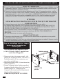
IF YOU HAVE ANY PROBLEMS OR QUESTIONS, EMAIL
OR CALL CUSTOMER SERVICE BEFORE YOU RETURN
THIS PRODUCT TO THE STORE WHERE IT WAS PURCHASED.
For Customer Service: email: par[email protected]
in English Call: 866-661-1218
in Spanish Call: 866-661-1218
in French Call: 866-374-9203
ATENCIÓN
SI TIENE ALGÚN PROBLEMA O PREGUNTAS,
ENVÍE UN MENSAJE DE CORREO ELECTRÓNICO O LLAME AL SERVICIO
DE ATENCIÓN AL CLIENTE ANTES DE DEVOLVER
ESTE PRODUCTO A LA TIENDA EN LA QUE LO COMPRÓ.
Servicio de atención al cliente: Correo electrónico: par[email protected]
Línea para llamadas en inglés: 866-661-1218
Línea para llamadas en español: 866-661-1218
Línea para llamadas en francés: 866-374-9203
STOP STOP
PARE PARE
ATTENTION
SI VOUS AVEZ DES PROBLÈMES OU QUESTIONS,
ENVOYEZ UN COURRIEL AU SERVICE À LA CLIENTÈLE OU APPELEZ LE
SERVICE À LA CLIENTÈLE AVANT DE RETOURNER
CE PRODUIT OÙ VOUS L’AVEZ ACHETÉ.
Pour le service à la clientèle : courriel : par[email protected]
pour le service en anglais, composez le 866-661-1218
pour le service en espagnol, composez le 866-661-1218
pour le service en français, composez le 866-374-9203
ARRÊT ARRÊT
INSTRUCTION MANUAL ENCLOSED
MANUEL D’INSTRUCTION À L’INTÉRIEUR
MANUAL DE INSTRUCCIONES ADJUNTO
INSTRUCTION MANUAL ENCLOSED
MANUEL D’INSTRUCTION À L’INTÉRIEUR
MANUAL DE INSTRUCCIONES ADJUNTO

E-1
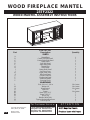
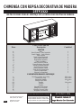
WOOD FIREPLACE MANTEL
23TF2322
WOOD MANTEL ASSEMBLY INSTRUCTIONS
PARTS LIST
Description
PARTS
Hearth/Base
Center Left Side Panel
Center Right Side Panel
Center Shelf
Left Side Panel
Right Side Panel
Mantel/Top
Wood Shelf
Center Back Panel
Left Front Door
Right Front Door
Side Back Panel
Center Front Bar
Positioning Panel
Stabilizer Frame
Securing Block
HARDWARE
Bolt 1/4 in. x 1-1/4 in.
Washer 1/4
Wood Dowel
Shelf Pin
Screw
Screw 5/32”*1/2”
Screw 5/32”*1”
Door Clip
Handle (With Bolt)
Tipping Restraint Hardware
Touch Up Pen
Part
A
B
C
D
E
F
G
H
I
J
K
P
S
T
U
Y
L
M
N
O
Q1
Q2
Q3
R
V
W
Z
Quantity
1
1
1
1
1
1
1
1
1
1
1
1
1
1
1
1
28+1 extra
28+1 extra
26+1 extra
4
24+1 extra
2
7
1
2
2
1
ALSO Requires-Electric
ALSO Requires-Electric
Fireplace Insert with Heater
Fireplace Insert with Heater
E-mail: [email protected]
In English call: 866-661-1218
In French call: 866-374-9203
In Spanish call: 866-661-1218
ATTENTION
For Customer Service:
Twin-Star International, Inc.
Delray Beach, FL 33445
Made in China
Printed in China

E-2
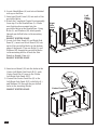
For a complete tight fi t every bolt
should have a fl at washer.
All panels are labeled Left and Right as
viewed from the front of unit.
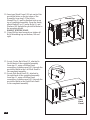
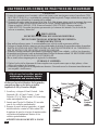
1. Locate the Center Left Side Panel (B), Center
Right Side Panel (C), Center Shelf (D), and
set out face down on a scratch-free surface.
2. Insert one Wood Dowel (N) into each of the
pre-drilled holes.
3. Push the Center Left Side Panel and Center
Right Side Panel snug to the Center Shelf (D).
Make sure the Wood Dowels are seated in
the pre-drilled holes.
HAND TIGHTEN ONLY.
Center
Left
Side
Panel
Center
Right
Side
Panel
Center Shelf
L
M
NN
N
B
C
D
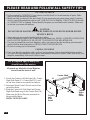
PLEASE READ AND FOLLOW ALL SAFETY TIPS
GETTING STARTED
1. Before assembly, CAREFULLY use scissors or utility knife to cut and unwrap all parts. Make
sure you do not discard the hardware.
2. Make sure that you have all the parts listed. If you are missing any parts please email Customer
Service: [email protected] or call 1-866-661-1218 in English, 1-866-374-9203 in French
or 1-866-661-1218 in Spanish. Please identify the parts you need and model number. Make sure
to include your name and address.
CAUTION:
DO NOT MOVE MANTEL OR INSERT WHILE PLUGGED INTO POWER SUPPLY.
HELPFUL HINTS
• Some steps are more easily handled with two adults.
• Attach the fi replace insert to the completed wood mantel last. INSTALL INSERT IN FROM THE
BACK OF THE FIREPLACE SO AS NOT TO SCRATCH THE HEARTH/BASE.
• Use care in assembling your new fi replace, take your time and use the hardware provided and a
quality Phillips head screwdriver. NEVER OVER TIGHTEN BOLTS.
• Do not sit on any part of the mantel.
CARE & CLEANING
1. Dust your fi replace regularly with a soft non-lint producing cloth or household dusting product.
2. You can clean your fi replace with a gentle non-abrasive household cleaner. Make sure to dry your
fi replace immediately with a soft cloth or towel.

E-3
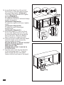
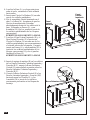
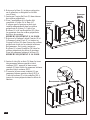
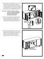
8. Insert wood dowel (N) into the holes in the
Center Left/Right Side Panel (B/C), push
Center Front Bar (S) snug to the Center
Left/Right Side Panel (B/C).
9. Connect the Center Front Bar (S) to the
Left/Right Side Panel (E/F) with Bolts (L)
and Washers (M) through the pre-drilled
holes in the mounting blocks.
HAND TIGHTEN ONLY.
4. Locate Hearth/Base (A) and set out fi nished
side up on the fl oor.
5. Insert one Wood Dowel (N) into each of the
pre-drilled holes.
6. Attach the Completed Center Front assembly
from step 3 to the Hearth/Base (A). Make
sure that dowels are seated into the
pre-drilled holes in the Hearth/Base. Using
Bolts (L) and Washers (M) attach panels
through pre-drilled holes in the mounting
blocks.
HAND TIGHTEN ONLY.
7. Locate Left Side Panel (E) and Right Side
Panel (F), insert one Wood Dowel (N) into
each of the pre-drilled holes on the bottom
edge of the panels. Then use Bolts (L) and
Washers (M) through the pre-drilled holes
in the mounting blocks. Attach the Side
Panels to Hearth / Base (A).
HAND TIGHTEN ONLY.
Left
Side
Panel
Right
Side
Panel
Hearth/Base
Center Front Bar
LL
L
NN
N
N
N
N
A
S
N
N
N
MM
M
E
F

E-4
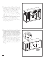
I
Q1
Q1
Center
Back
Panel
P
Mantel/Top
G
LM
Side
Back
Panel
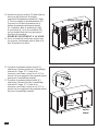
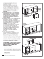
10. Insert one Wood Dowel (N) into each of the
pre-drilled holes on the top edges of the
Assembly from step 9. Then locate
Mantel/Top (G) and lay fi nished side up on
top of completed assembly. From the inside,
attach Mantel/Top (G) using Bolts (L) and
Washers (M) through the pre-drilled holes in
the mounting blocks.
HAND TIGHTEN ONLY.
11. Using Phillips head screwdriver tighten all
Bolts alternating top and bottom, left and
right.
12. Locate Center Back Panel (I), attached to
the left back of the completed assembly
from step 11, using a Phillips Head
screwdriver, tighten screws (Q1) through the
pre-drilled holes in the Left Back Panel to
the completed assembly.
13. Locate Side Back Panel (P), attached to
the right back of the completed assembly
from step 11, using a Phillips Head
screwdriver, tighten screws (Q1) through the
pre-drilled holes in the Right Back Panel
to the completed assembly.
NN
N
N

E-5
ab
c
123
Left
Front
Door
Right
Front
Door
Handle
(with bolt)
K
V
J
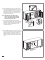
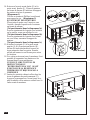
14. Locate Right Front Door (K) and Left
Front Door (J). Slide door hinge keyhole
into panel hinge bracket. (Diagram 1)
Use Phillips Head Screwdriver to tighten
screws. (Diagram 2)
TO ADJUST HINGES
To adjust door forward or backward change
keyhole slot position.
(As Shown In Diagram 3a)
To adjust door right or left loosen / tighten
screw.
(As Shown In Diagram 3b)
To adjust door up or down adjust
bracket height.
(As Shown In Diagram 3c).
15. Attach the Handle (V) to the Left Front
Door (J) and Right Front Door (K), use
the bolts attached through the pre-drilled
holes in the doors. Then use a Phillips
Head Screwdriver to tighten the bolts.
16. There are levelers located under the mantel
which the height can be increased by
twisting counter-clockwise.
PLEASE READ ALL “WINE COOLER”
INSTRUCTIONS PRIOR TO
INSTALLING THE
THERMOELECTRIC COOLER IN
YOUR MANTEL.
17. Insert the wine cooler feet into the holes
of the Positioning Panel (T). Push the
panel forward until the cooler makes
contact with the front frame of the mantel.
Positioning
Panel
T
Leveler

E-6
O
H
R
Q2
Q3
T
U
Q3
Q3
Shelf Pin
Stabilizer
Frame
Positioning
Panel
Door
Clip
Wood
Shelf
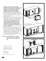
18. Open the Right Front Door (K) and cooler
door, connect the Right Front Door (K) to the
cooler door with the Door Clip (R). Close
door and adjust the wine cooler forwards or
backwards to insure a smooth operation of
the door with a tight seal.
Note: Installing the clip with the door
open at a 45 degree angle will help
insure a smooth operation through
the full motion of the door.
19. Choose desired height of Shelf (H) and
place the four Shelf Pin (O) into same height
shelf holes inside side panels. Insert Wood
Shelf (H), allow Wood Shelf (H) to rest
on the Shelf Pin (O).
20. Insert Stabilizer Frame (U) once the cooler is
in the correct position. Fasten the positioning
panel with wood screws (Q3). Wedge the
Stabilizer Frame (U) between the top of the
cooler and mantel. Fasten with wood screws
(Q3).

E-7
PLEASE READ ALL “ELECTRIC
FIREPLACE INSERT” INSTRUCTIONS
PRIOR TO INSTALLING ELECTRIC
INSERT IN YOUR COMPLETED
FIREPLACE MANTEL. INSTALL
THE INSERT IN YOUR FIREPLACE
21. Lift insert carefully into the back of the unit
and center in the insert opening. Do not drag
insert across Hearth/Base (A) as it may
scratch your unit.
22. Insert Wood Dowel (N) into the holes in the
Hearth/Base (A). Attach Securing Block (Y)
to hold insert from back. Using the Bolts (L)
and Washers (M) through pre-drilled holes.
MOVE YOUR COMPLETED UNIT
ONLY SHORT DISTANCES. MOVE
COMPLETED UNIT WITH GREAT
CARE. IT TAKES TWO PEOPLE TO
MOVE COMPLETED UNIT INTO ITS
FINAL POSITION.
23. We have included two Tipping Restraints for
this unit. You must install this hardware to
prevent accidents or injuries. When properly
installed, this restraint can provide protection
against unexpected tipping of the Unit due to
small tremors, bumps or climbing. We
strongly recommend mounting this hardware
to a wall stud and your Unit.
Warning: You must install the Tipping
Restraint Hardware to help pre
vent accidents or damage to the
unit.
Twin-Star International, Inc.
Delray Beach, FL 33445
In English: 1-866-661-1218
In French: 1-866-374-9203
In Spanish: 1-866-661-1218
Model# 23TF2322
Made in China
Printed in China
© 2011, Twin-Star International, Inc.
Electric
Fireplace Insert
Completed Unit
Securing
Block
Y
Cabinet
Wall Stud
L
M
Wall
Install
Insert
From
Back

E-1S-1
23TF2322
CHIMENEA CON REPISA DECORATIVA DE MADERA
INSTRUCCIONES PARA EL MONTAJE DE LA REPISA DECORATIVA DE MADERA
LISTA DE PIEZAS
Descripción
PIEZAS
Base
Panel Central – Lado Izquierdo
Panel Central – Lado Derecho
Tabla Central
Panel Lateral Izquierdo
Panel Lateral Derecho
Repisa/Parte Superior
Tabla De Madera
Panel Posterior Central
Puerta Delantera Izquierda
Puerta Delantera Derecha
Panel Posterior Lateral
Barra Delantera Central
Panel de Posicionamiento
Marco Estabilizador
Bloque De Seguridad
ELEMENTOS PARA EL MONTAJE
Tornillo 1/4 Pulg. X 1/4 Pulg.
Arandela ¼ Pulg.
Espiga De Madera
Clavijas Para Tabla
Tornillo
Tornillo
Tornillo
Sujetador de la Puerta
Mango (Con Tornillo)
Herrajes Contra Caídas
Bolígrafo Para Retocar
Necesitará, Además, El
Necesitará, Además, El
Hogar Eléctrico Con Calentador
Hogar Eléctrico Con Calentador
Correo electrónico: [email protected]
Línea para llamadas en inglés: 866-661-1218
Línea para llamadas en francés: 866-374-9203
Línea para llamadas en español: 866-661-1218
ATENCIÓN
Servicio de atención al cliente:
Twin-Star International, Inc.
Delray Beach, FL 33445
Fabricado en China
Impreso en China
Pieza
A
B
C
D
E
F
G
H
I
J
K
P
S
T
U
Y
L
M
N
O
Q1
Q2
Q3
R
V
W
Z
Cantidad
1
1
1
1
1
1
1
1
1
1
1
1
1
1
1
1
28+1 extra
28+1 extra
26+1 extra
4
24+1 extra
2
7
1
2
2
1

E-2S-2
L
M
NN
N
B
C
D
A fi n de que los tornillos queden
debidamente ajustados, deberá
colocarles una arandela plana.
Si observa la parte delantera de los paneles,
comprobará que en los lados se indica
Izquierda (Left) y Derecha (Right).
LEA TODOS LOS CONSEJOS PRÁCTICOS DE SEGURIDAD
COMIENZO
1. Antes de comenzar con el montaje, utilice las tijeras o una navaja para cortar el envoltorio CON
MUCHO CUIDADO y, a continuación, extraiga todas las piezas. Tenga cuidado de no arrojar los
elementos que utilizará en el montaje de la unidad.
2. Controle que estén todas las piezas de la lista. Si le falta alguna pieza, envíe un mensaje de correo
electrónico o llame a Servicios de atención al cliente: [email protected], o llame al:
(línea en inglés)1-866-661-1218; (línea en francés)1-866-374-9203; (línea en español)
1-866-661-1218. Describa las piezas que necesita y el número del modelo. No se olvide de
colocar su nombre y dirección.
PRECAUCIÓN:
NO MUEVA LA REPISA NI EL HOGAR MIENTRAS
ESTÁN CONECTADOS AL SUMINISTRO DE ENERGÍA.
CONSEJOS PRÁCTICOS
• Para realizar algunos pasos, le recomendamos que solicite ayuda a personas adultas.
• Coloque el hogar eléctrico una vez que haya terminado de montar la repisa decorativa de madera.
INSTALE EL HOGAR ELÉCTRICO DESDE LA PARTE POSTERIOR DE LA CHIMENEA A
FIN DE EVITAR QUE SE DAÑE LA BASE DEL HOGAR.
• Tómese el tiempo necesario para armar la chimenea, hágalo con cuidado, y utilice los elementos
de montaje provistos así como un destornillador Phillips de buena calidad. LE RECOMENDAMOS
QUE NO AJUSTE DEMASIADO LOS TORNILLOS.
• No se siente sobre ninguna parte la repisa de la chimenea.
CUIDADO Y LIMPIEZA
1. Quite el polvo de la chimenea de forma regular con un paño suave que no deje pelusa, o bien
utilice un producto de limpieza.
2. Asimismo, puede aplicar un limpiador no abrasivo. Recuerde secar la chimenea inmediatamente
con un paño o toalla suave.
1. Localice y coloque el Panel Central – Lado
Izquierdo (B), el Panel Central – Lado
Derecho (C) y la Tabla central (D) boca abajo,
sobre una superfi cie lisa.
2. Inserte una Clavija De Madera (N) en cada
uno de los orifi cios pretaladrados.
3. Empuje el panel interior izquierdo y el panel
interior derecho contra la Tabla central (D).
Asegúrese de que las clavijas de madera estén
colocadas adecuadamente dentro de los
orifi cios pretaladrados.
APRIETELOS SOLAMENTE A MANO
Tabla Central
Panel
Central-
Lado
Izquierdo
Panel
Central-
Lado
Derecho

E-3S-3
Barra Delantera Central
LL
L
NN
N
N
N
NA
S
N
N
N
MM
M
E
F
Base
4. Localice la Base (A) y coloque esta pieza
sobre el suelo, orientando el lado acabado
hacia arriba.
5. Inserte una Clavija De Madera (N) en cada
uno de los orifi cios pretaladros.
6. Fije el ensamblaje frontal terminado en el
paso 3 a la Base (A). Asegúrese de que las
clavijas de madera estén colocadas
adecuadamente dentro de los orifi cios de la
base. Utilizando un Pernos (L) y una
Arandelas (M), fi je los paneles a través de
los orifi cios pretaladrados de los bloques
para montaje.
APRIETELOS SOLAMENTE A MANO.
7. Localice el Panel Lateral Izquierdo (E) y el
Panel Lateral Derecho (F) e inserte una
Clavija De Madera (N) en cada uno de los
orifi cios pretaladrados, que se encuentran en
el reborde inferior de los paneles. Después,
inserte un Pernos (L) y una Arandelas (M) a
través de los orifi cios pretaladrados de los
bloques para montaje. Fije los el paneles
laterales a la Base (A).
APRIETELOS SOLAMENTE A MANO
8. Inserte la espiga de madera (N) en los orifi cios
de los Paneles Laterales Centrales Izquierdo y
Derecho (B/C), empuje la Barra Delantera
Central (S) para encajarla a presión sobre los
Paneles Laterales Centrales Izquierdo y
Derecho (B/C).
9. Conecte la Barra Delantera Central (S) a los
Paneles Laterales Izquierdo y Derecho (E/F)
haciendo pasar los Tornillos (L) y las
Arandelas (M) a través de los orifi cios
previamente perforados en los bloques de
montaje.
Panel
Lateral
Izquierdo
Panel
Lateral
Derecho

E-4S-4
I
Q1
Q1
P
G
LM
Repisa/Parte Superior
NN
N
N
10. Inserte una Espiga De Madera (N) en cada
uno de los orifi cios previamente perforados
del borde superior del Conjunto que armó en
el paso 9. Luego, tome la Repisa/Parte
Superior (G) y colóquela, con el lado
acabado hacia arrinba, sobre el conjunto
armado. Desde el interior, ajuste la Repisa
colocando un Tornillos (L) y una Arandelas
(M) en los orifi cios previamente perforados
de los bloques de montaje.
APRIETELOS SOLAMENTE A MANO.
11. Utilizando un destornillador Phillips
(cruciforme), apriete todos los pernos,
alternando entre la parte superior e inferior,
la izquierda y la derecha.
12. Busque el Panel Posterior Central (I), sujeto
a la parte posterior izquierda del conjunto
armado en el paso 11, y ajústelo al conjunto
armado atornillando los tornillos (Q1) en los
orifi cios previamente perforados del Panel
Posterior Izquierdo con un destornillador
Phillips.
13. Busque el Panel Posterior Lateral (P), sujeto
a la parte posterior derecha del conjunto
armado en el paso 11, y ajústelo al conjunto
armado atornillando los tornillos (Q1) en los
orifi cios previamente perforados del Panel
Posterior Derecho con un destornillador
Phillips.
Panel
Posterior
Lateral
Panel Posterior Central

E-5S-5
ab
c
123
Puerta
Delantera
Derecha
Puerta
Delantera
Izquierda
K
V
J
Panel de
Posicionamiento
T
14. Localice la Puerta Delantera Derecha (K)
y la Puerta Delantera Izquierda (J).
Deslice la ranura en forma de cerradura
de la bisagra situado sobre el panel.
(Diagrama 1)
Utilice un destornillador Phillips
(cruciforme), para apretar los tornillos.
(Diagrama 2)
PARA AJUSTAR LAS BISAGRAS
Para ajustar la puerta hacia adelante o
hacia detrás, cambie la posición de la
ranura en forma de cerradura.
(como se muestra en el diagrama 3a)
Para ajustar la puerta hacia la derecha o
hacia la izquierda, apriete o destornille el
tornillo.
(Como se muestra en el diagrama 3b)
Para ajustar la puerta hacia arriba o hacia
abajo, ajuste la altura del soporte de
bisagra.
(Como se muestra en el diagrama 3c)
15. Fije el Mango (V) a la Puerta Delantera
Izquierda (J) y a la Puerta Delantera Derecha
(K), utilice los tornillos que atraviesan los
orifi cios previamente perforados en las
puertas. Luego, utilice un destornillador
Phillips para ajustar los tornillos.
16. Hay niveladores debajo del madera. Para
aumentar su altura, se debe girarlos en
sentido contrario a las agujas del reloj.
POR FAVOR LEA TODAS LAS
INSTRUCCIONES PARA EL
“ENFRIADOR DE VINO”. PRIORIDAD
PARA INSTALAR EL TERMO
ELÉCTRICO. ENFRIADOR EN SU
MANTEL.
17. Inserte los pies de la heladera de vinos en los
orifi cios del Panel de Posicionamiento (T).
Empuje el panel hacia adelante hasta que
la heladera entre en contacto con el marco
delantero de la repisa.
Mango
(con Tornillo)
Nivelador

E-6S-6
O
H
R
Q2
Q3
T
U
Q3
Q3
Marco
Estabilizador
Panel de
Posicionamiento
Sujetador
de la Puerta
18. Abra la Puerta Delantera Derecha (K) y la
puerta de la heladera, conecte la Puerta
Delantera Derecha (K) con la puerta de la
heladera utilizando el Sujetador de la Puerta
(R). Cierre la puerta y ajuste la posición de
la heladera de vinos hacia adelante o hacia
atrás para garantizar la perfecta operación de
la puerta con un sellado hermético.
Nota: Instalando el sujetador con la puerta
abierta en un ángulo de 45 grados,
permitirá garantizar una perfecta
operación a lo largo de toda la
amplitud de movimiento de la puerta.
19. Elija la altura deseada para la instalación de
la Tabla (H) e inserte las cuatro clavijas en
los orifi cios de misma altura, dentro de los
paneles laterales. Inserte la Tabla (H) y
asegúrese de que la tabla descanse sobre las
Clavijas Para Tabla (O).
20. Inserte el Marco Estabilizador (U) una vez
que la heladera se encuentre en la posición
correcta. Ajuste el panel de posicionamiento
con tornillos para madera (Q3). Acuñe el
Marco Estabilizador (U) entre la parte
superior de la heladera y la repisa. Ajuste con
tornillos para madera (Q3).
Tabla De
Madera
Clavijas Para Tabla

E-7S-7
Unidad
Terminada
Bloque De
Seguridad
Hogar Eléctrico
Para Chimenea
Instalar El
Hogar Desde
La Parte
Posterior
Twin-Star International, Inc.
Delray Beach, FL 33445
Línea para llamadas en inglés: 1-866-661-1218
Línea para llamadas en francés: 1-866-374-9203
Línea para llamadas en español: 1-866-661-1218
Modelo N° 23TF2322
Fabricado en China
Impreso en China
© 2011, Twin-Star International, Inc.
Gabinete
Taco De Pared
Pared
Y
L
M
LEA ATENTAMENTE TODAS LAS
INSTRUCCIONES DEL “HOGAR
ELÉCTRICO” ANTES DE SU
INSTALACIÓN EN LA CHIMENEA
DECORATIVA. UBIQUE EL
HOGAR ELÉCTRICO EN LA
POSICIÓN DEFINITIVA DENTRO
DE LA CHIMENEA.
21. Levante el hogar cuidadosamente, colóquelo
en la parte posterior de la unidad y céntrelo
en la abertura de la chimenea. No empuje el
hogar desde su Base dado que la unidad se
puede dañar.
22. Inserte una Espiga de Madera (N) en los
orifi cios de la Base del Hogar (A). Sujete el
Bloque de Seguridad (Y) con un Perno (L) y
una Arandela (M) por los orifi cios
previamente perforados para sostener el
hogar desde atrás.
MUEVA LA UNIDAD COMPLETA
SÓLO EN DISTANCIAS CORTAS.
MUEVA LA UNIDAD COMPLETA
CON MUCHO CUIDADO. SE
NECESITAN DOS PERSONAS PARA
DESPLAZAR LA UNIDAD
COMPLETA AL LUGAR
DEFINITIVO QUE VA A OCUPAR.
23. Hemos incluido dos Herrajes contra Caídas
para esta unidad. Debe instalar estos herrajes
para evitar accidentes o lesiones. Cuando se
los instala correctamente, brindan
protección contra la caída inesperada del
gabinete debido a temblores leves, o a que
alguien choque la unidad o se trepe a ella.
Recomendamos montar estos herrajes a un
taco de pared y a la Unidad.
Advertencia: Debe instalar el Herraje
contra Caídas para evitar accidentes o que
se dañe la unidad.

F-1
MANTEAU DE FOYER EN BOIS
23TF2322
INSTRUCTIONS D’ASSEMBLAGE POUR LE MANTEAU EN BOIS
Exige aussi -foyer
Exige aussi -foyer
encastrable électrique avec
encastrable électrique avec
Chauffage
Chauffage
courriel : [email protected]
pour le service en anglais, composez le 866-661-1218
pour le service en français, composez le 866-374-9203
pour le service en espagnol, composez le 866-661-1218
ATTENTION
Pour le service à la clientèle :
Twin-Star International, Inc.
Delray Beach, FL 33445
Fabriqué en Chine
Imprimé en Chine
LISTE DES PIÈCES
Description
PIÈCES
Base
Panneau central - côté gauche
Panneau central - côté droit
Tablette centrale
Panneau latéral gauche
Panneau latéral droit
Manteau/dessus
Tablette en bois
Panneau arrière central
Porte avant gauche
Porte avant droite
Panneau arrière latéral
Barre avant centrale
Panneau de positionnement
Cadre stabilisateur
Bloc de retenue
QUINCAILLERIE
Boulon 1/4 Po x 1-1/4 Po
Rondells
Goujon en bois
Cheville pour tablette
Vis
Vis
Vis
Clip de porte
Poignée (arec boulon)
Quincaillerie d’arrimage anti basculement
Crayon pour retouches
Pièce
A
B
C
D
E
F
G
H
I
J
K
P
S
T
U
Y
L
M
N
O
Q1
Q2
Q3
R
V
W
Z
Quantité
1
1
1
1
1
1
1
1
1
1
1
1
1
1
1
1
28+1 extra
28+1 extra
26+1 extra
4
24+1 extra
2
7
1
2
2
1

F-2
Panneau
central - côté
gauche
Panneau
central - côté
droit
Tablette centrale
L
M
NN
N
B
C
D
Pour un assemblage sans jeu, chaque
boulon devrait comporter une
rondelle plate.
Tous les panneaux sont étiquetés Gauche
(« Left ») et Droit (« Right ») à partir d’une
vue de face de l’appareil.
VEUILLEZ LIRE ET SUIVRE TOUS LES CONSEILS DE SÉCURITÉ
AVANT DE COMMENCER
1. Avant l’installation, utilisez des ciseaux ou un couteau universel pour couper et déballer tous les
composants. Faites ATTENTION de ne pas endommager le manteau. Assurez-vous de ne pas
jeter la quincaillerie d’installation incluse.
2. Assurez-vous d’avoir toutes les pièces indiquées sur la liste. S’il manque des pièces, veuillez
envoyer un courriel au service à la clientèle à l’adresse [email protected] ou composez
les numéros suivants : pour le service en anglais : 1-866-661-1218; pour le service en français :
1-866-374-9203 ou pour le service en espagnol-866-661-1218. Veuillez indiquer les pièces
manquantes ainsi que le numéro de modèle. Assurez-vous d’inclure vos nom et adresse.
ATTENTION
NE PAS DÉPLACER LE MANTEAU OU LE FOYER TANT QU’IL EST BRANCHÉ.
CONSEILS UTILES
• Certaines étapes seront plus faciles à réaliser avec l’aide d’un autre adulte.
• La dernière étape consistera à lier le manteau entièrement monté au foyer. INSTALLEZ LE
FOYER ENCASTRABLE EN LE DÉPOSANT PAR L’ARRIÈRE DU MANTEAU POUR
ÉVITER D’ÉGRATIGNER L’ÂTRE/BASE DU MANTEAU.
• Faites attention lorsque vous assemblez le foyer et le manteau. Prenez votre temps et utilisez la
quincaillerie fournie, ainsi qu’un tournevis cruciforme. NE PAS TROP SERRER LES
BOULONS.
• Ne vous asseyez pas sur aucune partie du manteau.
SOINS ET NETTOYAGE
1. Époussetez régulièrement votre FOYER avec un chiffon doux non pelucheux ou un produit
do mestique pour l’époussetage.
2. Vous pouvez nettoyer le foyer avec un nettoyant domestique doux non abrasif. Assurez-vous de
l’essuyer immédiatement avec un linge doux ou une serviette.
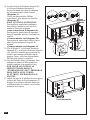
1. Retrouver et placer le panneau central - côté
gauche (B), le panneau central - côté droit (C),
la tablette centrale (D) face contre terre, sur
une surface antiérafl ures.
2. Insérer un goujon en bois (N) dans chacun des
orifi ces préperforés.
3. Pousser le panneau latéral intérieur gauche et
le panneau latéral intérieur droit, tout contre la
tablette centrale (D). S’assurer que les
Goujons En Bois sont installés adéquatement
dans les orifi ces préperforés.
SERRER UNIQUEMENT À LA MAIN.

F-3
Barre avant centrale
LL
L
NN
N
N
N
N
A
S
N
N
N
MM
M
E
F
Base
4. Retrouver la Base (A) et placer cette pièce
sur le plancher, en dirigeant le côté fi ni
vers le haut.
5. Insérer un Goujon En Bois (N) dans chacun
des orifi ces préperforés.
6. Fixer l’assemblage de la façade déjà
complétée à l’étape 3 à la Base (A).
S’assurer que les goujons en bois sont
installés adéquatement dans les orifi ces
préperforés de la base. À l’aide d’un
Boulons (L) et d’une Rondelles (M), fi xer
les panneaux dans les orifi ces préperforés
des blocs de montage.
SERRER UNIQUEMENT À LA MAIN.
7. Retrouver le Panneau Latéral Gauche (E) et
le Panneau Latéral Droit (F) et insérer un
Goujon En Bois (N) dans chacun des orifi ces
préperforés situés sur les rebords inférieurs
des panneaux. Par la suite, insérer un
Boulons (L) et une Rondelles (M) dans les
orifi ces préperforés des blocs de montage.
Fixer les panneaux latéraux à la Base (A).
SERRER UNIQUEMENT À LA MAIN.
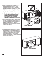
8. Insérer la cheville en bois (N) dans les trous
des panneaux latéraux gauche et droit
centraux (B/C), appuyer la barre avant
centrale (S) bien contre les panneaux latéraux
gauche et droit centraux (B/C).
9. Connecter la barre avant centrale (S) aux
panneaux latéraux gauche et droit (E/F) à
l’aide de boulons (L) et de rondelles (M) à
travers les trous prépercés dans les blocs de
fi xation.
Panneau
latéral
gauche
Panneau
latéral
droit

F-4
I
Q1
Q1
Panneau
arrière
central
P
G
LM
Panneau
arrière
latéral
NN
N
N
Manteau/Dessus
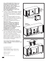
12. Localiser le panneau arrière central (I),
attaché sur l’arrière gauche de l’assemblage
terminé de l’étape 11, à l’aide d’un
tournevis cruciforme, serrer les vis (Q1) à
travers les trous prépercés du panneau arrière
gauche sur l’assemblage terminé.
13. Localiser le panneau arrière latéral (P),
attaché sur l’arrière droit de l’assemblage
terminé de l’étape 11, à l’aide d’un
tournevis cruciforme, serrer les vis (Q1) à
travers les trous prépercés du panneau arrière
droit sur l’assemblage terminé.
10. Insérez un goujon en bois (N) dans chacun
des trous pré-percés de la bordure
supérieure du panneau assemblé à l’étape
9. Trouvez ensuite le manteau/dessue (G).
Déposez le côté fi ni du manteau sur le
dessus du panneau entièrement monté.
De l’intérieur, fi xez le manteau à l’aide
d’un boulons (L) et d’une rondelles (M),
en les insérant dans les trous pré-percés
des blocs de montage.
SERRER UNIQUEMENT À LA MAIN.
11. Avec un tournevis cruciforme, serrez tous
les goujons, en alternant entre le haut et le
bas, la gauche et la droite.

F-5
ab
c
123
Porte
avant
gauche
Porte
avant
droite
Poignée
(arec boulon)
K
V
J
Panneau de
positionnement
T
14. Retrouver la porte avant droite (K) et la
porte avant gauche (J). Glisser la penture
en forme de serrure à l’intérieur du support
de penture situé sur le panneau.
(Diagramme 1)
Utiliser un tournevis Phillips (cruciforme)
pour serrer les vis. (Diagramme 2)
AJUSTEMENT DES PENTURES
Pour ajuster la porte vers l’avant ou vers
l’arrière, changer la position de la rainure
en forme de serrure.
(Tel que démontré dans le diagramme 3a)
Pour un ajustement de la porte vers la droite
ou la gauche, serrer ou relâcher les vis.
(Tel que démontré dans le diagramme 3b)
Pour un ajustement de la porte vers le haut
ou vers le bas, remonter le support de
penture.
(Tel que démontré dans le diagramme 3c)
15. Attacher la poignée (V) à la porte avant
gauche (J) et à la porte avant droite (K),
utiliser les boulons attachés à travers les
trous prépercés dans les portes. Ensuite,
utiliser un tournevis cruciforme pour serrer
les boulons.
16. Des vérins se trouvent sous le manteau; il est
possible d’augmenter leur hauteur en les
tournant dans le sens antihoraire.
VEUILLEZ LIRE TOUTES LES
INSTRUCTIONS DU
“REFRIGIRATEUR A VIN” AVANT
D’INSTALLER LA RESISTANCE
THERMOELECTRIQUE DANS LA
CHEMINEE
17. Insérer les pieds du cabinet-cellier dans les
trous du panneau de positionnement (T).
Appuyer le panneau vers l’avant jusqu’à ce
que le cabinet-cellier entre en contact avec le
cadre avant du manteau.
Vérin
La page est en cours de chargement...
La page est en cours de chargement...
-
 1
1
-
 2
2
-
 3
3
-
 4
4
-
 5
5
-
 6
6
-
 7
7
-
 8
8
-
 9
9
-
 10
10
-
 11
11
-
 12
12
-
 13
13
-
 14
14
-
 15
15
-
 16
16
-
 17
17
-
 18
18
-
 19
19
-
 20
20
-
 21
21
-
 22
22


Chimney Free 23TF2322-C232 Mode d'emploi
- Taper
- Mode d'emploi
dans d''autres langues
Autres documents
-
 Hampton Bay 28MM764-C253 Mode d'emploi
-
Twin-Star International 23MM378 Manuel utilisateur
-
Classic Flame 71388 Guide d'installation
-
-
-
-
-
-
Twin-Star International 23DM537 Assembly Instructions Manual
-
Suncast CC100 Mode d'emploi
