Weller WSD 151 Operating Instructions Manual
- Taper
- Operating Instructions Manual

WSD 151
Betriebsanleitung - Mode d’emploi - Gebruiksaanwijzing - Istruzioni per l’uso - Operating
Instructions - Instruktionsbok - Manual de uso - Betjeningsvejledning - Manual do utilizador -
Käyttöohjeet - √‰ËÁ›Â˜ §ÂÈÙÔ˘ÚÁ›·˜ - Kullan∂m k∂lavuzu -
Návod k pouÏití - Instrukcja obs∏ugi -
Üzemeltetési utasítás - Návod na pouÏívanie - Navodila za uporabo - Kasutusjuhend -
Naudojimo instrukcija - Lieto‰anas instrukcija

D
F
NL
I
GB
S
E
FIN
P
DK
Inhaltsverzeichnis Seite
1. Achtung! 1
2. Beschreibung 1
Technische Daten 1
3. Inbetriebnahme 2
4. Potentialausgleich 2
5. Arbeitshinweise 2
6. Zubehör 3
7. Lieferumfang 3
Table des matières Page
1. Attention! 4
2. Description 4
Caractéristiques techniques 4
3. Mise en service 5
4. Equilibrage de potentiel 5
5. Instructions d'emploi 5
6. Accessoires 6
7. Eléments compris dans la livraison 6
Inhoud Pagina
1. Attentie! 7
2. Beschrijving 7
Technische gegevens 7
3. Ingebruikname 8
4. Potentiaal vereffening 8
5. Werkaanwijzingen 8
6. Toebehoren 9
7. Leveromvang 9
Indice Pagina
1. Attenzione! 10
2. Descrizione 10
Dati tecnici 10
3. Messa in esercizio 11
4. Equalizzazione dei potenziali 11
5. Indicazioni operative 12
6. Accessori 12
7. Volume di fornitura 12
Table of contents Page
1. Caution! 13
2. Description 13
Technical data 13
3. Starting 14
4. Equipotential bonding 14
5. Instruction for use 14
6. Accessories 15
7. Scope of supply 15
Innehållsförteckning Sidan
1. Observera! 16
2. Beskrivning 16
Tekniska data 16
3. Driftstart 17
4. Potentialutjämning 17
5. Arbetsanvisningar 17
6. Tillbehör 18
7. Leveransomfång 18
Indice Página
1. Atención! 19
2. Descripción 19
Datos técnicos 19
3. Puesta en funcionamiento 20
4. Compensación de potencial 20
5. Indicaciones para el trabajo 20
6. Accesorios 21
7. Volumen de suministro 21
Indholdsfortegnelse Side
1. Forsigtig! 22
2. Beskrivelse 22
Tekniske data 22
3. Idrifttagning 23
4. Potentialudligning 23
5. Arbejdshenvisninger 23
6. Ekstratilbehør 24
7. Leveringsomfang 24
Índice Página
1. Atençao! 25
2. Descrição 25
Dados técnicos 25
3. Colocação em funcionamento 26
4. Ligação equipotencial 26
5. Indicações de trabalho 27
6. Lista de acessórios 27
7. Volume de fornecimento 27
Sisällysluettelo Sivu
1. Huomio! 28
2. Kuvaus 28
Tekniset tiedot 28
3. Käyttöönotto 29
4. Potentiaalintasaus 29
5. Työohjeet 29
6. Lisätarvikkeet 30
7. Toimituksen laajuus 30

SLO
TR
GR
CZ
PL
H
SK
LV
LT
EST
Obsah Strana
1. Upozornenie! 46
2. Popis 46
Technické údaje 46
3. Uvedenie do prevádzky 47
4. Vyrovnanie potenciálov 47
5. Pracovné pokyny 47
6. Príslu‰enstvo 48
7. Rozsah dodávky 48
Vsebina Stran
1. Pozor! 49
2. Tehniãni opis 49
Tehniãni podatki 49
3. Pred uporabo 50
4. Izenaãevanje potenciala 50
5. Navodila za delo 50
6. Pribor 51
7. Obseg dobave 51
Sisukord Lehekülg
1. Tähelepanu! 52
2. Kirjeldus 52
Tehnilised andmed 52
3. Kasutuselevõtmine 53
4. Potentsiaalide ühtlustamine 53
5. Tööjuhised 53
6. Lisavarstus 54
7. Tarne sisu 54
Turinys Puslapis
1. Dòmesio! 55
2. Apra‰ymas 55
Techniniai duomenys 55
3. Pradedant naudoti 56
4. Potencial˜ i‰lyginimas 56
5. Darbo nurodymai 56
6. Papildoma ∞ranga 57
7. Tiekiamas komplektas 57
Satura rÇd¥tÇjs Lappuse
1. Uzman¥bu! 58
2. Apraksts 58
Tehniskie dati 58
3. Nodo‰ana ekspluatÇcijÇ 59
4. PotenciÇlu izl¥dzinljana 59
5. Lieto‰anas norÇd¥jumi 59
6. Piederumu saraksts 60
7. PiegÇdes komplekts 60
¶›Ó·Î·˜ ÂÚȯÔÌ¤ÓˆÓ ™ÂÏ›‰·
1. ¶ÚÔÛÔ¯‹! 31
2. ¶ÂÚÈÁÚ·Ê‹ 31
Δ¯ÓÈο ÛÙÔȯ›· 31
3. ∞Ú¯È΋ ı¤ÛË Û ÏÂÈÙÔ˘ÚÁ›· 32
4. ∂͛ۈÛË ‰˘Ó·ÌÈÎÔ‡ 33
5. √‰ËÁ›Â˜ ÂÚÁ·Û›·˜ 33
6. ™˘ÌÏËڈ̷ÙÈο ÂÍ·ÚÙ‹Ì·Ù· 33
7. ª¤ÁÂıÔ˜ Ù˘ ·Ú¿‰ÔÛ˘ 33
Íçindekiler Sayfa
1. Dikkat! 34
2. Tan∂m 34
Teknik veriler 34
3. Devreye alma 35
4. Potansiyel dengelemesi 35
5. Çal∂μma uyar∂lar∂ 35
6. Aksesuar 36
7. Teslimat kapsam∂ 36
Obsah Strana
1. Pozor! 37
2. Popis 37
Technické údaje 37
3. Uvedení do provozu 38
4. Vyrovnání potenciálÛ 38
5. Pracovní pokyny 38
6. Pfiíslu‰enství 39
7. Rozsah dodávky 39
Spis treÊci Strona
1. Uwaga! 40
2. Opis 40
Dane techniczne 40
3. Uruchomienie 41
4. Wyrównanie potencja∏u 41
5. Wskazówki dot. pracy 42
6. Akcesoria 42
7. Zakres wyposa˝enia 42
Tartalomjegyzék Oldal
1. Vigyázat! 43
2. Leírás 43
Mıszaki adatok 43
3. Üzembevétel 44
4. Potenciálkiegyenlítés 44
5. Útmutató a munkához 44
6. Tartozéklista 45
7. Tartozékok 45


FIN
P
DKE
S
GB
I
NL
F
D
TR
GR
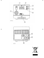
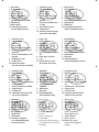
1. Netzschalter
2. Digitalanzeige
3. „UP“ Taste
4. „DOWN“ Taste
5. Optische Regelkontrolle
6. Potentialausgleichbuchse
7. Anschlußbuchse für Lötkolben
8. Netzanschluß
9. Netzsicherung
10. Spannungswahlschalter
(nur umschaltbare Version)
1. Interrupteur secteur
2. Afficheur numérique
3. Touche "Up"
4. Touche "Down"
5. Contrôle visuel du réglage
6. Prise de compensation du
potentiel
7. Prise de raccordement du fer
à souder
8. Raccordement secteur
9. Fusible secteur
10. Sélecteur de tension (unique
ment version commutable)
1. Netschakelaar
2. Digitaaldisplay
3. ”Up” toets
4. ”Down” toets
5. Optische regelcontrole
6. Potentiaalcompensatiebus
7. Aansluitbus voor soldeerapparaat
8. Netaansluiting
9. Netzekering
10. Spanningskeuzeschakelaar
(alleen omschakelbare versie)
1. Interruttore di rete
2. Display digitale
3. Tasto "Up"
4. Tasto "Down"
5. Controllo di regolazione ottico
6. Boccola per compensazione di
potenziale
7. Boccola di collegamento per stilo
brasatore
8. Collegamento a rete
9. Fusibile di rete
10. Selettore di tensione
(solo nella versione commutabile)
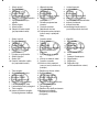
1. Power cable
2. Digital display
3. UP button
4. DOWN button
5. Optical regulator
6. Equipotential bonding bush
7. Connection bush for soldering
iron
8. Power supply connector
9. Fuse
10. Voltage selection switch
(dual-voltage version only)
1. Nätströmbrytare
2. Digitalindikation
3. UP-tangent
4. DOWN-tangent
5. Optisk regleringskontroll
6. Potentialutjämningsbussning
7. Anslutningsbussning till lödkolv
8. Nätanslutning
9. Nätsäkring
10. Spänningsvalbrytare
(endast omkopplingsbar version)
1. Interruptor de red
2. Indicación digital
3. Tecla ”UP”
4. Tecla ”DOWN”
5. Control óptico de regulación
6. Conector hembra para compensa
ción de potencial
7. Conector hembra para soldador
8. Conexión de red
9. Fusible de red
10. Conmutador selector de tensión
(sólo versión conmutable)
1. Netafbryder
2. Digitalvisning
3. “UP”-taste
4. “DOWN”-taste
5. Optisk regulatorkontrol
6. Potentialudligningsbøsning
7. Tilslutningsbøsning til
loddekolbe
8. Nettilslutning
9. Netsikring
10. Spændingsomskifter
(kun omskiftelig version)
1. Interruptor de rede
2. Mostrador digital
3. Tecla "Up"
4. Tecla "Down"
5. Controlo visual da regulação
6. Conector para a ligação equipoten
cial
7. Conector para o ferro de soldar
8. Ligação à rede
9. Fusível de rede
10. Interruptor selector de tensão
(apenas versão comutável)
1. Verkkokytkin
2. Digitaalinen näyttö
3. "UP"-näppäin
4. "DOWN"-näppäin
5. Optinen säätökontrolli
6. Potentiaalintasausliitäntä
7. Kolvin liitäntä
8. Verkkoliitäntä
9. Verkkosulake
10. Jännitteen valintakytkin
(vain vaihtomahdollisuuden
omaavissa laitteissa)
1. ∏ÏÂÎÚÈÎfi˜ ‰È·ÎfiÙ˘
2. æËÊȷ΋ ¤Ó‰ÂÈÍË
3. ¶Ï‹ÎÙÚÔ „UP“
4. ¶Ï‹ÎÙÚÔ „DOWN“
5. √ÙÈÎfi˜ Ú˘ıÌÈÛÙÈÎfi˜ ¤ÏÂÁ¯Ô˜
6. ÀÔ‰Ô¯‹ Â͛ۈÛ˘ ‰˘Ó·ÌÈÎÔ‡
7. ™˘Ó‰ÙÈ΋ ˘Ô‰Ô¯‹ ÁÈ· ÙÔ ¤Ì‚ÔÏÔ
Û˘ÁÎÔÏÏ‹ÛˆÓ
8. ™‡Ó‰ÂÛË ÛÙÔ ËÏÂÎÙÚÈÎfi Ú‡̷
9. ∏ÏÂÎÙÚÈ΋ ·ÛÊ¿ÏÂÈ·
10. ¢È·ÎfiÙ˘ ÂÈÏÔÁ‹˜ ËÏÂÎÙÚÈ΋˜ Ù¿Û˘ (ÌfiÓÔ
ÁÈ· ÙÔÓ Î·Ù·Û΢·ÛÙÈÎfi ÙÚfiÔ Ì ‰˘Ó·ÙfiÙËÙ·
ÌÂÙ·ÚÚ‡ıÌÈÛ˘)
1. Ωebeke μalteri
2. Dijital gösterge
3. "UP" (yukar∂) tuμu
4. "DOWN" (aμaπ∂) tuμu
5. Optik ayar kontrolü
6. Potansiyal dengeleme fiμ
yuvas∂
7. Havya baπlant∂ yuvas∂
8. Ωebeke baπlant∂s∂
9. Ωebeke sigortas∂
10. Gerilim seçme μalteri
(sadece devre deπiμtirmeli
versiyon)

LV
LT
SLO
SK
H
PLCZ
EST
1. Elektr¥bas baro‰anas slïdzis
2. DigitÇlie rÇd¥jumi
3. "UP" (Aug‰up) tausti¿‰
4. "DOWN" (Lejup) tausti¿‰
5. OptiskÇ regulï‰ana
6. PotenciÇlu izl¥dzinljanas bukse
7. LodÇmura pieslïgbukse
8. T¥kla pieslïgums
9. Elektr¥bas t¥kla dro‰¥bas elements
10.Sprieguma pÇrslïdzïjs
(tikai versijai ar mainÇmo
pieslïgumu)
1. SíÈov˘ vypínaã
2. Digitální displej
3. Tlaãítko UP
4. Tlaãítko DOWN
5. Optická kontrola regulace
6. Zdífika pro vyrovnání potenciálu
7. Pfiipojovací zásuvka pro
pájeãku
8. SíÈová pfiípojka
9. SíÈová pojistka
10. Pfiepínaã síÈového napûtí
(jen pfiepínatelná verze)
1. W∏àcznik sieciowy
2. Wskaênik cyfrowy
3. Przycisk UP
4. Przycisk DOWN
5. Optyczna kontrola regulacji
6. Gniazdo wyrównania
potencja∏u
7. Gniazdo przy∏àczeniowe
lutownicy
8. Przy∏àcze sieciowe
9. Bezpiecznik sieciowy
10. Prze∏àcznik zmiany napi´cia
(tylko w wersji z prze∏àczni
kiem)
1. hálózati kapcsoló
2. digitális kijelzŒ
3. UP gomb
4. DOWN gomb
5. optikai szabályozóellenŒrzŒ
6. potenciál-kiegyenlítŒ hüvely
7. forrasztópáka csatlakozóhüvelye
8. hálózati csatlakozás
9. hálózati biztosíték
10. feszültségválasztó kapcsoló
(csak átkapcsolható verziónál)
1. SieÈov˘ vypínaã
2. Digitálny ukazovateº
3. Tlaãidlo UP
4. Tlaãidlo DOWN
5. Optická kontrola regulácie
6. Prípojka pre vyrovnanie
potenciálov
7. Prípojka pre spájkovaãku
8. SieÈová prípojka
9. SieÈov˘ istiã
10. Prepínaã sieÈového napätia
(len prepínateºná verzia)
1. OmreÏno stikalo
2. Digitalni prikaz
3. Tipka UP
4. Tipka DOWN
5. Vizualna kontrola krmiljenja
6. Doza za izenaãevanje
potenciala
7. Prikljuãna doza za spajkal
nik
8. Vtiãnica za elektriãni kabel
9. OmreÏna varovalka
10. Stikalo za izbiro napetosti
(samo pri verziji z moÏnost jo
preklopa)
1. Võrgulüliti
2. Digitaalnäidik
3. "UP" klahv
4. "DOWN" klahv
5. Optiline reguleerimiskon
troll
6. Potentsiaalide ühtlustu
spuks
7. Jootekolvi ühenduspuks
8. Võrguühendus
9. Võrgukaitse
10. Pingevaliku lüliti
(ainult ümberlülitatav variant)
1. Tinklo jungiklis
2. Skaitmeninis indikatorius
3. Mygtukas „UP"
4. Mygtukas „DOWN"
5. Optinò valdymo kontrolò
6. Potencial˜ i‰lyginimo lizdas
7. Lituoklio prijungimo lizdas
8. Lizdas elektros tinklo prijungimui
9. Tinklo saugiklis
10. Øtampos pasirinkimo jungiklis
(tik perjungiamame modelyje)

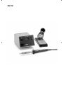
WSD 151

English
Thank you for placing your trust in our company by purcha-
sing the Weller Soldering Station WSD 151. Production was
based on stringent quality requirements which guarantee the
perfect operation of the device.
1. Caution!
Please read these Operating Instructions and the attached
safety information carefully prior to initial operation. Failure
to observe the safety regulations results in a risk to life and
limb.
The manufacturer shall not be liable for damage resulting
from misuse of the machine or unauthorised alterations.
The Weller Soldering Station WSD 151 corresponds to the EC
Declaration of Conformity in accordance with the basic safe-
ty requirements of Directives 2004/108/EC and 2006/95/EC.
2. Description
2.1 Control unit
The soldering station WSD 151 was specially developed for
soldering tasks with an extremely high heat requirement. The
150 W heater power combined with the optimal transfer of
heat to the soldering iron bit guarantees the high performan-
ce capability of the WSP 150 soldering iron. As an alternative
to the WSP 150, all the soldering tools listed in the list of
accessories can be connected to the unit. A microprocessor
makes operation simple and comfortable. The digital electro-
nic control system guarantees the best possible control per-
formance for various soldering tools. The soldering tools
themselves are recognized automatically by the soldering sta-
tion and assigned the corresponding control parameters. The
high-powered 24 V heating elements make excellent dynamic
performance possible, so that the soldering tools can be used
universally.
Various equipotential bonding possibilities for the soldering
iron tip, zero power switch and antistatic design of control
unit and iron complete the high quality standard. The possibi-
lity of connecting an external input unit further increases the
variety of functions of this soldering station. With the optional
input units WCB 1 and WCB 2 it is possible to implement time
functions, locking functions, etc. Integrated temperature
gauge and PC interface are included in the extended scope of
the input unit WCB 2.
The temperature for the WSP 150 soldering iron can be set
over the range from 50°C - 550°C via 2 buttons (Up/Down).
The adjustment range is automatically limited
to 450°C if a different soldering tool is connected. The setpo-
int and actual value are displayed digitally. A blinking red LED
in the display signals that the preset temperaturehas been
reached – this serves as a optical regulator. Constant illumi-
nation means that the system is heating up.
2.2 Soldering irons
LR 21: Our "standard” soldering iron. With a power
of 50 watts and a wide spectrum of
soldering tips (ET series) this soldering iron
can beused anywhere in the electronics
sector.
LR 82: High-performance 80 watt soldering iron
for soldering work with high heat require
ments. The soldering tip is attached by a
bayonet catch to ensure correct position
when using different tips.
WP 80: The soldering iron WP 80 / WSP 80 is
WSP 80 characterized by its capacity for reaching
the soldering temperature quickly and
precisely. Its slim design and heating power
of 80 watts makes universal usage possible
from extremely fine to high-temperature
soldering work. Work can be continued
immediately after switching soldering tips
since the temperature is reached again
quickly.
13
Technical Data
Dimensions in mm: 166 x 115 x 101 (l x w x h)
Supply voltage (8): 230 V / 50/60 Hz
240 V/120 V / 50/60 Hz (dual version)
100 V / 50/60 Hz
Power input: 150 W
Class: 1 (control unit) and 3 (soldering iron)
Fuse (9): 230 V; T800mA
240 V/120 V; T1,6A
100 V; T1,6A
Temp. control: 50°C - 550°C
Precision: ± 11°C
Equipotential bonding (6): Via a 3.5 mm jack bush (initial state-hard-grounded)

14
4. Equipotential bonding
The various circuit elements of the 3.5 mm jack bush (6)
make 4 variations possible:
Hard-grounded:
No plug (delivery form)
Equipotential bonding
(impedance 0 ohms):
With plug, equalizer at center
contact
Potential free:
With plug
Soft-grounded:
With plug and soldered
resistance.Grounding via set
resistance value.
5. Instructions for use
For initial heating, coat the selective tinnable tip with solder.
This removes any oxidation or dirt on the tip which may have
occurred during storage. During pauses between soldering
and before storing the soldering iron, ensure that the tip of
the soldering iron is well coated. Do not use aggressive flu-
xing agents.
Note: Always ensure the proper position of the soldering
iron tip.
These soldering irons have been adjusted for an average-
size tip. Deviations can occur due to exchanging of the tip or
using other tip designs.
External input unit WCB 2 (optional)
The following functions are possible when using an external
input unit.
Offset:
The real temperature of the soldering iron can be changed
by ± 40°C by input of a temperature offset.
Setback:
Reduction of the setpoint temperature to 150°C (standby).
The setback time can be set at 0-99 minutes after the sol-
dering station has switched to standby mode. After a period
equal to three times the set-back time, the ”Auto Off” func-
tion is activated. The soldering iron is switched off (flashing
dash on the display).
Lock:
Locking the setpoint temperature. Settings cannot be chan-
ged after the soldering station has been locked.
English
WSP 150: Special 150 W soldering iron for soldering
tasks with an extremely high heat
requirement. Easy to use shape combined
with high performance capability. Fast
warm-up time and precise temperature
regulation characterise the soldering
irons in this power range.
See "Accessories" for additional tools.
3. Starting
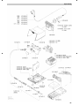
Assemble soldering iron rest (see exploded drawing).Place
the soldering iron in the safety rest. Insert the soldering iron
plug into the connection bush (6) of the control unit and lock
by turning to the right. Check that the power supply corre-
sponds to the specifications on the name plate and that the
power switch (1) is in the OFF position. On version that can
be switched, set the voltage on the selection switch (set in
the factory to 240 V). On version that can be switched, set
the voltage on switch (10) and insert the appropriate fuse
(9). Connect the control unit to the power supply. Switch on
the unit at the power switch (1). When switching on the unit,
a self-test is carried out in which all display elements (2) are
switched on briefly. The electronic system then switches
automatically to the actual temperature and displays this
value. LED (5) illuminates. These light emitting diodes are
optical regulator monitors. Constant illumination means that
the system is heating up. The blinking light signals that the
operating temperature has been reached.
Setting the temperature
The digital display (2) shows the actual value temperature.
By pressing the UP or DOWN key (3, 4) the digital display (2)
switches to the setpoint. The setpoint can be changed by
tapping or by firmly pressing the UP or DOWN button (3, 4)
in the desired direction. Pressing the button will change the
setpoint quickly. The digital display (2) returns automatically
to the actual value approximately 2 seconds after releasing
the button.
Standard setback:
Setting back the set temperature to 150°C. The setback
time, which follows the switching of the soldering station to
standby mode, is 20 minutes. After three setback times (60
minutes) the ”Auto-off” function is activated. The soldering
tool is switched off (blinking line on the display).
Setting: When switching on, hold the ”UP” key (3) until ON or
OFF appears in the display. Repeat this step to change.
Maintenance
The transition between the heating element / sensor and the
tip of the soldering iron may not come in contact with dirt,
foreign particles or become damaged, since this affects the
precision of the temperature control.

15
English
°C/°F:
Switching the temperature display from °C to °F, and vice
versa.
Window:
Limitation of the temperature range to max. ± 99°C based
on a locked temperature resulting from the "LOCK” func-
tion. The locked temperature represents the median point of
the adjustable temperature range.
Cal:
Re-adjustment of the soldering station (WCB 2 only).
PC interface:
RS232 (WCB 2 only).
Temp. gauge:
Integrated temperature gauge for thermal element Type K
(WCB 2 only).
6. Accessories
T005 29 170 98 Soldering Iron WSP 150
T005 29 161 99 Soldering iron set WSP 80
T005 29 180 99 Soldering Iron WP 80
T005 33 131 99 Soldering iron set MPR 80
T005 33 112 99 Soldering iron set LR 21, antistatic
T005 33 113 99 Soldering iron set LR 82
T005 33 133 99 Soldering iron set WTA 50
T005 27 028 99 Preheating plate WHP 80
T005 27 040 99 Soldering bath WSB 80
T005 25 030 99 Thermal insulating unit WST 20
T005 31 180 99 External input unit WCB 2
T005 33 155 99 Soldering iron set WMP
WPHT Stop and go iron stand (WMP)
7. Scope of supply
WSD 151 PUD 151
Control unit Control unit
Soldering iron WSP 150 Power cable
Power cable Operating instructions
Operating instructions Jack
Soldering iron rest Safety Information
Jack
Safety Information
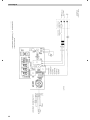
Illustration: Circuit diagram, see Page 61
Illustration: Exploded view, see Page 62
Subject to technical alterations and amendments!
See the updated operating instructions at
www.weller-tools.com.

61
Circuit Diagram

62
Explo-Drawing

www.weller-tools.com
Weller
®
is a registered Trademark and registered Design of Apex Tool Group, LLC.
© 2011, Apex Tool Group, LLC.
T005 56 805 07 / 09.2011
T005 56 805 06 / 01.2011
U S A
Apex Tool Group, LLC.
14600 York Rd. Suite A
Sparks, MD 21152
Phone: +1 (800) 688-8949
Fax: +1 (800) 234-0472
G E R M A N Y
Weller Tools GmbH
Carl-Benz-Str. 2
74354 Besigheim
Phone: +49 (0) 7143 580-0
Fax: +49 (0) 7143) 580-108
F R A N C E
Apex Tool Group S.A.S.
25 Av. Maurice Chevalier B.P. 46
77832 Ozoir-la-Ferrière, Cedex
Phone:+33 (0) 160.18.55.40
Fax: +33 (0) 164.40.33.05
G R E A T B R I T A I N
Apex Tool Group
(UK Operations) Ltd
4
th
Floor Pennine House
Washington, Tyne & Wear
NE37 1LY
Phone: +44 (0) 191 419 7700
Fax: +44 (0) 191 417 9421
I T A L Y
Apex Tool S.r.I.
Viale Europa 80
20090 Cusago (MI)
Phone: +39 (02) 9033101
Fax: +39 (02) 90394231
S W I T Z E R L A N D
Apex Tool Switzerland Sàrl
Rue de la Roselière 12
1400 Yverdon-les-Bains
Phone: +41 (0) 24 426 12 06
Fax: +41 (0) 24 425 09 77
A U S T R A L I A
Apex Tools
P.O. Box 366
519 Nurigong Street
Albury, N. S. W. 2640
Phone: +61 (2) 6058-0300
C A N A D A
Apex Tools - Canada
164 Innnisfil street
Barrie Ontario
Canada L4N 3E7
Phone: +1 (905) 455 5200
C H I N A
Apex Tool Group
A-8 building, No. 38 Dongsheng Road,
Heqing Industrial Park, Pudong
Shanghai PRC 201201
Phone: +86 (21) 60880288
Fax: +86 (21) 60880289
-
 1
1
-
 2
2
-
 3
3
-
 4
4
-
 5
5
-
 6
6
-
 7
7
-
 8
8
-
 9
9
-
 10
10
-
 11
11
-
 12
12
-
 13
13


Weller WSD 151 Operating Instructions Manual
- Taper
- Operating Instructions Manual
dans d''autres langues
- English: Weller WSD 151
Documents connexes
-
Weller wsd 81 Operating Instructions Manual
-
Weller WAD 101IG Operating Instructions Manual
-
-
-
-
-
-
Weller WSF 81 D8 Le manuel du propriétaire
-
-
