Broan EI5936SS Le manuel du propriétaire
- Catégorie
- Hottes
- Taper
- Le manuel du propriétaire

BR N
, _ Page 1
I................FI
ange ood
WARNING
FOR DOMESTIC
TO REDUCE THE RiSK OF FIRE, ELECTRIC SHOCK, OR iNJURY
TO PERSON(S) OBSERVE THE FOLLOWING:
1. Use this unit only in the manner intended by the manufacturer. If
you have questions, contact the manufacturer at the address or
telephone number listed in thewarranty.
2. Before servicing or cleaning unit, switch power off at service panel
and lock service disconnecting means to preventpower from being
switch on accidentally. When the service disconnecting means
cannot be locked, securely fasten a prominent warning device,
such as a tag, to the service panel.
3. Installation work and electrical wiring must be done by qualified
personnel in accordance with all applicable codes and standards,
includingfire-rated construction codes and standards.
4. Sufficient air is needed for proper combustion and exhausting
of gases through the flue (chimney) of fuel burning equipment to
preventback drafting. Followthe heatingequipment manufacturer's
guideline and safety standards such as those published by the
National Fire Protection Association (NFPA), and the American
Society for Heating, Refrigeration and Air Conditioning Engineers
(ASHRAE),and the localcode authorities.
5. This product may have sharp edges. Be careful to avoid cuts and
abrasions during installationand cleaning.
6. When cutting or drilling intowall or ceiling, do not damage electrical
wiring and other hidden utilities.
7. Ducted fans must always be vented to the outdoors.
8. Use only metal ductwork.
9. Do not usethis unit with any other solid-state speed control device.
10.This unit mustbe grounded.
TO REDUCE THE RiSK OF A RANGE TOP GREASE FIRE:
a) Never leave surface units unattended at high settings. Boilovers
cause smoking and greasy spillovers that may ignite. Heat oils
slowly on low or medium settings.
b) Always turn hood ON when cooking at high heator when flamb_ing
food (i.e. Cr_pes Suzette, Cherries Jubilee, Peppercorn Beef
Flamb_).
c) Clean ventilating fans frequently. Grease should not be allowed to
accumulate on fan or filters.
d) Use proper pan size.Always use cookware appropriate for the size
of the surface element.
TO REDUCE THE RiSK OF iNJURY TO PERSON(S) iN THE EVENT
OF A RANGE TOP GREASE FIRE, OBSERVE THE FOLLOWING*:
1. SMOTHER FLAMES with a close-fitting lid,cookie sheet, or metal
tray,then turn off the burner.BE CAREFUL TO PREVENT BURNS.
IF THE FLAMES DO NOT GO OUT IMMEDIATELY, EVACUATE
AND CALL THE FIRE DEPARTMENT.
COOKING ONLY
WA.NING &,
2. NEVER PICK UP A FLAMING PAN - You may be burned.
3. DO NOT USEWATER, includingwet dishcloths or towels- a violent
steam explosion will result.
4. Use an extinguisher ONLY if:
A. You know you have a Class ABC extinguisher, and you
know how to operate it.
B. The fire issmall andcontained inthe area where itstarted.
C. The fire department isbeing called.
D. You can fight the fire with your back to an exit.
* Based on "Kitchen Fire Safety Tips" published by NFPA
CAUTION
1. For indooruse only.
2. For general ventilating use only. Do not use to exhaust hazardous
or explosive materials and vapors.
3. To avoid motor bearing damage and noisy and/or unbalanced
impeller,keep drywall spray, construction dust, etc.off power unit.
4. Your hood motor has a thermal overload which will automatically
shut off the motor ifit becomes overheated.The motor will restart
when it will cool down. If the motor continues to shut off and
restart, have the hood serviced.
5. The bottom of the hood MUST NOT BE LESS than 24" and
recommended at a maximum of 36" above cooktop for best
capture of cooking impurities.
6. Two installers are recommended because of the size of this
hood.
7. To reduce risk of fire and to properly exhaust air, be sure to duct
air outside. Do not exhaust air intospaces within walls or ceilings
or into attics, crawl spaces, or garages.
8. Be careful when installingthe decorative flue and hood, they may
have sharp edges.
9. This hood is not intendedto be used as a shelf.
10. Please read specification label on product for further information
and requirements.
- Register your product online at: www.broan.corn -
Installer: Leavethis manual
with the homeowner.
Homeowner:Operationand Maintenance
instructionsonpages8 & g.

Page 2
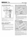
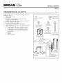
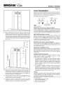
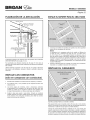
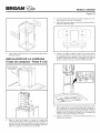
PLAN THE iNSTALLATiON iNSTALL THE CEiLiNG SUPPORT
ROOF CAP
\
6" ROUND
DUCT
///////////////////
DECORATIVE
FLUES
HOOD
\
\
EAVE
VENT
DUCT CENTERLINE
(l"torearofhoodcenterline)
T I_ HOOD
CENTER
LINE
24" TO 36" ABOVE
COOKING SUFACE
I I
The minimum hood distance above cooktop MUST NOT BE
LESS than 24'_
A maximum of 36" above cooktop is recommended for best
capture of cooking impurities.
Distances over 36" are at the installer and users discretion;
providing that the ceiling height permits.
Construct wood framing that is flush with interior surface of
the ceiling joists.
NOTE
Hood distance above cooktop is: Minimum 24'; Maximum
36': 9-10 ft. ceilings may require Flue Extension Model
FXNE59SS, depending on installation height (purchase
separately). Discard the upper and lower flues, mounting
frame, and trim strips supplied with your hood and replace
them with Flue Extension Model FXNE59SS.
2. Finish opening to match surrounding ceiling carefully marking
framing location.
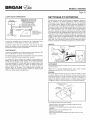
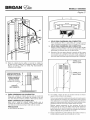
INSTALL THE WIRING
INSTALL THE DUCTWORK
(Ducted Hoods Only)
1. Decide where the ductwork will run between the hood and
the outside.
2. A straight, short duct run will allow the hood to perform most
efficiently.
3. Long duct runs, elbows and transitions will reduce the
performance of the hood. Use as few of them as possible.
Larger ducting may be required for best performance with
longer duct runs.
4. Install wall cap or roof cap. Connect round metal ductwork to
cap and work back towards the hood location. Use duct tape
to seal the joints between ductwork sections.
GROUNDING INSTRUCTIONS
This appliance must be grounded. In the event of an electrical
short circuit, grounding reduces the risk of electric shock by
providing an escape wire for the electric current.
Position the electrical (house wiring) within the space covered by
the decorative flue and where it will not interfere with the round
duct. Make sure the length of the house wiring is a minimum of 5
feet. It may be shortened after hood is installed at correct height
and electrical connection is made.

Page 3
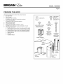
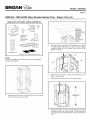
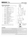
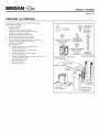
PREPARE THE HOOD
Unpack hood and check contents. You should receive:
1 - Hood Assembly
1 - Glass Canopy
1 - Decorative Flue Assembly
(consisting of 2-upper and 2-lower flue sections)
1 - Hood Frame Assembly
(consisting of upper and lower sections)
2 - Upper Flue Trim Strips
2 - Lower Flue Trim Strips
1 - Aluminum Grease Filter (installed on hood)
4 - 35W MR16 GUIO Halogen Lamps (included on hood)
1 - Parts Bag containing:
6- Mounting Screws(4ram x 38ram Cross Recessed Pan Head)
3- Mounting Screws(4ram x 12ramCross Recessed Pan Head)
12- Mounting Screws (3ram x 5ram Cross Recessed Pan Head)
4 - Mounting Screws (.188" x .250" Cross Recessed Flat Head)
1 - Suction CupTool
3- Wire Nuts
1 - Installation Manual
_ 3 MOUNTING
SCREWS
3WIRE NUTS (4mm x 12mm
Cross Recessed
Pan Head)
BULB SUCTION
CUPTOOL
12MOUNTINGSCREWS
(3rnmx 5ramCross
RecessedPanHead)
HOOD
FRAME ASSEMBLY
4MOUNTING
SCREWS
(.188"x .250"
CrossRecessed
FlatHead)
CANOPY
6 MOUNTING
SCREWS
(4mm x 50mm
Cross Recessed
Pan Head)
E
ASSEMBLY

BReAN o ss
Page 4
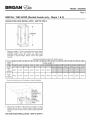
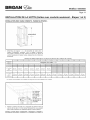
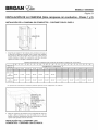
iNSTALL THE HOOD (Ducted hoods only- Steps 1 & 2)
NON=DUCTED HOOD iNSTALLATiON =SKiP TO STEP 3.
LENGTH
1. Determine length "L?of frame assembly based upon desired
installation height. (See chart below.) To adjust frame
assembly height, remove (8) screws, slide upper frame
assembly to required height, replace screws and tighten
securely.
Ceiling
Height
8 Feet
9 Feet
9 Feet
with
FXNE59SS
10 Feet
with
FXNE59SS
Desired Hood Distance (Above 36" HighCooktop)
24" I 25" I 26" I 27" I 28" I 29" I 30" I 31" I 32" I 33" I 34" I 35" I 36"
44-5/8" 43-5/8" 42-5/8" 41-5/8" 40-5/8" 39-5/8" 38-5/8" 37-5/8" 36-5/8" 35-5/8" 34-5/8" 33-5/8" 32-5/8"
* Non-duct recirculation louvers will be exposed in ducted configuration
2. Align frame assembly to ceiling framing, and attach to ceiling
framing with (6) 4ram x 50mm screws. Tighten securely,
making sure that the upper frame bracket is tight against the
ceiling.
DUCTED HOOD INSTALLATION =SKiP TO STEP 9.

Page 5
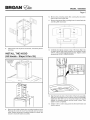
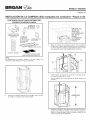
iNSTALL THE HOOD (Non-Ducted Hoods Only - Steps 3 thru 8)
NON=DUCT KiT MODEL RKE59 CONTENTS
NON-DUCTPLENUM
ASSEMBLY
4 MOUNTING
SCREWS
(.188"x .375"
CrossRecessed
FlatHead)
4 MOUNTING (_
SCREWS
(3mm x 10mm
Cross Recessed
Pan Head)
4 FOAM
RECTANGLES
FILTERTRAY
FLEXIBLEDUCT
NON-DUCTED RECIRCULATION FILTERS
NOTE
Non-ducted installations require Non-Duct Kit, Model RKE59
(purchase separately).
®
4_
@
3. Disassemble the frame by removing (8) screws. Set aside
screws and lower frame assembly.
4.
Align upper frame assembly to ceiling framing, and attach
to ceiling framing with (6) 4mm x 50mm screws. Tighten
securely, making sure that the upper frame bracket is tight
against the ceiling.
5. Install non-duct plenum to upper frame bracket using (4)
3mm x 10mm screws.
6. Feed house wiring around front of non-duct plenum.
7.
J j-
LENGTH
Determine length %:'of frame assembly based upon desired
installation height. See chart on page 4. Slide lower frame
over upper frame and attach with (8) screws previously set
aside.

Page 6
8. Attach foam seals to plenum and frame, around the plenum
openings.
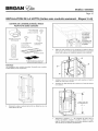
INSTALL THE HOOD
(All Hoods - Steps 9 thru 25)
10.
11.
12.
Remove the protective plastic film covering the decorative
flue and the hood at this time.
Remove the grease filter by pulling down the metal latch tab
and tilting filter downward.
Carefully place glass canopy on top of the hood. Align nuts
on glass canopy with holes inside the hood. Attach canopy
with (4) .188" x .250" long flat head screws. Tighten screws
securely but DO NOT OVERTIGHTEN.
ELECTRONICS
MOUNTING
BRACKET_
9,
Remove tape holding electronics mounting bracket to hood.
Remove (3) screws on top of hood chassis and set screws
aside. Rotate electronics mounting bracket as shown and
secure to hood with same (3) screws.
13. Align the keyhole slots on the bottom of the frame assembly
with the (4) mounting screws on the top of the hood (partially
tightened). Slide the hood so the screw heads are seated
entirely on mounting screws and that hood is level. Then
tighten screws completely.
14. Install (1) 4mm x 12mm long screw into the lower frame and
hood to secure.

BR N o ss
Page 7
17. NON-DUCT HOOD ONLY
Attach filter tray to bottom of hood using (4) .188" x .375"
mounting screws.
18. NON-DUCT HOOD ONLY
Snap in 2-non-duct filters into filter trays by engaging filter
tab on side, rotating upward, and pressing firmly on (2) filter
clips.
19. Reinstall grease filter by aligning rear filter tab with slots
in the hood. pull down the metal latch tab, push filter into
position and release. Make sure filter is securely engaged
after installation.
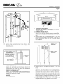
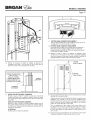
15. Remove wiring cover and connect house wiring to hood
wiring - black to black, white to white, green to green. Re-
attach wiring cover.
A
6" ROUND STEEL DUCT |
(Ducted Hood) ------------z___/
6" ROUND FLEXIBLE
METAL DUCT
(Non=Ducted Hood)
DUCTLENGTH
li
DECORATIVE
FLUE
L . I
16. FOR DUCTED HOOD
Measure, cut, and install steel duct between hood's duct
connector and duct rough-in in ceiling. Use duct tape to
make all joints secure and air tight.
FOR NON-DUCTED HOOD
Measure, cut, and install flexible metal duct between hood's
duct connector and non-duct plenum. Use duct tape to
make all joints secure and air tight.
CAUTION
Do not use plastic duct.
------.---.__._.
111111
------.-_.___.
.,,_---------4mm x 12mm
SCREWS
3mm x 5mm
SCREWS
20. Carefully place the (2) upper flue sections on the hood
frame.
Note that the louvers should be on top for a non-ducted
application, and on the bottom for most ducted applications.
Make sure that the clearance holes (larger) are in front of the
attachment holes (smaller) where the two flue halves meet.
While gently pushing the two flue sections together and
sliding them to the top of the frame, attach the flue sections
together through the top attachment slots and into the upper
frame mounting holes using (2) 4ram x 12ram screws.
21. Gently push the lower parts of the flues together and
complete attachment using (6) 3mm x 5ram screws.

Page 8
22. Carefully place the (2) lower flue sections on the hood frame,
and overlapping the outside of the upper flue assembly, and
nested into the glass cutout. Make sure that the clearance
holes (larger) are in front of the attachment holes (smaller)
where the two flue halves meet. While gently pushing the
two flue sections together, attach the flue sections using (6)
3mm x 5mm screws.
OPERATION
Always turn the hood ON before cooking in order to establish an air
flow in the kitchen.After turning off the range, letthe hood runfor a few
minutes toclear the air.
Operatethe hoodas follows: DELAY
OFF FAN OFF LIGHT
®
OFF LED INDICATORS
Turnsthe fan OFF
FAN (1-Pushbutton Switch, 3-Fan Speeds)
Turnsthe fan ON to the last selected speed, and activatesa blue LED
indicating the fan speed setting.Pressingthe FAN button a second time
will index the fan speed and LED indicator to the next highest setting.
Pressingthe FANbutton when the fan is at the highest speed settingwill
index the fan and LEDindicator tothe lowestsetting.
DELAY-OFF(10Minute Delay-OFF)
Activatesthe 10minutedelay off featurewhen the fan isON (anyspeed).
When activated,the blue LED indicatorabove the selectedspeed setting
will blink.The hood fan will automatically turn OFF after 10 minutes has
elapsed.The DELAY-OFFbutton can be pressedat any time during the
10 minutecountdown toturn off the feature.
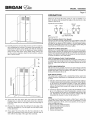
(A)
////////
(A)
//
//
//
/
/
,//
23. Snap lower flue trim strips (thin) into lower flue channels.
Engage tabs on strips into slots inside lower flue channels.
Push trim strips down so top edge is even with top edge of
lower flue.
24. Measure the distance from the ceiling to the top edge of the
lower flue assembly (A). Cut the upper flue trim strips (wide)
to this dimension.
25. Snap upper flue trim strips into the flue channels in the
upper flue assembly. Ensure that the top of the trim strip is
even with the top edge of the upper flue assembly.
LIGHT (1-PushbuttonSwitch, 3-Light Intensities)
Turnsthe lights ON to the lowest intensity.Pressing the LIGHT buttona
secondtime will indexthe light intensitytothe next highestlevel.Pressing
the LIGHT buttonwhen the lightsare atthe highest intensity will turn the
lightsoff.
FILTERCHANGE INDICATION
After 30 hours of fan operation, the three blue LED indicators will blink
simultaneously,indicatingthatit istime toclean the greasefilters.Toreset
the filter clean timer, press and hold the OFF button for 3 seconds.The
blinking LED indicatorswill turn off.
HEATSENTRY SYSTEM
This range hood is equipped with a standard Heat Sentry system that
monitors excessive temperature and automatically turns the fan speed
on HIGH.
1) If the fan isON, the HeatSentry systemwill increasethe fan settingto
it'shighestspeedwhenthe temperatureiselevated.The blueindicator
for fan speed (3) will illuminate and blink at a high rate, indicating
that the heat sentry function is activated. Once the temperature has
reduced, the Heat Sentry system will change the fan speed to the
original setting.
2) If the fan is OFF,the Heat Sentry systemwill automatically turn the
fan on to it's highest speed when the temperature is above normal.
The blue indicator forfan speed (3) will illuminateand blinkat a high
rate, indicating that the heat sentry function is activated. After the
temperature haslowered to normal,the fan will turn off.
FUSES
The Range Hood Control Board contains a Main Fuse to protect the
controls from power surges. New fuses can be purchased at a local
electronic supply store.Use5A, 120V,5 mm diameter, 20 mm long, fast-
acting,cartridge-type fuses.
Toreplacea fuse (by qualified person(s)):
1. Disconnectpower at service entrance.
2. Removedecorative flues.
3. Removecontrol cover
4. Removeand inspectfuse.

Page 9
MAKE-UP AiR DAMPER
GR
MODEL EW56, EW58, EI59 SERIES
MAKE-UPAIR DAMPER MAKE UP DAMPER CONNECTION
= (switched low voltage)
20 GAUGE BELLWIRE FOR LOW
I I [_ VOLTAGE CONNECTION ON
TOP OF HOOD0,
_]_ TRANSFORMER / I_ DRY CONTACT
J4111 (INCLUDED)/ I TERMINAL
)/I ttl / HOOD I BUSHING
L44-J / I FORLOW
I L 120 VAC ,/ I VOLTAGE
60 HZ [ I CONNECTION
The hoodis compatiblewith Broan Make-UpAir DamperModel MD6Tor
Model MDST(optional).Purchaseseparately.
Make the connection to the Make-Up Air Damper with low voltage
wiring, as shown. See Make-Up Air Damper instructions for additional
information.
REMOTE CONTROL
The hood is compatible with Broan Radio Frequency (RF) Remote
Control Model BCR1(optional).Purchaseseparately.
Tolink the BCR1 remotecontrol withthe hood,pressand holdthe LIGHT
buttonfor 3-seconds.
The blue LED indicatorswill turn on and off insuccession toindicate the
hood is in RF linkingmode.When in the linking mode, pressany keyon
the RF remote.An audible beep will be heard atthe hood, and the hood
LED'swill stop blinking ifa successful link isaccomplished. Ifthe remote
control did not successfully link with the hood, the linking mode will be
deactivated after 12 seconds, and the LED's will stop the sequential
blinking.Referto the BCR1 instructions foradditional information.
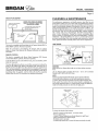
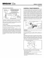
CLEANING & MAINTENANCE
For performance, appearance,and health reasons, clean filter, fan and
grease-ladensurfaces.Useonly aclean clothand milddetergent solution
on stainlessand paintedsurfaces.Cleanall-metalfilters inthe dishwasher
using a non-phosphate detergent.Discoloration of the filter may occur if
using phosphatedetergents, or asa resultoflocal waterconditions- but
thiswill not affectfilter performance.This discoloration is not covered by
the warranty. Clean the non-duct recirculating filter surfaces frequently
with a damp cloth and a mild detergent. DO NOT immerse filters in
water or put in dishwasher. Change the non-duct recirculating filters
every6 months.For replacementnon-duct recirculatingfilters- purchase
$99010365 or Model FILTERE56.The motor is permanently lubricated
andnever needsoiling. Ifthe motor bearingsmake excessiveor unusual
noise, replacethe blowerassembly with an exact service replacement.
LIGHTBULBS
SUCTION CUP TOOL
HALOGEN
\ ROTATE
CLOCKWISE_
WARNING
Bulbs maybe hot.Always allow bulbs tocool down beforeremoving
them.
Use (2) Halogen Bulbs (included with hood) - 120 V, 35 W, shielded
halogenbulbs- MR16 with GU10 base.
NOTE
Suction CupTool(includedwith hood)can be usedto installand
removelight bulbs.Align pinson bulbwith largediameter opening
on socket,thenpush bulb in towards hoodand rotateclockwise until
firmly seated.The positionof the bulb socket (depth)is adjustable and
may requireadjustment when: a) certain brandsof bulbsare difficultto
install,b) the bulb protrudes too farbelowthe light panel.
LAMP SOCKET
BRACKET
LIGHT
PANEL
SCREWS
Tochange the depth of bulb sockets:
- Remove2 screwson lightpanel- set screwsaside
- Remove Light Panel.
- Loosen 2 Screws holding Lamp SocketBracketto Light Panel.
- Adjust socket/bracketto desired depth.
- Re-tightenscrews securely.
- Re-attachlight panelwith 2 screwsthat were previouslyset aside.

BR N o ss
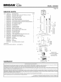
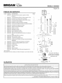
SERVICE PARTS
KEY PART NO.
1 S99527476
2 S99527477
3 S99527479
4 S99527478
5 S99527443
6 S99527444
7 S99527445
8 S99527446
9 S99527447
10 S99527449
11 S99527450
12 S99527454
13 S99010366
14 S99010365
15 S99527459
16 S99527460
17 S99527461
18 S99527462
19 S99527465
20 S99526798
21 S99527468
* S99527470
* S99527471
* S99527474
* S99527481
* Not shown.
DESCRIPTION QTY.
Decorative Upper and Lower Flues (2 of each) 1
Upper Flue Trim (2 pcs.) 2
Hood Frame Assembly 1
Lower Flue Trim (2 pcs.) 2
Motor / Blower Assembly 1
Light Socket (includes mounting hardware) 4
Light Socket Bracket (includes mounting hardware) 4
User Interface Assembly 1
User Interface Cable 1
Control Board 1
Control Enclosure 1
Light Panel (pair) 2
Aluminum Grease Filter 1
Non-Duct Recirculation Filters (pair) 1
Non-Duct Filter Tray 1
Curved Glass Plate 1
Damper Assembly 1
6" Dia. Expandable Flexible Aluminum Duct 1
Non-Duct Plenum Assembly 1
35W MR16 GU10 Halogen Lamp 4
Capacitor 1
Heat Sensor 1
Fuse 1
Parts Bag 1
User Interface Button (4-pack) 4
Order service parts by Part No. - not by Key No.
Page 10
4
17_
16 11
lO
1 19
7 _ _ _
6_ _ _---._ 12
,&
Replacement
parts can be ordered
5 on our website:
www.broan.com
WARRANTY
BROAN-NUTONEONEYEARLIMITEDWARRANTY
Broan-NuTonewarrantsto theoriginalconsumerpurchaserofitsproductsthatsuchproductswill befreefromdefectsinmaterialsorworkmanshipfora periodof oneyearfromthedateoforiginalpurchase.THEREARENO
OTHERWARRANTIES,EXPRESSORIMPLIED,INCLUDING,BUTNOTLIMITEDTO,IMPLIEDWARRANTIESOFMERCHANTABILITYORFITNESSFORAPARTICULARPURPOSE.
Duringthisone-yearperiod,Broan-NuTonewill,atitsoption,repairor replace,withoutcharge,any productor partwhichisfoundtobedefectiveundernormaluseandservice.
THISWARRANTYDOESNOTEXTENDTOFLUORESCENTLAMPSTARTERS,TUBES,HALOGENANDINCANDESCENTBULBS,FUSES,FILTERS,DUCTS,ROOFCAPS,WALLCAPSANDOTHERACCESSORIESFORDUCTING.
Thiswarrantydoesnotcover (a)normalmaintenanceandserviceor (b) anyproductsor partswhichhavebeensubjectto misuse,negligence,accident,impropermaintenanceor repair(otherthan byBroan-NuTone),faulty
installationorinstallationcontraryto recommendedinstallationinstructions.
Thedurationofanyimpliedwarrantyis limitedtotheone-yearperiodasspecifiedfortheexpresswarranty.Somestatesdonotallowlimitationon howlonganimpliedwarrantylasts,sotheabovelimitationmaynotapplytoyou.
BROAN-NUTONE'SOBLIGATIONTOREPAIRORREPLACE,ATBROAN-NUTONE'SOPTION,SHALLBETHEPURCHASER'SSOLEANDEXCLUSIVEREMEDYUNDERTHISWARRANTY.BROAN-NUTONESHALLNOTBELIABLE
FORINCIDENTAL,CONSEQUENTIALORSPECIALDAMAGESARISINGOUTOFORINCONNECTIONWITHPRODUCTUSEORPERFORMANCE.Somestatesdonotallowtheexclusionorlimitationofincidentalor consequential
damages,sotheabovelimitationor exclusionmaynotapplytoyou.
Thiswarrantygivesyouspecificlegalrights,andyoumayalsohaveotherrights,whichvaryfromstatetostate.Thiswarrantysupersedesallpriorwarranties.
Toqualifyforwarrantyservice,youmust(a)notifyBroan-NuToneattheaddressor telephonenumberbelow,(b)givethemodelnumberandpartidentificationand(c)describethe natureofanydefectintheproductorpart.At
thetimeof requestingwarrantyservice,youmustpresentevidenceoftheoriginalpurchasedate.
Broan-NuToneLLC,926W.StateStreet,Hartford,Wisconsin53027 www.broan.com800-558-1711
Broan-NuToneCanada,Inc.,1140TristarDrive,Mississauga,OntarioLST1H9www.broan.ca877-896-1119

BR N
, , ._ _ Page 11
Hotte.de cuisine a [................[i
them=nee pour =lot
POUR USAGE DOMESTIQUE SEULEMENT
AVE,TISSEME.T AVE,TISSEME.T
AFIN DE REDUIRE LES RISQUES D'INCENDIE, DE DECHARGES
ELECTRIQUESOUDEBLESSURESCORPORELLES,VEUILLEZOBSERVER
LESDIRECTIVESSUIVANTES:
1. N'utilisezcetappareilquedela mani_repr_vueparle fabricant.Sivous
avezdes questions,communiquezavecle fabricant_.I'adresseou au
num_rodet_16phoneindiqu6sdansla garantie.
2. Avant de proc6der_.I'entretienou au nettoyagede I'appareil,coupez
I'alimentationdupanneau_lectriqueetverrouillezI'interrupteurprincipal
afin d'emp_cherquele courantnesoit accidentellementr_tabli.S'il est
impossible de verrouiller I'interrupteur principal, fixezsolidement un
messaged'avertissement,par exempleune6tiquette, sur le panneau
61ectrique.
3. [_'installationetlesbranchements61ectriquesdoivent8treeffectu_spar
un personnelcompetent,conform_mentaux normeset aux codesen
vigueur,y compris les normeset les codes du b&timentrelatifs _.la
r_sistanceaufeu.
4. Pour_viterlesrefoulements,I'apportd'airdolt_,tresuffisantpour brQler
les gazproduits parlesappareils_.combustionet les _vacuerdans le
conduitde fum_e (chemin_e).Respectezles directivesdu fabricant de
I'appareilde chauffage et les normesde s6curit_, notamment celles
publi_esparla NationalFireProtectionAssociation(NFPA),I'American
Society for Heating, Refrigeration and Air Conditioning Engineers
(ASHRAE)etlescodesdesautorit_slocales.
5. Ceproduit peutcomporter des arF,tes tranchantes. Prenezgardeaux
coupuresetaux_rafluresIorsdeI'installationet du nettoyage.
6. Veillez _. ne pas endommager le c_.blage_lectrique ou d'autres
6quipementsnon apparentsIors de la d6coupeou duper_agedu tour
oudu plafond.
7. Lesventilateurscanalis_sdoiventtoujoursrejeterrair _.I'ext_rieur.
8. N'utilisezquedesconduits m_taliiques.
9. N'utilisezpas de commandede r_gime_.semi-conducteurs aveccet
appareil.
10. Cetteunit_dolt _,treraise_.laterre.
POURREDUIRELESRISQUESD'INCENDIECAUSESPARDELAGRAISSE
SURLEPLANDECUISSON:
a) Nelaissezjamaisles 61_mentsdesurface allum_s_.hautetemperature.
Les d_bordementspeuvent causer de la fum6e et occasionner des
6coulements de graisse inflammables. I_huile dolt _,tre chauff_e
graduellement_.basseou _.moyennetemperature.
b) Metteztoujours la hotte en MARCHEIors d'une cuisson _.feu vif ou
Iorsdela cuissond'aliments&fiamber(par ex.,cr_pesSuzette,cerises
jubil_, boeufaupoivreflamb_).
c) Nettoyezsouvent la hotte. Nelaissezpas la graisses'accumulersur le
ventilateuroules filtres.
d) Utilisezdescasserolesdedimensionappropri_e.Utiliseztoujours une
batteriedecuisineadapt_e_.la dimensiondela surfacechauffante.
OBSERVEZLESCONSIGNESSUIVANTESAFINDEREDUIRELESRISQUES
DEBLESSURESCORPORELLESENCASD'INCENDIECAUSEPARDE LA
GRAISSESURLEPLANDECUISSON:*
1. ETOUFFEZLESFLAMMES_.I'aide d'un couvercle_tanche,d'unet61e
_.biscuits ou d'un plateau en m6talpuis _teignezle brQleur.FAITES
ATTENTIONDE NE PAS VOUS BRULER. SI LES FLAMMES NE
S'ETEIGNENTPASIMMEDIATEMENT,QUITTEZLESLIEUXETAPPELEZ
LESERVICEDESINCENDIES.
2. NESOULEVEZJAMAIS UNECASSEROLEENFLAMMES- vous pourriez
vous brQler.
3. N'UTILISEZPAS D'EAU,ni de serviettes ou de tinges mouill_s - une
violenteexplosiondevapeurpourrait survenir.
4. UtilisezunextincteurSEULEMENTsi :
A) Vous savezqu'il est declasseABCet que vous connaissezd_j_ son
modedefonctionnement.
B) 12incendien'estpastr_s importantet nese propagepas.
C) Lespompiersont _t_avis_s.
D) VouspouvezcombattreI'incendieenfaisantdos_.unesortie.
* Conseilstir_s dela publicationdela NFPA_<KitchenFireSafetyTips >>.
ATTENTION
1. Pour usageint_rieur seulement.
2. Pourventilation g_n_rale uniquement. Nepasutiliser cet appareilpour
_vacuerdes mati_resou desvapeurs dangereusesou explosives.
3. Pour ne pasendommager les roulements du moteur, d_s_quiiibrer les
pales ou les rendre bruyantes, prot_gez rappareil de la poussi_re de
plb,tre, de construction, etc.
4. Le moteur de ia hotte est muni d'un dispositif de protection de
surcharge _lectrique qui coupe automatiquement le moteur en cas de
surchauffe, li se remet en marche iorsqu'ii a refroidi. Faitesr_parer la
hottesi le moteur continue b,fonctionner parintermittence.
5. Pourmieux capter lesvapeurs decuisson, le basdelahotte DOlTETRE
AU MINIMUM b.61 cm (24 po) etarecommand_au maximum b,91 cm
(36 po) au-dessus de lasurface de cuisson.
6. IIest recommand_que les installateurs soient deux, compte tenu de la
taille de cettehotte.
7. Pour r_duire ies risques d'incendie et _vacuer rair correctement,
assurez-vous qu'il est canalis_ b.rext_rieur. Ne pas _vacuerrair dans
des espacesenferm_spardes murs ou un plafond ou dans un grenier,
unvide sanitaire ou un garage.
8. Prenezgardeen installant la chemin_e d_corative et la hotte, car eiles
peuventcomporter des bords tranchants.
9. Cette hotte n'est pas con(_uepour servir d'_tag_re.
10.Veuillezlire r_tiquette despecifications du produit pour obtenir plusde
renseignements, notamment sur les exigences.
- Enregistrez votre produit en ligne & : www.broan.corn
Installateur •Veuillezremettrece
manuel auprepri taire.
Prepri taire •Directivesd'entretien et
d'utilisatien la pages18 et 19.

BR N , o oss
Page 12
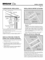
PLANIFICATIONDE L'INSTALLATION iNSTALLATiONDU SUPPORT AU PLAFOND
CAPUCHON DETOIT
\
CONDUIT ROND
DE 15cm (6 po)
CONDUIT
DECORATIF I
\
EVENT
DAVANTTOIT
HOTTE
\
LIGNE CENTRALE DU CONDUIT
(2,5 cm [1 po] A I'arri_re de la ligne
centrale de la hotte)
DE LA HOTTE
61A 91 cm (24 ,A,36po) AU-DESSUS
DE LA SURFACE DECUISSON
I I
La distance minimale de la hotte au-dessus de la surface de cuisson NE
DOlT PAS ETRE INFCRIEURE & 61 cm (24 po).
II est conseille de ne pas la placer b,plus de 91 cm (36 po) pour mieux
capter les vapeurs de cuisson.
Une distance de plus de 91 cm (36 po) est laissee a la discretion de
I'installateur et des utilisateurs si la hauteur du plafond le permet.
1. Construisez une charpente de bois qui affleure la surface int@ieure
des solives du plafond.
2,
REMARQUE
La distance de la hotte au-dessus de la surface de cuisson est :
au minimum de 61 cm (24 po) et au maximum de 91 cm (36 po).
Les plafonds de 2,7 m (9 pi) et 3 m (10 pi) necessitent la rallonge
de conduit decoratif, modele FXNE59SS, selon la hauteur de
I'installation (vendue separement). Jetez les conduits decoratifs
sup@ieur et inferieur, le cadre de montage et les bandes de finition
fournis avec votre hotte et remplacez-les par la rallonge de conduit
decoratif, modele FXNE59SS.
Finissez I'ouverture pour qu'elle affleure le reste du plafond en
marquant soigneusement la position de la charpente de bois.
INSTALLATION DU CABLAGE
INSTALLATION DES CONDUITS
(hottes avec conduits seulement)
1,
2.
3.
4,
Planifiez la pose du conduit en determinant son trace entre la hotte
et I'ext@ieur de la maison.
Un trace droit et court permet & la hotte d'etre plus efficace.
Des conduits longs, des coudes et des transitions reduisent
I'efficacite de la hotte. N'en utilisez que le moins possible. Pour plus
d'efficacite, des conduits plus gros peuvent _tre necessaires si le
parcours est trop long.
Installez le capuchon mural ou de toit. Connectez un conduit fond
en metal au capuchon en progressant vers la hotte. Scellez les
joints avec du ruban & conduit b,chaque section.
INSTRUCTIONS DE MISE ,_ LA TERRE
Cet appareil dolt 6tre correctement mis & la terre. Dans I'eventualit6 d'un
court-circuit, la mise b, la terre reduit les risques de decharge electrique
en permettant au courant de s'echapper dans un ill.
Placez le c&ble electrique (de la maison) dans I'espace recouvert par
le conduit decoratif de cheminee et & un endroit ou il ne nuira pas au
passage du conduit fond. Assurez-vous que le c&ble de la maison ait
au moins 1,5 m (5 pieds). Une lois I'installation terminee, II pourra &tre
raccourci b,la Iongueur adequate pour effectuer la connexion electrique.

BR N , o oss
Page 13
PRE PARATION DE LA HOTTE
Deballez la hotte et v@ifiez le contenu de la boite. Celle-ci dolt contenir
les el6ments suivants :
1 - Hotte assemblee en usine
1 - Capot en verre
1 - Ensembled de conduit decoratif de cheminee (2 conduits
sup@ieurs et 2 conduits inferieurs)
1 - Cadre de montage de la hotte (sections sup@ieure et inferieure)
2 - Bandes de finition du conduit sup@ieur
2 - Bandes de finition du conduit inferieur
1 - Filtre & graisse en aluminium (installes dans la hotte)
4 - Lampes halogenes MR16 GU10 de 35 W (installees dans la hotte)
1 - Sac de pieces contenant :
6 - Vis de montage (4 x 38 mm a t6te cylindrique cruciforme)
3 - Vis de montage (4 x 12 mm a t_te cylindrique cruciforme)
12 - Vis de montage (3 x 5 mmb. t_te cylindrique cruciforme)
4 - Vis de montage (0,47 x 0,64 cm (0,188 x 0,250 po) b,t_te
plate cruciforme)
1 - Ventouse
3 - Serre-fils
1 - Manuel d'installation
3 SERRE-FILS
?
12VIS DEMONTAGE
(3 x 5 mm b.tCte
cylindrique cruciforme)
ENSEMBLE DE CADRE
DE HOTTE
3 VlS DE MONTAGE
(4 x 12 mm a t_te
cylindrique cruciforme)
VENTOUSE
POURAMPOULE
?
4 VlS DE MONTAGE
(0,47 x 0,64 cm
(0,188x 0,2.50po)
C
6 VlS DE MONTAGE
tCte plate cruciforme) (4 x 50 mm a tCte
cylindrique cruciforme
CAPOT EN VERRE
ENSEMBLE
DE HOTTE
BANDESDE
FINITIONDE
CONDUIT
CONDUIT
DECORATIF
DE CHEMINEE
ENSEMBLE DE
CONDUIT DECORATIF
DECHEMINEE

BR N , o oss
Page 14
iNSTALLATiON DE LA HOTTE (Hottes avec conduits seulement =Etapes 1 et 2)
iNSTALLATiON AVEC SANA CONDUITS= PASSEZ ._,L'ETAPE 3.
i ............ T-
'i
LONGUEUR
,, L _
Determinez la Iongueur _ L _ de I'ensemble de cadre selon la
hauteur d'installation souhaitee. (Voir le tableau ci-dessous.)
Pour regler la hauteur du cadre, enlevez les huit (8) vis, glissez la
section sup@ieure b,la hauteur voulue, replacez les vis et serrez-les
fermement.
Distance de hotte requise [91,4 cm (36 po) au-dessus de la surface de cuisson]
_1c,./24poll_._,_cm/2_poll_6_m/_6po/I_,__m/_,po/I.,__/__o/I_._,__m/_po/b2cm/_opo/I_,__m/_po/l_,3_,./_po/I_3,__,./_3po/l_,__m(34po)188,ecm(sspo)lel,4cm (36DO)
Hauteur du
plafond Longueur du cadre <<L >>
2,4 m (8 pi) *52,4crn(20-5/8F149,Scm(19-s/Spo) 47,3crn(18.5/Spo) 44,Scrn(17-5/Spo) 42,2crn(16.s/Spo) 39,Tcm(15-5/spo[ I I .
2,7 m (9 pi) '60,0c_Y_(234/8_)%7,Scrrl(22.5/spo)%4,9cm(21.5/81}o)%2,4crrl(20-5/spo}
_,_i_ 82,9cm80,3o_77,8_ 75,2cm72,7c_70,2cm87,8o_
avec (32-5/8po) (31-5/8 po) (30-5/8po) (29-5/8 po) (28-5/8po) (27-5/8po) (26-5/8po) ...........................................
FXNE59 SS
3 m (10 pi) 113,3 cm 110,8 cm 108,3 cm 105,7 cm 103,2 cm 100,6 cm 98,1 cm 95,6 cm 93,0 cm 90,5 cm 87,9 cm 85,4 cm 82,9 cm
avec (44-5/8 po) (43-5/8 po) (42-5/8 po) (41-5/8 po) (40-5/8 po) (39-5/8 po) (38-5/8 po) (37-5/8 po) (36-5/8 po) (35-5/8 po) (34-5/8 po) (33-5/8 po) (32-5/8 po)
FXNE59SS
Les events de recirculation sans conduits sont exposes Iors d'une installation avec conduits
2. Alignez le cadre de la hotte sur la charpente du plafond et fixez-le
avec six (6) vis de 4 x 50 mm. Serrez fermement en vous assurant
que le cadre sup@ieur est solidement appuye contre le plafond.
iNSTALLATiON AVEC CONDUITS =PASSEZ ._,L'€:TAPE9.

BR N , o oss
Page 15
iNSTALLATiON DE LA HOTTE (Hottes sans conduits seulement =Etapes 3 _ 8)
CONTENU DE L'ENSElVIBLE MODELE RKE59
POUR HOTTE SANS CONDUITS
ENSEMBLEDECAISSON
NONCANALISE
i
CONDUITFLEXIBLE
4 VIS DEMONTAGE
(3 x 10mma t_te
cylindriquecruciforme)
4 VlS DE MONTAGE 4 RECTANGLES
(0,47x 0,98cm DEMOUSSE
(0,188 x 0,378 po)
t_teplate cruciforme)
PLATEAU DE FILTRE
FILTRES DE RECIRCULATION POUR
INSTALLATION SANS CONDUITS
REIVlARQUE
Les installations sans conduits necessitent I'ensemble sans conduits,
modele RKE59 (vendu separement).
®
4}
®
3. Demontez le cadre en enlevant les huit (8) vis. Mettez les vis et le
cadre inferieur de c6t&
4. Alignez le cadre sup@ieur sur la charpente sur plafond et fixez-le
avec six (6) vis de 4 x 50 ram. Serrez fermement en vous assurant
que le cadre sup@ieur est solidement appuye contre le plafond.
5,
6.
_,::D //"
Installez le caisson non canalise sur le cadre sup@ieur b,I'aide de
quatre (4) vis de 3 mm x 10 mm.
Acheminez le c&ble electrique de la maison sur I'avant du caisson
non canalis&
, °
Determinez la Iongueur _, L _ de I'ensemble de cadre selon la
hauteur d'installation souhaitee. Consultez le tableau b, la page
page 14. Glissez le cadre inf@ieur sur le cadre sup@ieur et fixez-le
avec les huit (8) vis enlevees prec6demment.

BR N , o oss
Page 16
8. Fixez les joints en mousse sur le caisson et le cadre, et autour des
ouvertures du caisson.
INSTALLATION DE LA HOTTE
(Toutes ies hottes - Etapes 9 __25)
10.
11.
Enlevez la pellicule protectrice en plastique recouvrant la hotte et
le conduit decoratif.
Enlevez le filtre & graisse en tirant vers le bas sur la languette
metallique de retenue et en basculant le filtre vers le has.
12.
i
i
i
Placez soigneusement le capot en verre au-dessus de la hotte.
Alignez les ecrous du capot en verre aux trous situes b, rinterieur
de la hotte. Fixez le capot avec quatre (4) Iongues vis de
0,47 x 0,64 cm (0,188 x 0,250 po) & t6te plate. Fixez les vis SANS
TROP SERRER.
9,
BRIDE DE
MONTAGE
ELECTRONIQUE_
o
Enlevez le ruban qui retient la bride de montage electronique & la
hotte. Enlevez les trois (3) vis du dessus du ch&ssis de la hotte et
mettez-les de c6t& Faites pivoter la bride tel qu'illustre et fixez-la &
nouveau & la hotte avec les m_me trois (3) vis.
13.
14.
Alignez les trous de serrure du cadre inferieur avec les quatre (4)
vis de montage du haut de la hotte (partiellement vissees). Glissez
la hotte sur les t_tes de vis de sorte qu'elle soit completement
appuyee sur les vis de montage et qu'elle est bien de niveau.
Ensuite, serrez completement les vis.
Installez une (1) Iongue vis de 4 x 12 mm dans le cadre inferieur et
la hotte pour la fixer

BR N , o oss
Page 17
1z
18.
19.
HOTTES SANS CONDUITS SEULEMENT
Fixez le plateau de filtre au bas de la hotte avec quatre (4) vis de
montage de 0,47 x 0,95 cm (0,188 x 0,375 po).
HOTTES SANS CONDUITS SEULEMENT
Endenchez deux (2) filtres sans conduits dans les plateaux de
filtres. Pour ce faire, engagez et faites pivoter vers le haut la
languette laterale respective des filtres, puis appuyez fermement
sur les deux (2) attaches de filtre.
Replacez le filtre b, graJsse en alJgnant la languette arfiere
du filtre dans les fentes de la hotte. Tirez la languette metallique
vers le bas, poussez le filtre pour le mettre en place et relb,chez la
languette. Vefifiez si le filtre est bien fixe une lois replac&
15. Enlevez le couvercle du boitier de cb,blage et effectuez les
connexions de la hotte - le fil noir avec le noir, le blanc avec le
blanc et le vert avec le vert. Refermez le couvercle.
c°"°°"'"'c"°"°"°-Ii
1
CONDUIT METALLIQUE I
FLEXIBLE ROND DE 15cm
(6 po) (hotte sans co_
__h
LONGUEUR
DU CONDUIT
CONDUIT
DECORATIF
/
16.
POUR LES HOTTES AVEC CONDUITS
Mesurez, coupez, et fixez le conduit en acier sur le raccord de
conduit de la hotte et les conduits du plafond. UtilJsez du ruban
pour conduit afin de fixer solidement tousles joints et assurer leur
etanch6it&
OUR LES HOTTES SANS CONDUITS
Mesurez, coupez, et fixez le conduit metallique flexible entre le
raccord de conduit de la hotte et le caisson non canalis& Utilisez
du ruban pour conduit afin de fixer solidement tousles joints et
assurer leur etanch6it&
ATTENTION
N'utilisez pasde conduits en plastique.
.-,------,_.__,_
11lll
o
/_ _ VIS DE
4mm x 12mm
VIS DE
3mm x 5mm
20.
21.
Placez soigneusement les deux (2) sections superieures du conduit
decoratif sur le cadre de la hotte.
Veuillez noter que les events doivent _tre situes en haut pour une
installation sans conduits, et en bas pour une installation avec
conduits. Assurez-vous que les trous de passage (les plus grands)
sont b, I'avant des trous de fixation (plus petits) Ib,ou les deux
moities du conduit decoratif se rencontrent.
Tout en appuyant les deux moities I'une contre I'autre et en
les glissant vers le haut au sommet du cadre, fixez les sections
ensemble au travers des fentes de fixation superieures et dans
les trous de montage du cadre superieur b, I'aide de deux (2) vis
de 4 x 12 mm.
Poussez les deux parties inferieures du conduit I'une contre I'autre
et terminez la fixation b,I'aide de six (6) vis de 3 x 5 mm.

Page 18
22. Placez soigneusement les deux (2) sections du conduit decoratif
inferieur sur le cadre de la hotte et, en pla£:ant I'exterieur conduit
decoratif superieur par dessus, nichez-le dans la rainure du verre.
Assurez-vous que les trous de passage (les plus grands) sont &
I'avant des trous de fixation (plus petits) la ou les deux moities du
conduit decoratif se rencontrent. Tout en appuyant les deux moities
I'une contre I'autre, fixez les sections ensemble b,I'aide de six (6) vis
de3x5mm.
FONCTIONNEMENT
Mettez toujours la hotte en MARCHE avant de cuisiner afin d'etablir une
circulation d'air dans la cuisine. Laissez la hotte fonctionner quelques
minutes apres I'arr_t de la cuisiniere afin de nettoyer I'air.
Pour utiliser la hotte, faites comme suit •
ARRET VENTILATEUR
ARR#T
ARRETE le ventilateur
ARRET
DIFFERI_ ECLAIRAGE
vo A,TSOE,
INDIQUANT LE RC:GIME
DU VENTILATEUR
VENTILATEUR (1 bouton-poussoir, 3 r_gimes de ventilateur)
Actionne leventilateur audernier r_gimes_lectionn6 etactive unvoyant DEL bleu
indiquant le reglage du r_gime du ventilateur.Si vous appuyez unedeuxi_me fois
sur le bouton VENTILATEUR, le ventilateur et le voyant DEL passent au regime
suivant.Si vous appuyez sur le bouton VENTILATEUR alorsque son r_gimeest &
son plushaut niveau, leventilateur et levoyant DELpassent au r_gimele plushas.
ARRET DIFFCRI_(arr_t differ_ de 10 minutes)
Active la fonction d'arr_t differe de 10 minutes Iorsque le ventilateur est en
MARCHE (tous r_gimes). Lorsque cette fonction est activee, le voyant DEL
bleu situe au-dessus du r_glage de r_gime s_lectionn_ se met a clignoter.
Le ventilateur de la hotte SARRETE automatiquement apres un delai de
10minutes. Vouspouvez appuyer a tout moment sur le boutonARRET DIFFER¢:
durant les 10minutes pour d_sactiver la fonction.
/
//
//
/
/
,../
23. Emboitez les bandes de finition (minces) darts les rainures du
conduit inferieur. Engagez les languettes des bandes dans les
fentes des rainures du conduit inferieur. Repoussez les bandes vers
le bas de sorte que leur extremit6 superieure soit b, egalit6 avec
I'extremit6 superieure du conduit inferieur.
24. Mesurez la distance entre le plafond et I'extremit6 superieure du
conduit inferieur (A). Coupez les bandes de finition du conduit
superieur (les plus larges) b,cette Iongueur.
25. Emboitez les bandes de finition dans les raJnures du conduit
supefieur. Assurez-vous que le haut des bandes est b,egalit6 avec
I'extremite superieure de I'ensemble de conduit superieur.
€:CLAIRAGE (1 bouton-poussoir, 3 intensit_s d'_cJairage)
Allume la lumi_re et la r_gle & I'intensit6 la plus faible. Si vous appuyez une
deuxi_me lois sur lebouton ECLAIRAGE, I'eclairage passe #,rintensite suivante.
Si vous appuyez sur le bouton ECLAIRAGE alors que I'intensit_ est & son plus
haut niveau, la lumiere s'eteint.
INDICATEUR DECHANGEMENT DE FILTRE
Apr_s 30 heures de fonctionnement du ventilateur, les trois voyants DEL bleus
clignotent simultanement pour indiquer qu'il est temps de nettoyer les filtres
graisse. Pour remettre le compteur de nettoyagedes filtres a z_ro, maintenez le
bouton ARRC:Tenfonce pendant trois secondes. Les voyants DEL clignotants
s'eteignent alors.
SYSTEME DE DCTECTEUR DE CHALEUR
Cette hotte de cuisine est equipee d'un syst_me de detecteur de chaleur
standard capable de detecter une temperature excessive et de regler
automatiquement leventilateur au regime ELEVE.
1) Si le ventilateur est en MARCHE, le systeme de d_tecteur de chaleur
augmente le r_gime du ventilateur a son niveau le plus _leve Iorsque la
temperature s'_l_ve. Les voyants bleus des trois (3) regimes du ventilateur
s'allument et se mettent a clignoter tr_s rapidement pour indiquer que la
fonction de d_tection de chaleur est activee. Une fois la temperature
abaissee, le syst_me de detecteur de chaleur retablit le r_glage original du
r_gime du ventilateur.
2) Si le ventilateur est ARRETE, le systeme de d_tecteur de chaleur r_gle
automatiquement le ventilateur au regime le plus elev_ Iorsque la
temperature est au-dessus de la normale. Les voyants bleus des trois (3)
r_gimes du ventilateur s'allument et se mettent a clignoter tres rapidement
pour indiquer que la fonction dedetection de chaleur est activee. Une lois la
temperature revenue a la normale, le ventilateur s'arr_te.
FUSIBLES
Le panneau de commande de hottecontient un fusible principal pour le proteger
contre les surtensions. Vous pouvez vous procurer un nouveau fusible dans
un magasin d'electronique local. Utilisez des fusibles de 5 A, 120V, 5 mm de
diam_tre, 20 mm de long, &action rapide, de type cartouche.
Pour remplacer un fusible (le remplacement dolt 6tre effectu_ par une ou des
personnes qualifi_es) :
1. Coupez lecourant au panneau electrique.
2. Enlevez lesconduits d_coratifs.
3. Enlevez le couverclede commandes.
4. Enlevezet inspectez le fusible.

BR N , o oss
Page 19
CLAPET D'AIR DE COMPENSATION
F
DET
CONNEXION DU CLAPET D'AIR DE
CLAPET DA]R
DE COMPENSATION COMPENSATION MODELES EW56,
] EW58, EI59 (basse tension)
FIL DE SONNETTE DE CALIBRE
I I J i'D 20 POUR UNE CONNEXION BASSE
11 A TENSION AU-DESSUS DE LA HOTTE
__-''_ TRANSFORMATEUR I
I I II I 24v(INCLUS) / _ MANCHONDE
[ ,111 / I BORNEOECONTACT
,/1 Ill / HOTTE I SECPOURCONNEXION
L LJ_U / I BASSETENSION
!RRE I L 120 VAC / I
60 HZ l J
La hotte est compatible avec le Clapet d'air de compensation Broan
modele MD6T ou modele MD8T (en option). Vendu separement.
Connectez le clapet d'air de compensation avec des ills de basse
tension, tel qu'illustr& Pour de plus amples renseignements, consultez
les directives du clapet d'air de compensation.
T#L#COMMANDE
La hotte est compatible avec la Tel6commande & radio frequence (RF)
Broan modele BCR1 (en option). Vendue separement.
Pour etablir la liaison entre la telecommande BCR1 et la hotte, maintenez
le bouton ECLAIRAGE enfonce pendant trois secondes.
Les voyants DEL bleus s'allument et s'eteignent successivement pour
indiquer que la hotte est en mode de liaison avec la tel6commande RE
Une lois le mode de liaison active, appuyez sur une touche quelconque
de la tel6commande RE La hotte emet alors un signal sonore et son
voyant DEL s'arr_te de clignoter si la liaison est reussie. Si la liaison
entre la tel6commande et la hotte echoue, le mode de liaison se
desactive apres 12 secondes et les clignotements successifs des
voyants s'arr_tent. Consultez les directives relatives b,la tel6commande
BCR1 pour de plus amples renseignements.
NETTOYAGE ET ENTRETIEN
Pour des raisons de sante, de performance et d'apparence, nettoyez le
filtre, le ventilateur et les surfaces graisseuses. Utilisez seulement un
chiffon propre et une solution de detergent doux sur racier inoxydable
et les surfaces peintes. Nettoyez les filtres entierement metalliques au
lave-vaisselle avec un detergent sans phosphate. Une decoloration du
filtre peut se produire si des detergents phosphates sont utilises et selon
les conditions locales de reau, sans toutefois affecter le rendement du
filtre. Cette decoloration n'est pas couverte par la garantie. Nettoyez
souvent les surfaces des filtres de recirculation avec un linge humide
et un detergent doux. NE PLONGEZ PAS les filtres dans reau et ne les
mettez pas au lave-vaisselle. Remplacez les filtres de recirculation sans
conduit tousles six mois. Pour remplacer les filtres de recirculation sans
conduits - veuillez acheter les filtres S99010365 ou les filtres du Modele
FILTERE56. Le moteur est lubrifie en permanence et n'a pas besoin
d'etre huil& Si les roulements du moteur sont anormalement bruyants,
remplacez rensemble du ventilateur exactement par le m_me modele.
AMPOULES
VENTOUSE
AMPOULE
,,HALOGENE
TOURNER DANS\
LE SENS HORAIRE_
/
AVERTISSEMENT
Les ampoulee peuvent8tre tr_e chaudes. Laisseztoujoure lesampoulee refroidir
avant de lesenlever.
Utilisez deux (2) ampoules halogenes (fournies avec la hotte) (ampoules
halog_nes avec ecran de 120V,35W- MR16aculot GU10.
REMARQUE
Vous pouvez utiliser la ventouse (fournie avec la hotte) pour installer ou enlever
les ampoules.Alignez les bornes de rampoule sur la grande ouverturedu socle,
puis poussez rampoule vers la hotteettournez-la dans le sens horairejusqu'&ce
qu'elle soit bien appuyee. La position du socle de rampoule (sa profondeur) est
reglable et peut exiger un ajustement Iorsque : a) certaines marques d'ampoule
sont difficiles&installer,b) I'ampouled@asse tropsous le panneau d'eclairage.
SUPPORT DU SOCLE
DAMPOULE
PANNEAU
D'ECLAIRAGE
VlS
Pourchanger laprofondeur des socles d'ampoule :
- Enlevez lesdeux (2)vis du panneau d'_clairage et mettez-lesde c6t&
- Enlevez le panneau d'eclairage.
- Desserrez les 2vis retenant lesupport dusocle d'ampoule au panneau
d'eclairage.
- Reglez le support / socle a la profondeur voulue.
- Resserrez lesvis fermement.
- Fixeza nouveau lepanneau d'_clairageavec les deux vis quevous avez
mises de c6t&

PIECES DE RECHANGE
N° DE N° DE
REPERE PIECE DESCRIPTION QTE
1 $99527476 Conduits decoratifs supefieuret infefieur 1
(2 sections chacun)
Bande de finition de conduit decoratif supefieur
(2 pieces)
Ensemblede cadre de hotte
Bande de finition de conduit decoratif infefieur
(2 pieces)
Ensemble moteur/ ventilateur
Socle d'ampoule (comprend la quincaillefie
de montage)
Support de socled'ampoule (comprend la
quincaillefie de montage)
Ensembled'interface utilisateur
C&bled'interface utilisateur
Panneaude commande
Boftier de commande
Panneaud'eclairage (paire)
Filtre& graisse en aluminium
Filtresde recirculation pour installation sans
conduits (paire)
Plateau de filtre sans conduits
Plaque de verreincurvee
Ensemblede clapet
Conduit d'aluminium flexible/extensible de 15cm
(6 po) de diametre
Ensemblede caisson noncanalise
3
4
5
6
$99527477
$99527479
$99527478
$99527443
$99527444
$99527445
8 $99527446
9 $99527447
10 $99527449
11 $99527450
12 $99527454
13 $99010366
14 $99010365
15 $99527459
16 S99527460
17 $99527461
18 $99527462
19 $99527465
1
2
1
4
1
1
1
1
2
1
1
1
1
1
1
Page 20
4
17_
16 11
lo
1 19
20 S99526798 Lampehalogene MR16 GU10de 35W 4 7 t_
21 $99527468 Condensateur 1
* S99527470 Detecteurde chaleur 1 6 _
* $99527471 Fusible 1
* S99527474 Sac de pieces 1 '_
* S99527481 Boutond'interface utilisateur (paquet de 4) 4
* Non illustre. 5
Veuillez commander les pieces par n° de piece et non par n° de repere.
Les pi_ces de rechange
peuvent _tre command6es
sur notre site :
www.broan.com
GARANTIE
GARANTIELIMITEED'UNANBROAN-NUTONE
Broan-NuTonegarantit&I'acheteuroriginalquelesproduitsvendusenvertudela pr6sentesontlibresdetoutvicedemat6riauoudefabricationpourunep6rioded'unan &comp,terdeladated'achatoriginale.CETTEGARANTIENE
COMPORTEAUCUNEAUTREGARANTIE,EXPRESSEOUTACITE,YCOMPRIS,MAISSANSS'YLIMITER,LESGARANTIESTACITESDEVALEURMARCHANDEOUD'ADAPTATIONA UNUSAGEPARTICULIER.
Durantcettep6rioded'unan,Broan-NuToner@areraouremplaceragratuitement,) sadiscretion,toutproduitoutoutepiecejug6sd6fectueuxdansdesconditionsnormalesd'utilisation.
CETTEGARANTIENES'APPLIQUEPASAUXTUBESFLUORESCENTSETAUXDEMARREURS,NIAUXAMPOULESHALOGENESOUINCANDESCENTES,FUSIBLES,FILTRES,CONDUITS,CAPUCHONSDETOIT,CAPUCHONSIV]URAUX
ETAUTRESACCESSOIRESPOURCONDUITS.Cettegarantienecouvrepas(a)lesfraisd'entretienoudeservicenormauxni(b)toutproduitoutoutepiecesoumis_ unabus,unenegligence,unaccident,unentretienou unereparation
inad6quats(autresqueceuxeffectu6sparBroan-NuTone),unemauvaiseinstallationouuneinstallationcontraireauxinstructionsrecommand6es.
Ladur6edetoutegarantietaciteestlimit6e&lap6rioded'unanstipul6epourlagarantieexpresse.Ce,rtainsterrito[resouprovincesinterdisantdelimiterla dur6ed'unegarantietacite,lalimitationci-dessuspeutnepass'appliquer) votre
situation.L'OBLIGATIONPOURBROAN-NUTONEDEREPAREROUDEREMPLACERLEPRODUIT,ASADISCRETION,CONSTITUELESEULRECOURSDEL'ACHETEURENVERTUDELAPRESENTEGARANTIE.BROAN-NUTONENE
PEUTETRETENUERESPONSABLEDESDOMMAGESINDIRECTSOUCONSECUTIFSNIDESDOMMAGES-INTERETSPARTICULIERSDECOULANTDEL'UTILISATIONOUDURENDEMENTDUPRODUIT.Certainsterritoiresouprovinces
nepermettantpaslalimitationou rexclusiondesdommagesindirectsoucons6cutifs,lalimitationci-dessuspeutnepass'appliquer_ votresituation.
Lapr6sentegarantievousconferedesdroitssp6cifiquesreconnuspar[aIo[.D'autresdroitspourraient6galementvousetreaccorddsseionla[6gislationlocaleenvigueur,Lapr6sentegarantieremplacetouteslesautresgarantiespr6cddentes,
Pourvouspr6valoirdecettegarantie,vousdevez(a)aviserBroan-NuTone&I'adresseouau num6rodetelephoneindiqu6sci-dessous,(b)donnerle num6rodemoduleduproduitetlenum6rod'identificationdelapieceet(c)d6crirela
naturedelad6fectuosit6duproduitoudela piece.Lorsdevotredemandedegarantie,vousdevezpr6senterunepreuvedeladated'achatoriginale.
Broan-NuToneLLC,926W.StateStreet,Hartford,Wisconsin53027 www.broan.com800-558-1711
Broan-NuToneCanada,Inc.,1140TristarDrive,Mississauga,OntarioL5T1H9www.broan.ca877-896-1119
La page est en cours de chargement...
La page est en cours de chargement...
La page est en cours de chargement...
La page est en cours de chargement...
La page est en cours de chargement...
La page est en cours de chargement...
La page est en cours de chargement...
La page est en cours de chargement...
La page est en cours de chargement...
La page est en cours de chargement...
La page est en cours de chargement...
La page est en cours de chargement...
-
 1
1
-
 2
2
-
 3
3
-
 4
4
-
 5
5
-
 6
6
-
 7
7
-
 8
8
-
 9
9
-
 10
10
-
 11
11
-
 12
12
-
 13
13
-
 14
14
-
 15
15
-
 16
16
-
 17
17
-
 18
18
-
 19
19
-
 20
20
-
 21
21
-
 22
22
-
 23
23
-
 24
24
-
 25
25
-
 26
26
-
 27
27
-
 28
28
-
 29
29
-
 30
30
-
 31
31
-
 32
32


Broan EI5936SS Le manuel du propriétaire
- Catégorie
- Hottes
- Taper
- Le manuel du propriétaire
dans d''autres langues
Documents connexes
-
Broan EI5936SS Manuel utilisateur
-
-
-
Broan EW5836SS Le manuel du propriétaire
-
-
-
-
Broan QP336WW Le manuel du propriétaire
-
Broan BCR1 Manuel utilisateur
-