KitchenAid KWCU460WS00 Guide d'installation
- Catégorie
- Hottes
- Taper
- Guide d'installation
Ce manuel convient également à

Kitchen_kid ®
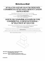
36" (91.4 CM) AND 48" (121.9 CM) DESIGNER
COMMERCIAL-STYLE WALL-MOUNT CANOPY
RANGE HOOD
(;_lllIl(?
For questions about features, operation/performance, parts, accessories or service, call: 1-800-422-1230
or visit our website at www.kitchenaid.com
In Canada, for assistance, installation and service, call: 1-800-807-6777
or visit our website at www.kitchenaid.ca
HO'I'IE DE CUISINIERE STYLISEE DE TYPE
COMMERCIAL, A MONTAGE MURAL -
36" (91,4 CM) ET 48" (121,9 CM)
Au Canada, pour assistance, installation ou service composez le 1-800-807-6777
ou visitez notre site web & www.kitchenaid.ca
Para obtener acceso al manual de uso y cuidado en espafiol, o para obtener informaci6n adicional acerca de su producto, visite:
www.kitchenaid.com.
Tenga listo su n0mero de modelo completo. Puede encontrar el n0mero de modelo y de serie dentro de la cavidad superior de la puerta.
Table of Contents/Table des matieres ............................................................................. 2
IMPORTANT: READ AND SAVE THESE INSTRUCTIONS.
FOR RESIDENTIAL USE ONLY.
IMPORTANT : LIRE ET CONSERVER CES INSTRUCTIONS.
POUR UTILISATION Rf=SIDENTIELLE UNIQUEMENT.
W10233970D

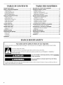
TABLEOF CONTENTS TABLE DES MATIERES
RANGE HOOD SAFETY ................................................................. 2
INSTALLATION REQUIREMENTS ................................................ 3
Tools and Parts ............................................................................ 3
Location Requirements ................................................................ 4
Venting Requirements .................................................................. 5
Electrical Requirements ............................................................... 6
INSTALLATION INSTRUCTIONS .................................................. 6
Prepare Location .......................................................................... 6
Install Range Hood ....................................................................... 8
Make Electrical Connection ......................................................... 8
Install Chimney Covers ................................................................ 9
Install Grease Filters ..................................................................... 9
Check Operation .......................................................................... 9
RANGE HOOD USE ...................................................................... 10
Range Hood Controls ................................................................ 10
RANGE HOOD CARE ................................................................... 11
Range Hood Lamps ................................................................... 11
Cleaning ...................................................................................... 11
WIRING DIAGRAM ....................................................................... 12
ASSISTANCE OR SERVICE ......................................................... 13
In the U.S.A................................................................................ 13
In Canada ................................................................................... 13
Accessories ................................................................................ 13
WAR RANTY .................................................................................. 14
SECURITE DE LA HOTTE DE CUlSINIERE ............................... 15
EXIGENCES D'INSTALLATION ................................................... 17
Outillage et pieces ...................................................................... 17
Exigences d'emplacement ......................................................... 17
Exigences concernant I'evacuation ........................................... 18
Specifications electriques .......................................................... 19
INSTRUCTIONS D'INSTALLATION ............................................. 20
Preparation de I'emplacement ................................................... 20
Installation de la hotte ................................................................ 21
Raccordement electrique ........................................................... 22
Installation du cache-cheminee ................................................. 22
Installation des filtres a graisse .................................................. 23
ContrGle du fonctionnement ...................................................... 23
UTILISATION DE LA HOTTE DE CUlSINIERE ........................... 23
Commandes de lahotte de cuisiniere ....................................... 23
ENTRETIEN DE LA HOTTE DE CUlSINIF:RE ............................. 24
Lampes de lahotte de cuisiniere ............................................... 24
Nettoyage ................................................................................... 25
SCHEMA DE C.&,BLAGE............................................................... 26
ASSISTANCE OU SERVICE ......................................................... 27
Accessoires ................................................................................ 27
GARANTIE ..................................................................................... 28
RANGE HOOD SAFETY
Your safety and the safety of others are very important.
We have provided many important safety messages in this manual and on your appliance. Always read and obey all safety
messages.
This is the safety alert symbol.
This symbol alerts you to potential hazards that can kill or hurt you and others.
All safety messages will follow the safety alert symbol and either the word "DANGER" or "WARNING."
These words mean:
You can be killed or seriously injured if you don't immediately
follow instructions.
You can be killed or seriously injured if you don't follow
instructions.
All safety messages will tell you what the potential hazard is, tell you how to reduce the chance of injury, and tell you what can
happen if the instructions are not followed.
2

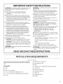
iMPORTANT SAFETY iNSTRUCTiONS
WARNING: TO REDUCE THE RISK OF FIRE, ELECTRIC
SHOCK, OR INJURY TO PERSONS, OBSERVE THE
FOLLOWING:
m Use this unit only in the manner intended by the
manufacturer. Ifyou have questions, contact the
manufacturer.
m Before servicing or cleaning the unit, switch power off at
service panel and lock the service disconnecting means to
prevent power from being switched on accidentally. When
the service disconnecting means cannot be locked,
securely fasten a prominent warning device, such as a tag,
to the service panel.
m Installation work and electrical wiring must be done by
qualified person(s) in accordance with all applicable codes
and standards, including fire-rated construction.
m Sufficient air is needed for proper combustion and
exhausting of gases through the flue (chimney) of fuel
burning equipment to prevent backdrafting. Follow the
heating equipment manufacturer's guideline and safety
standards such as those published by the National Fire
Protection Association (NFPA), the American Society for
Heating, Refrigeration and Air Conditioning Engineers
(ASHRAE), and the local code authorities.
m When cutting or drilling into wall or ceiling; do not damage
electrical wiring and other utilities.
m Ducted fans must always be vented outdoors.
CAUTION: For general ventilating use only. Do not use
to exhaust hazardous or explosive materials and vapors.
CAUTION: To reduce risk of fire and to properly exhaust
air, be sure to duct air outside - do not vent exhaust air into
spaces within walls or ceilings, attics or into crawl spaces,
or garages.
WARNING: TO REDUCE THE RISK OF FIRE, USE ONLY
METAL DUCTWORK.
WARNING: TO REDUCE THE RISK OF A RANGE TOP
GREASE FIRE:
m Never leave surface units unattended at high settings.
Boilovers cause smoking and greasy spillovers that may
ignite. Heat oils slowly on low or medium settings.
m Always turn hood ON when cooking at high heat or when
flambeing food (i.e. Crepes Suzette, Cherries Jubilee,
Peppercorn Beef Flamb6).
m Clean ventilating fans frequently. Grease should not be
allowed to accumulate on fan or filter.
m Use proper pan size. Always use cookware appropriate for
the size of the surface element.
WARNING: TO REDUCE THE RISK OF INJURY TO
PERSONS IN THE EVENT OF A RANGE TOP GREASE
FIRE, OBSERVE THE FOLLOWING: a
m SMOTHER FLAMES with a close fitting lid, cookie sheet, or
metal tray, then turn off the burner. BE CAREFUL TO
PREVENT BURNS. Ifthe flames do not go out
immediately, EVACUATE AND CALL THE FIRE
DEPARTMENT.
m NEVER PICK UP A FLAMING PAN - you may be burned.
m DO NOT USE WATER, including wet dishcloths or towels -
a violent steam explosion will result.
m Use an extinguisher ONLY if:
- You know you have a class ABC extinguisher, and you
already know how to operate it.
- The fire is small and contained in the area where it
started.
- The fire department is being called.
- You can fight the fire with your back to an exit.
aBased on "Kitchen Fire Safety Tips" published by NFPA.
= WARNING: To reduce the risk of fire or electrical shock,
do not use this fan with any solid-state speed control
device.
READ AND SAVE THESE iNSTRUCTiONS
INSTALLATION REQUIREMENTS
Gather the required tools and parts before starting installation.
Read and follow the instructions provided with any tools listed
here.
Tools needed
• Level
• Drill
• Drill 1W' (3 cm) drill bit
• 3/32"(2.4 mm) drill bit if installing into wood
• 5Ae"(7.9 mm) drill bit if installing optional backsplash kit
• Pencil
• Wire stripper or utility knife
• Tape measure or ruler
• Pliers
• Caulking gun and weatherproof caulking compound
• Vent clamps
• Jigsaw or keyhole saw
• Flat-blade screwdriver
• Metal snips
• Phillips screwdriver
• Scissors

Partsneeded
• Homepowersupplycable
• 1-1/2"(12.7mm)ULlistedorCSAapprovedstrainrelief
• 2ULlistedwireconnectors
• 1wallorroofcap
• Metalventsystem
• 2-250-wattmaxheatlampbulbs
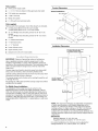
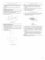
Product Dimensions
Vented Installations
147/8'' (37.8 cm) "/'_ _'_-
247/8-
Parts supplied
Remove parts from packages. Check that all parts are included.
• 3 metal grease filters for 36" (91.4 cm) models
4 metal grease filters for 48" (121.9 cm) models
• 10 - #10 Phillips head mounting screws for 36" (91.4 cm)
models
12 - #10 Phillips head mounting screws for 48" (121.9 cm)
models
• 4 - washer head screws
• 4- flat head screws
• 4-"L" brackets
• Lower chimney cover
• Upper chimney cover
• Damper (2 for 48" [121.9 cm] model)
IMPORTANT: Observe all governing codes and ordinances.
Have a qualified technician install the range hood. It is the
installer's responsibility to comply with installation clearances
specified on the model/serial rating plate. The model/serial rating
plate is located inside the range hood on the rear wall of the
range hood.
Canopy range hood location should be away from strong draft
areas, such as windows, doors and strong heating vents.
Cabinet opening dimensions that are shown must be used. Given
dimensions provide minimum clearance.
The canopy range hood is factory set for venting through the roof
or through the wall.
All openings in ceiling and wall where canopy range hood will be
installed must be sealed.
37"
211/4" (94,0 cm)
(54.0 cm) max,
77/8'' (20.0 cm)
/
25" (63,5 cm)
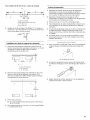
Installation Dimensions
36" (91.4 crn) or 48" (121.9 crn)
or cabinet opening width
(if installed between cabinets)
¢- -I
)
(
)
)
See Note*
18" (45.7 crn) rnin.
clearance upper
cabinet to countertop
For Mobile Home Installations
The installation of this range hood must conform to the
Manufactured Home Construction Safety Standards, Title 24
CFR, Part 328 (formerly the Federal Standard for Mobile Home
Construction and Safety, Title 24, HUD, Part 280) or when such
standard is not applicable, the standard for Manufactured Home
Installation 1982 (Manufactured Home Sites, Communities and
Setups) ANSI A225.1/NFPA 501A*, or latest edition, or with local
codes.
36" (91.4 crn)
countertop height
*NOTE: The range hood chimneys are adjustable and designed
to meet varying ceiling or soffit heights depending on the
distance "X" between the bottom of the range hood and the
cooking surface. For higher ceilings, a 39" (99.1 cm) Chimney
Extension Kit Part Number W10197714 (Stainless Steel), is
available from your dealer or an authorized parts distributor. The
chimney extension replaces the upper chimney shipped with the
range hood.
IMPORTANT:
Minimum distance "X": 30" (76.2 cm)
Suggested maximum distance "X": 36" (91.4 cm)
For vented installations, the chimneys can be adjusted for
ceilings between 8' 4W' (2.55 m) and 9' 3W' (2.83 m).

• Ventsystemmustterminatetotheoutdoors.
• Donotterminatetheventsysteminanatticorotherenclosed
area.
• Donotuse4"(10.2cm)laundry-typewallcaps.
• Usemetalventonly.Rigidmetalventisrecommended.
Plasticormetalfoilventisnotrecommended.
• Thelengthofventsystemandnumberofelbowsshouldbe
kepttoaminimumtoprovideefficientperformance.
For the most efficient and quiet operation:
• Use no more than three 90° elbows.
• Make sure there is a minimum of 24" (61.0 cm) of straight
vent between the elbows if more than 1 elbow is used.
• Do not install 2 elbows together.
• Use clamps to seal all joints in the vent system.
• The vent system must have a damper. If the roof or wall cap
has a damper, do not use the damper supplied with the range
hood.
• Use caulking to seal exterior wall or roof opening around the
cap.
• The size of the vent should be uniform.
Cold weather installations
An additional back draft damper should be installed to minimize
backward cold air flow and a thermal break should be installed to
minimize conduction of outside temperatures as part of the vent
system. The damper should be on the cold air side of the thermal
break.
The break should be as close as possible to where the vent
system enters the heated portion of the house.
Makeup air
Local building codes may require the use of makeup air systems
when using ventilation systems greater than specified CFM of air
movement. The specified CFM varies from locale to locale.
Consult your HVAC professional for specific requirements in your
area.
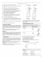
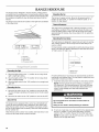
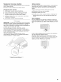
Roof Venting Wall Venting
A. Roof cap A. Wall cap
B. 6" (15.2 cm) B. 6" (15.2 cm)
round vent* round vent*
*The 48" (121.9 cm) range hood uses two 6" (15.2 cm) round
vents or transitions to 10" (25.4 cm) round vent using Part
Number 4396915.
Calculating Vent System Length
To calculate the length of the system you need, add the
equivalent feet (meters) for each vent piece used in the system.
Vent Piece Equivalent Length
45° elbow 2.5 ft
(0.8m)
90° elbow 5.0 ft
(1.5m)
Venting Methods
A 6" (15.2 cm) round vent system is needed for installation (not
included). The range hood exhaust opening is 6" (15.2 cm) round.
Two 6" (15.2 cm) round vent systems are needed for installation
on 48" (121.9 cm) models.
NOTE: Flexible vent is not recommended. Flexible vent creates
back pressure and air turbulence that greatly reduce
performance.
Vent system can terminate either through the roof or wall. To vent
through the wall, a 90° elbow is needed.
The maximum equivalent vent lengths are:
6" (15.2 cm) round vent - 35 ft (10.7 m)
7" (17.8 cm) round vent - 40 ft (12.2 m)
8" (20.3 cm) round vent - 50 ft (15.2 m)
9" (22.9 cm) and 10" (25.4 cm) round vents - 60 ft (18.3 m)
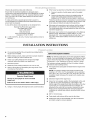
Example vent system
90°elbow <-- 6ft(1.8rn)_1 ....Wall cap
The following example falls within the maximum recommended
vent length.
1 - 90° elbow = 5.0 ft (1.5 m)
1 - wall cap = 0.0 ft (0.0 m)
8 ft (2.4 m) straight = 8.0 ft (2.4 m)
Length of system = 13.0 ft (3.9 m)

Observeallgoverningcodesandordinances.
Ensurethattheelectricalinstallationisadequateandin
conformancewithNationalElectricalCode,ANSI/NFPA70(latest
edition),orCSAStandardsC22.1-94,CanadianElectricalCode,
Part1andC22.2No.0-M91(latestedition)andalllocalcodes
andordinances.
Ifcodespermitandaseparategroundwireisused,itis
recommendedthataqualifiedelectriciandeterminethatthe
groundpathisadequate.
Acopyoftheabovecodestandardscanbeobtainedfrom:
NationalFireProtectionAssociation
OneBatterymarchPark
Quincy,MA02269
CSAInternational
8501EastPleasantValleyRoad
Cleveland,OH44131-5575
• A120Volt,60Hz.,AConly,15-amp,fusedelectricalcircuitis
required.
• Ifthehousehasaluminumwiringfollowtheprocedurebelow:
1. Connectasectionofsolidcopperwiretothepigtail
leads.
2. Connectthealuminumwiringtotheaddedsectionof
copperwireusingspecialconnectorsand/ortools
designedandULlistedforjoiningcoppertoaluminum.
Followtheelectricalconnectormanufacturer'srecommended
procedure.Aluminum/copperconnectionmustconformwith
localcodesandindustryacceptedwiringpractices.
• Wiresizesandconnectionsmustconformwiththeratingof
theapplianceasspecifiedonthemodel/serialratingplate.
Themodel/serialplateislocatedbehindthefilterontherear
walloftherangehood.
• WiresizesmustconformtotherequirementsoftheNational
ElectricalCode,ANSI/NFPA70(latestedition),orCSA
StandardsC22.1-94,CanadianElectricalCode,Part1and
C22.2No.0-M91(latestedition)andalllocalcodesand
ordinances.
INSTALLATION INSTRUCTIONS
• It is recommended that the vent system be installed before
range hood is installed.
• Before making cutouts, make sure there is proper clearance
within the ceiling or wall for exhaust vent.
• Check your ceiling height and the range hood height
maximum before you select your range hood.
1. Disconnect power.
2. Determine which venting method to use: roof or wall.
3. Select a flat surface for assembling the range hood. Place
covering over that surface.
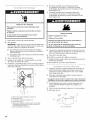
Excessive Weight Hazard
Use two or more people to move and install
range hood.
Failure to do so can result in back or other injury.
4. Using 2 or more people, lift range hood onto covered surface.
Optional Backsplash Installation
NOTE: The following instructions are for the backsplash without
shelves. Ifyou are installing the Backsplash with Shelves for Heat
Lamps, follow the instructions included with that product. (See
"Accessories" in the "Assistance or Service" section to order.)
The hardware package supplied with the kit includes 4 plastic
wall anchors and mounting screws.
• The height of the backsplash will determine the height of the
range hood.
NOTE: The minimum height of the range hood above the
cooktop is 30" (76.2 cm). The backsplash can be extended
from 1923/32'' (50.1 cm) to 39" (99.1 cm). As the 30" (76.2 cm)
installation height increases, the range hood's capture area
decreases.
Determine height of the range hood.
Using 2 or more people, position the backsplash on the wall
so that the top of the backsplash is at the height of the
bottom edge of the range hood. Mark the location of the four
corner holes. It is recommended that the backsplash be
attached to the wall at all four corners. However, the lower
flange can be secured between the wall and backspash,
countertop or cabinet base without using the bottom corner
screws.
• Drill 5/16"(8 mm) holes.
• Push plastic wall anchors all the way into the holes.
• Position the holes in the backsplash over the wall anchors
and attach using the screws supplied.
6

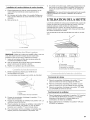
Range Hood Mounting Screws Installation
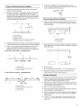
1. Determine and mark the centerline on the wall where the
range hood will be installed.
2. Based on the ceiling or soffit height, determine the distance
"X" (30" [76.2 cm] min., suggested 36" [91.4 cm] max.)
needed between the cooking surface and the bottom of the
range hood. To this distance, add 19" (48.3 cm) and draw a
horizontal line (A) about 24" (61.0 cm) long centered on the
vertical centerline (B) at this distance.
A\
c\
B\ x + 19" (48.3 crn)
;
I
A. Horizontal fine
B. Vertical centerline
C. Cooking surface
D. Distance "X" (30" [76.2 cm] min., suggested
36" [91.4 cm] max.) + 19" (48.3 cm)
3. Following the illustrations in Step 4, mark points on each side
of the horizontal line as measured from the vertical centerline.
4. Drill 3/32"(2.4 mm) pilot holes for installation into wood. The
screws provided for mounting this range hood must be
fastened into solid wood. Do not fasten only into sheet rock.
For 36" (91.4 cm) models - 2 mounting holes
A
B
I I
C
A. Horizontal fine
B. Vertical centerline of range hood
C. 4_" (11.6 cm)
For 48" (121.9 cm) model) - 4 mounting holes
i D .... D i
A. Horizontal fine
B. Vertical centerline of range hood
C. 1_" (3.3 cm)
D. 9 _" (23.2 cm)
5. Install the #10 Phillips head mounting screws. Leave a
1/4"(6.4 mm) gap between the wall and the back of the screw
head to slide range hood into place.
(6.4rnrn) _
Chimney Support Bracket Installation
1.
2.
Place two of the chimney brackets against the wall so that
their top edges are 1Ae"(2.0 mm) from the ceiling or soffit and
level. Mark holes.
C B
I
A .........................I
A. Vertical centerline
B. _" (1.6 mm)
C. 11" (27.9 cm)
Place the other two chimney brackets on the wall so that their
lower edges are 161/16'' (40.8 cm) from the ceiling or soffit and
level. Mark holes.
©
o
° l
161/1o''
(40.8 rnrn)
oil [
3. Drill pilot holes.
• If installing into wood, drill 4 - 3/32"(2.4 mm) pilot holes.
4. Attach each bracket to the wall with a #10 Phillips head
mounting screw. Tighten screws securely.
Complete Preparation
1. Determine and make all necessary cuts in the wall for the vent
system. Install the vent system before installing the range
hood. See the "Venting Requirements" section.
2. Determine the location where the power supply cable will be
run through the wall. Be sure that the location will be covered
by the chimney of the range hood.
3. Drill a 11/4"(3.2 cm) hole at this location.
4. Pull enough power supply cable through the wall to allow for
easy connection to the terminal box.
5. If roof or wall cap does not have a damper, attach damper to
exhaust openings on top of the range hood using 2 Phillips
head screws.
6. If the 48" (121.9 cm) range hood is to be connected to the
10" (25.4 cm) round vent system, install the vent transition
piece now.

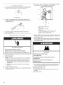
1.
2.
3.
1.
2.
Use a flat-blade screwdriver and tighten the 2 leveling screws
located close to the range hood mounting brackets.
A. Leveling screw
Using 2 or more people, lift the range hood and place the
mounting hood brackets over the mounting screws. Securely
tighten the screws.
Level the range hood. Adjust the 2 leveling screws (see
Step 1)as needed.
%,. I R:I, _¢ iI
Electrical Shock Hazard
Disconnect power before servicing.
Replace all parts and panels before operating.
Failure to do so can result in death or electrical shock.
Disconnect power.
Remove the filters.
NOTE: Use 2 hands to remove the filters, one to pull and turn
the knob, the other to hold the filter so that it doesn't fall.
Pull knob forward (toward the front of the range hood)
while turning the knob counterclockwise to release the
locking lever.
Slide the filter down and away from the front retaining
channel.
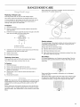
3. Remove terminal box cover.
4. Install a UL listed or CSA approved V2"strain relief in the hole
on top of the canopy.
5.
Run 3 wires, black, white, green or bare through strain relief,
into terminal box. Use caulking to seal openings.
................E
A. Home power supply cable
B. Black wires
C. UL listed wire connectors
D. White wires
E. Green (or bare) ground wire from home power
supply connected to green ground screw
F. Range hood power supply cable
6. Use UL listed wire connectors and connect the 3 black wires
(B) together (2 wires from the range hood and 1 wire from the
home supply cable).
7. Use UL listed wire connectors and connect the 3 white wires
(D) together (2 wires from the range hood and 1 wire from the
home supply cable).
!
Fire Hazard
Electrically ground the blower.
Use copper wire.
Connect ground wire to green ground screw in
terminal box.
Falure to do so can result in death, fire, or
electrical shock.
8. Connect green (or bare) ground wire from home power supply
to the unused green ground screw (E) in the terminal box.
9. Tighten strain relief screws.
10. Install terminal box cover.
11. Check all light bulbs to make sure they are secure in their
sockets.
12. Reconnect power.
8

1. Install damper on top of the exhaust opening. Check that the
damper opens freely. On 48" (121.9 cm) models, install
2 dampers.
2. Connect the vent system and seal all connections with
clamps.
Install Upper Chimney Cover
1. Slightly spread the sides of the cover apart and hook them
behind the chimney mounting brackets.
2. Attach the cover to the brackets with 4 flat head screws.
3. Securely tighten screws.
A
A. 4 flat head screws
Install Lower Chimney Cover
1. Slightly spread the sides of the cover apart and hook them
behind the upper chimney.
2. From inside the range hood, use the 4 Phillips washer head
screws to attach the lower chimney cover to the canopy of
the range hood.
3. Securely tighten screws.
NOTE: Use 2 hands to install filter, one to pull and turn the knob,
the other to hold the filter in place so that it doesn't fall.
1. Insert back edge of filter into rear channel of the filter
opening.
2. Pull out on knob and turn counterclockwise, position front
edge into place and release knob.
3. Repeat for remaining filters.
1=
2.
Check operation of the range hood by turning on the power.
The range hood controls are located on the right-hand
underside of the range hood.
C
A. Controls
B. Filters
C. Heat lamp switch
3. Move the light switch to "1" position. The light should turn on.
4. Move fan switch to "On" position. The fan should operate.
5. Move the fan speed switch to "1" position for low speed, "2"
position for medium speed, or "3" position for high speed.
6. Move fan and light switches to "Off" position to turn fan and
light off.
7. If range hood does not operate, check to see whether a
circuit breaker has tripped or a household fuse has blown.
Disconnect power supply and check that the wiring is
correct.
NOTE: To get the most efficient use from your new range hood,
read the "Range Hood Use" section.
A. 4 washer head screws

RANGE HOOD USE
The range hood is designed to remove smoke, cooking vapors
and odors from the cooktop area. For best results, start the range
hood before cooking and allow it to operate several minutes after
the cooking is complete to clear all smoke and odors from the
kitchen.
The range hood controls are located on the right-hand underside
of the range hood.
Adjusting the fan
The fan has 3 speed controls. Move the fan speed switch to "1"
position for low speed, "2" position for medium speed, or "3"
position for high speed.
Thermal Protector
The range hood is equipped with a thermal protector to avoid
overheating conditions. If the range hood shuts off while in use,
move fan slider switch to Off to turn off the range hood. Wait
approximately 60 minutes, then move slider to On to restart the
range hood.
Operating the heat lamp
The heat lamps are designed to keep food warm prior to serving.
The cooktop surface is too far away from the heat lamp to be
used as a shelf.
For best results, install a metal shelf to hold the food closer to the
lamps. The optimum distance between the shelf and the hood is
12" (30.5 cm) to 15" (38.1 cm).
B C D
A. Controls
B. Light switch
C. Fan switch
D. Fan speed switch
tQ
Operating the light
1. Move the light switch to the "1" position to turn range hood
light to night light setting.
2. Move the light switch to the "2" position to turn range hood
light to full light setting.
3. Move the light switch to the "Off" position to turn range hood
light OFE
Operating the fan
1. Move the fan switch to the "On" position to turn the fan ON.
The fan will begin operating at the speed set on the fan speed
switch.
2. Move the fan switch to the "Off" position to turn the fan OFR
Auto On Fan
The range hood is equipped with a sensor to automatically turn
on the fan when excessive heat is detected in the control area.
When the fan switch is in the "Off" position, this sensor will turn
the fan to high speed when necessary. When the heat decreases,
the fan will turn off.
When the fan switch is in the "On" position, the heat sensor is not
active and the range hood functions normally.
12" (30.5 cm) Minimum
15" (38.1 cm) Maximum
A. Range hood
B. Metal shelf
For best performance, food should be placed directly under the
heat lamps, not between them. You may need to adjust your food
placement to match your needs.
1. Install heat lamp bulbs (not included) into heat lamp sockets.
NOTE: Heat lamp bulbs should be rated to a maximum of
250 watts each. For best performance, 250 watt, R40 type,
red heat lamp bulbs are recommended. Bulb performance
varies. Lower wattage and clear bulbs decrease the
performance.
Food Poisoning Hazard
Do not let food sit for more than one hour before or
after cooking.
Doing so can result in food poisoning or sickness.
2.
To turn on a heat lamp, move the switch for the desired lamp
into the "1" position. To turn off the heat lamp, move the
switch to the "O" position. Repeat for the other heat lamp.
NOTE: The left switch is for the left heat lamp, and the right
switch is for the right heat lamp.
10

RANGE HOOD CARE
.... .....[
Replacing a Halogen Lamp
This range hood uses 12-volt, 20-watt halogen lamps.
Turn off the range hood and allow the halogen lamps to cool.
To avoid damage or decreasing the life of the new bulb, do not
touch bulb with bare fingers. Replace bulb using tissue or
wearing cotton gloves to handle bulb.
To Replace:
1. Disconnect power.
2. Remove 2 screws from the circular metal trim around the
lamp assembly.
3. Pull the trim and lamp assembly down far enough so that the
lamp can be pulled out of the socket clips.
A. Remove 2 screws.
B. Pull trim with lamp assembly down.
4. Insert the new lamp into the socket clips and push the lamp
assembly back up into the range hood.
5. Replace the screws.
6. Reconnect the power.
Replacing a Heat Lamp
This range hood uses two 250 watt maximum heat lamps.
Turn off the heat lamps and allow them to cool.
To Replace:
1. Disconnect power.
2. Remove the heat lamp bulb from its socket.
3. Replace the heat lamp bulb with the same type bulb and
tighten it in its socket.
4. Repeat steps 2 and 3 with the other heat lamp bulb if
necessary.
5. Reconnect the power.
NOTE: The range hood control is equipped with a sensor that will
automatically turn the fan on high speed when excessive heat is
detected in the control area and the fan switch is in the "Off"
position.
Before cleaning or servicing the range hood, move the fan auto-
on switch to the "0" position (sensor Off). The switch is located
behind the filters. See "Metal Filters" in this section to remove the
filters.
When cleaning or servicing is complete, move the fan auto-on
switch to the "1" position (sensor On).
/
A. Fan auto-on switch (shown in Off position)
Exterior surfaces:
To avoid damage to the exterior surface, do not use steel wool or
soap-filled scouring pads. Rub in direction of the grain line to
avoid scratching the surface.
Always wipe dry to avoid water marks.
• Stainless Steel Cleaner and Polish.
• Mild liquid detergent and water.
• Wipe with damp soft cloth or nonabrasive sponge, then rinse
with clean water and wipe dry.
Metal Filters:
For vented installations, use 2 hands to remove filters. Turn the
knob to the left (counterclockwise) to release filter. Repeat with
other filter.
Wash metal filters as needed in dishwasher or hot detergent
solution to clean.
Reinstall the filter by placing the back edge in the channel at rear
of range hood. Push filter into place, turn the knob to the right
(clockwise) to attach to range hood. Repeat with other filter.
11

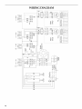
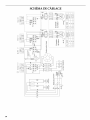
WIRING DIAGRAM
co
co
o4
co
co
o4
o
®
2_
o
÷
,,Bu_
F............. ',-w _t _%
I L Ico _1 DR 'Drk_
-,---BR-_
L I °4 _1
___ _@ @-
co
I
GY _ BR
BR
W
CO J
_ BK _,
<I:CO
W
R R
V V
BU
n
BU
R
W
BK
W
BK
BK
W
W
12

ASSISTANCE OR SERVICE
When calling for assistance or service, please know the purchase
date and the complete model and serial number of your
appliance. This information will help us to better respond to your
request.
If you need replacement parts
If you need to order replacement parts, we recommend that you
use only factory specified parts. Factory specified parts will fit
right and work right because they are made with the same
precision used to build every new appliance. To locate factory
specified replacement parts in your area, call us or your nearest
designated service center.
ii] iI'-_:_ I _;;(i!!I
Call the KitchenAid Customer eXperience Center toll free:
1-800-422-1230.
Our consultants provide assistance with:
• Features and specifications on our full line of appliances.
• Installation information.
• Use and maintenance procedures.
• Accessory and repair parts sales.
• Specialized customer assistance (Spanish speaking, hearing
impaired, limited vision, etc.).
• Referrals to local dealers, repair parts distributors and service
companies. KitchenAid designated service technicians are
trained to fulfill the product warranty and provide after-
warranty service, anywhere in the United States.
To locate the KitchenAid designated service company in your
area, you can also look in your telephone directory Yellow
Pages.
For further assistance
If you need further assistance, you can write to KitchenAid with
any questions or concerns at:
KitchenAid Brand Home Appliances
Customer eXperience Center
553 Benson Road
Benton Harbor, MI 49022-2692
Call the KitchenAid Canada Customer eXperience Centre toll
free: 1-800-807-6777.
Our consultants provide assistance with:
• Features and specifications on our full line of appliances.
• Use and maintenance procedures.
• Accessory and repair parts sales.
• Referrals to local dealers, repair parts distributors and service
companies. KitchenAid Canada designated service
technicians are trained to fulfill the product warranty and
provide after-warranty service, anywhere in Canada.
For further assistance
If you need further assistance, you can write to KitchenAid
Canada with any questions or concerns at:
Customer eXperience Centre
KitchenAid Canada
1901 Minnesota Court
Mississauga, Ontario L5N 3A7
Please include a daytime phone number inyour correspondence.
Chimney Extension Kit
Order Part Number W10197714 Stainless Steel
Backsplash Kit (for use without Heat Lamp)
Order Part Number 8284756 for 36" (91.4 cm) model
Order Part Number 8284755 for 48" (121.9 cm) model
Backsplash Kit (for use with Heat Lamp)
Order Part Number W10225949 for 36" (91.4 cm) model
Order Part Number W10225948 for 48" (121.9 cm) model
Please include a daytime phone number in your correspondence.
13

KITCHENAID ®VENTILATION WARRANTY
LIM ITED WARRANTY
For one year from the date of purchase, when this major appliance is operated and maintained according to instructions attached to or
furnished with the product, KitchenAid brand of Whirlpool Corporation or Whirlpool Canada LP (hereafter "KitchenAid") will pay for
Factory Specified Parts and repair labor to correct defects in materials or workmanship. Service must be provided by a KitchenAid
designated service company. This limited warranty is valid only in the United States or Canada and applies only when the major
appliance is used in the country in which it was purchased. Outside the 50 United States and Canada, this limited warranty does not
apply. Proof of original purchase date is required to obtain service under this limited warranty.
ITEMS EXCLUDED FROM WARRANTY
This limited warranty does not cover:
1. Service calls to correct the installation of your major appliance, to instruct you on how to use your major appliance, to replace or
repair house fuses, or to correct house wiring or plumbing.
2. Service calls to repair or replace appliance light bulbs, air filters or water filters. Consumable parts are excluded from warranty
coverage.
3. Repairs when your major appliance is used for other than normal, single-family household use or when it is used in a manner that is
contrary to published user or operator instructions and/or installation instructions.
4. Damage resulting from accident, alteration, misuse, abuse, fire, flood, acts of God, improper installation, installation not in
accordance with electrical or plumbing codes, or use of consumables or cleaning products not approved by KitchenAid.
5. Cosmetic damage, including scratches, dents, chips or other damage to the finish of your major appliance, unless such damage
results from defects in materials or workmanship and is reported to KitchenAid within 30 days from the date of purchase.
6. Costs associated with the removal from your home of your major appliance for repairs. This major appliance is designed to be
repaired in the home and only in-home service is covered by this warranty.
7. Repairs to parts or systems resulting from unauthorized modifications made to the appliance.
8. Expenses for travel and transportation for product service if your major appliance is located in a remote area where service by an
authorized KitchenAid servicer is not available.
9. The removal and reinstallation of your major appliance if it is installed in an inaccessible location or is not installed in accordance
with published installation instructions.
10. Major appliances with original model/serial numbers that have been removed, altered or cannot be easily determined. This warranty
is void if the factory applied serial number has been altered or removed from your major appliance.
The cost of repair or replacement under these excluded circumstances shall be borne by the customer.
DISCLAIMER OF IMPLIED WARRANTIES; LIMITATION OF REMEDIES
CUSTOMER'S SOLE AND EXCLUSIVE REMEDY UNDER THIS LIMITED WARRANTY SHALL BE PRODUCT REPAIR AS PROVIDED
HEREIN. IMPLIED WARRANTIES, INCLUDING WARRANTIES OF MERCHANTABILITY OR FITNESS FOR A PARTICULAR PURPOSE,
ARE LIMITED TO ONE YEAR OR THE SHORTEST PERIOD ALLOWED BY LAW. KITCHENAID SHALL NOT BE LIABLE FOR
INCIDENTAL OR CONSEQUENTIAL DAMAGES. SOME STATES AND PROVINCES DO NOT ALLOW THE EXCLUSION OR LIMITATION
OF INCIDENTAL OR CONSEQUENTIAL DAMAGES, OR LIMITATIONS ON THE DURATION OF IMPLIED WARRANTIES OF
MERCHANTABILITY OR FITNESS, SO THESE EXCLUSIONS OR LIMITATIONS MAY NOT APPLY TO YOU. THIS WARRANTY GIVES
YOU SPECIFIC LEGAL RIGHTS, AND YOU MAY ALSO HAVE OTHER RIGHTS WHICH VARY FROM STATE TO STATE OR PROVINCE
TO PROVINCE.
If outside the 50 United States and Canada, contact your authorized KitchenAid dealer to determine if another warranty applies.
If you need service, first see the "Troubleshooting" section of the Use & Care Guide. After checking "Troubleshooting," you may find
additional help by checking the "Assistance or Service" section or by calling KitchenAid. In the U.S.A., call 1-800-422-1230. In Canada,
call 1-800-807-6777. 9/07
Keep this book and your sales slip together for future
reference. You must provide proof of purchase or installation
date for in-warranty service.
Write down the following information about your major appliance
to better help you obtain assistance or service if you ever need it.
You will need to know your complete model number and serial
number. You can find this information on the model and serial
number label located on the product.
Dealer name
Address
Phone number
Model number
Serial number
Purchase date
14

p p
SECURITE DE LA HOTTE DE CUISINIERE
Votre securit6 et celle des autres est tres importante.
Nous donnons de nombreux messages de s6curit6 importants dans ce manuel et sur votre appareil m6nager. Assurez-vous de
toujours lire tousles messages de s6curit6 et de vous y conformer.
Voici le symbole d'alerte de s6curit&
Ce symbole d'alerte de s6curit6 vous signale les dangers potentiels de d6c6s et de blessures graves & vous
et & d'autres.
Tous les messages de s6curit6 suivront le symbole d'alerte de s6curit6 et le mot "DANGER" ou
"AVERTISSEMENT". Ces mots signifient •
Risque possible de d6ces ou de blessure grave si vous ne
suivez pas imm6diatement les instructions.
Risque possible de d6cbs ou de blessure grave si vous
ne suivez pas les instructions.
Tous les messages de s6curit6 vous diront quel est le danger potentiel et vous disent comment r6duire le risque de blessure et
ce qui peut se produire en cas de non-respect des instructions.
15

llVIPORTANTES iNSTRUCTiONS DE SI CURITI
AVERTISSEMENT : POUR REDUIRE LE RISQUE
D'INCENDIE, CHOC ¢:LECTRIQUE OU DOMMAGES
CORPORELS, RESPECTER LES INSTRUCTIONS
SUIVANTES :
m Utiliser cet appareil uniquement dans les applications
envisag6es par le fabricant. Pour toute question, contacter
le fabricant.
m Avant d'entreprendre un travail d'entretien ou de nettoyage,
interrompre I'alimentation de la hotte au niveau du tableau
de disjoncteurs, et verrouiller le tableau de disjoncteurs
pour emp6cher tout r6tablissement accidentel de
I'alimentation du circuit. Lorsqu'il n'est pas possible de
verrouiller le tableau de disjoncteurs, placer sur letableau
de disjoncteurs une 6tiquette d'avertissement pro6minente
interdisant le r6tablissement de I'alimentation.
m Tout travail d'installation ou c&blage 61ectrique doit 6tre
r6alis6 par une personne qualifi6e, dans le respect des
prescriptions de tousles codes et normes applicables, y
compris les codes du b&timent et de protection contre les
incendies.
m Une source d'air de d6bit suffisant est n6cessaire pour le
fonctionnement correct de tout appareil & gaz (combustion
et 6vacuation des gaz & combustion par la chemin6e), pour
qu'il n'y ait pas de reflux des gaz de combustion. Respecter
les directives du fabricant de 1'6quipement de chauffage et
les prescriptions des normes de s6curit6 - comme celles
publi6es par la National Fire Protection Association (NFPA)
et I'American Society for Heating, Refrigeration and Air
Conditioning Engineers (ASHRAE), et les prescriptions des
autorit6s r6glementaires locales.
m Lors d'op6rations de d6coupage et de per£:age dans un mur
ou un plafond, veiller & ne pas endommager les c&blages
61ectriques ou canalisations qui peuvent s'y trouver.
m Les ventilateurs d'6vacuation doivent toujours d6charger
I'air & I'ext6rieur.
IVllSE EN GARDE : Cet appareil est con£:u uniquement
pour la ventilation g6n6rale. Ne pas I'utiliser pour I'extraction
de mati_res ou vapeurs dangereuses ou explosives.
MISE EN GARDE : Pour minimiser le risque d'incendie
et 6vacuer ad6quatement les gaz, veiller & acheminer I'air
aspir6 par un conduit jusqu'& I'ext6rieur - ne pas d6charger
I'air aspir6 dans un espace vide du b&timent comme une
cavit6 murale, un plafond, un grenier, un vide sanitaire ou
un garage.
AVERTISSEMENT : POUR R¢:DUIRE LE RISQUE
D'INCENDIE, UTILISER UNIQUEMENT DES CONDUITS
MI2TALLIQUES.
AVERTISSEIVIENT : POUR MINIMISER LE RISQUE
D'UN FEU DE GRAISSE SUR LA CUISINIERE :
=1Ne jamais laisser un 616ment de surface fonctionner &
puissance de chauffage maximale sans surveillance. Un
renversement/d6bordement de mati_re graisseuse pourrait
provoquer une inflammation et la g6n6ration de fum6e.
Utiliser une puissance de chauffage moyenne ou basse
pour le chauffage d'huile.
=1Veiller &toujours faire fonctionner le ventilateur de la hotte
Iors de la cuisson avec une puissance de chauffage 61ev6e
ou Iors de la cuisson d'un mets & flamber (& savoir cr6pes
Suzette, cerise jubil6e, steak au poivre flamb6).
=1Nettoyer fr6quemment les ventilateurs d'extraction. Veiller &
ne pas laisser la graisse s'accumuler sur les surfaces du
ventilateur ou des filtres.
=1Utiliser toujours un ustensile de taille appropri6e. Utiliser
toujours un ustensile adapt6 & la taille de 1'616ment
chauffant.
AVERTISSEMENT : POUR REDUIRE LE RISQUE DE
DOMMAGES CORPORELS APRF:S LE DECLENCHEMENT
D'UN FEU DE GRAISSE SUR LA CUISINICRE, APPLIQUER
LES RECOMMANDATIONS SUIVANTES :a
=1Placer sur le r6cipient un couvercle bien ajust6, une t61e&
biscuits ou un plateau m6tallique POUR ETOUFFER LES
FLAMMES, puis 6teindre le brOleur. VEILLER ,&.t2VITER
LES BRULURES. Si les flammes ne s'6teignent pas
imm6diatement, ¢:VACUER LA PIECE ET APPELER LES
POMPIERS.
=1NE JAMAIS PRENDRE EN MAIN UN RC:CIPIENT
ENFLAMME - vous risquez de vous brQler.
=1NE PAS UTILISER D'EAU, ni un torchon humide - ceci
pourrait provoquer une explosion de vapeur brOlante.
=1Utiliser un extincteur SEULEMENT si :
- II s'agit d'un extincteur de classe ABC, dont on connait le
fonctionnement.
- II s'agit d'un petit feu encore limit6 &I'endroit oQ il s'est
d6clar6.
- Les pompiers ont 6t6 contact6s.
- II est possible de garder le dos orient6 vers une sortie
pendant I'op6ration de lutte contre le feu.
aRecommandations tir6es des conseils de s6curit6 en cas
d'incendie de cuisine publi6s par la NFPA.
m AVERTISSEMENT : Pour r6duire le risque d'incendie
ou de choc 61ectrique, ne pas utiliser ce ventilateur avec un
quelconque dispositif de r6glage de la vitesse &semi-
conducteurs.
LIRE ET CONSERVER CES iNSTRUCTiONS
16

EXIGENCES D'INSTALLATION
Rassembler les outils et pieces necessaires avant de commencer
I'installation. Lire et suivre les instructions fournies avec les outils
indiqu6s ici.
Outils n6cessaires
• Niveau
• Perceuse
• Foret de 11¼"(3 cm)
• Foret de 3/32"(2,4 mm) en cas d'installation dans du bois.
• Foret de %e" (7,9 mm)) en cas d'installation d'un ensemble de
dosseret facultatif.
• Crayon
• Pince & denuder ou couteau utilitaire
• Metre-ruban ou regle
• Pince
• Pistolet & calfeutrage et compose de calfeutrage resistant
aux intemperies
• Brides de serrage pour conduit d'evacuation
• Scie sauteuse ou scie &guichet
• Tournevis &lame plate
• Cisaille de ferblantier
• Tournevis Phillips
• Ciseaux
Pi6ces n6cessaires
• Cordon d'alimentation electrique du domicile
• 1 serre-c&ble de 1/2"(12,7 mm) (homologation UL ou CSA)
• 2 connecteurs de ills homologues UL
• Bouche de decharge murale ou par le toit
• Circuit d'evacuation metallique
• 2 ampoules de lampes chauffantes de 250 W maximum
Pi_ces fournies
Retirer les pieces des emballages. Verifier que toutes les pieces
sont presentes.
• 3 filtres &graisse metalliques, pour modele de 36" (91,4 cm)
4 filtres a graisse metalliques, pour modele de 48" (121,9 cm)
• 10 vis de montage Phillips n° 10, pour modele de 36"
(91,4 cm)
12 vis de montage Phillips n° 10, pour modele de 48"
(121,9 cm)
4 vis rondelle
4 visa t_te plate
4 brides en "L"
Section inferieure du cache-cheminee
Section superieure du cache-cheminee
Clapet (2 pour modele de 48" [121,9 cm])
IMPORTANT : Observer les dispositions de tousles codes et
reglements en vigueur.
Confier I'installation de la hotte & un technicien qualifi& C'est &
I'installateur qu'incombe la responsabilite de respecter les
distances de separation specifiees sur la plaque signaletique de
I'appareil. La plaque signaletique est situee a I'interieur de la
hotte, sur la paroi arriere.
On doit toujours installer la hotte a distance des sources de
courant d'air (fen_tres, portes et bouches de chauffage).
Respecter les dimensions indiquees pour les ouvertures
decouper dans les placards; ces dimensions tiennent compte
des valeurs minimales des degagements de separation.
La hotte est configuree a I'usine pour la decharge a travers le toit
ou un mur.
Assurer I'etancheite au niveau de chaque ouverture decoupee
dans le plafond ou lemur pour I'installation de la hotte de
CUlSlnlere.
Installation dans une r_sidence mobile
L'installation de cette hotte doit satisfaire aux exigences de la
norme Manufactured Home Construction Safety Standards, Titre
24 CFR, partie 328 (anciennement Federal Standard for Mobile
Home Construction and Safety, titre 24, HUD, partie 280); Iorsque
cette norme n'est pas applicable, I'installation doit satisfaire aux
criteres de la plus recente edition de la norme Manufactured
Home Installation 1982 (Manufactured Home Sites, Communities
and Setups) ANSI A225.1/NFPA 501A*, ou des codes et
reglements Iocaux.
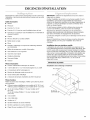
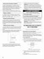
Dimensions du produit
Installations avec d_charge a I'ext_rieur
247/8" (63,2
[
37"
(94,0 cm)
17

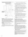
Dimensions & respecter Iors de I'installation
18" (45,7 cm) rnin.
d_gag.
placard superieur
et plan de travail
36" (91,4 cm), ou 48" (121,9 crn)
ou largeur de rouverture du placard
(en cas d'installation entre des placards)
/
/
36" (91,4 crn)
hauteur du plan
de travail
Voir la
remarque*
*REMARQUE : La cheminee de la hotte est reglable; on peut
I'ajuster en fonction de la hauteur disponible sous plafond ou
soffite, et selon la distance "X" entre le bas de la hotte et la
surface de cuisson. Pour des hauteurs sous plafond plus
elev6es, un ensemble d'extension de cheminee de
39" (99,1 cm), piece n° W10197714 (acier inoxydable),
est disponible chez votre marchand ou chez un distributeur de
pieces autoris& L'extension de cheminee remplace la section
superieure de cheminee fournie avec la hotte.
IMPORTANT :
Valeur minimale de la distance "X" : 30" (76,2 cm)
Valeur maximale sugger6e pour la distance "X" :
36" (91,4 cm)
Pour les installations avec decharge & I'exterieur, on peut ajuster
la cheminee pour une hauteur sous plafond de 8' 4W' (2,55 m)
9' 3W' (2,83 m).
• Le systeme d'evacuation doit decharger I'air a I'exterieur.
• Ne pas terminer le systeme d'evacuation dans un grenier ou
dans un autre espace ferme.
• Ne pas utiliser une bouche de decharge murale de
4" (10,2 cm) normalement utilisee pour un equipement de
buanderie.
• Utiliser un conduit d'evacuation metallique uniquement. Un
conduit en metal rigide est recommand& L'emploi d'un
conduit de plastique ou en aluminium n'est pas recommand&
• La Iongueur du systeme d'evacuation et le nombre de coudes
doit _tre reduit au minimum pour fournir la meilleure
performance.
Pour un fonctionnement efficace et silencieux :
• Ne pas utiliser plus de trois coudes a 90°.
• Veiller & ce qu'il y ait une section droite de conduit de
24" (61,0 cm) ou plus entre deux coudes, si on doit utiliser
plus d'un coude.
• Ne pas installer 2 coudes ensemble.
• Au niveau de chaque jointure du systeme d'evacuation,
assurer I'etanch6it6 avec les brides de serrage pour conduit.
• Le systeme d'evacuation doit comporter un clapet. Si la
bouche de decharge murale ou par le toit comporte un
clapet, ne pas utiliser le clapet fourni avec la hotte de
cuisiniere.
• Autour de la bouche de decharge a I'exterieur (par le mur ou
par le toit), assurer I'etanch6it6 avec un produit de
calfeutrage.
• La taille du conduit doit _tre uniforme.
Installations pour r_gions & climat froid
On doit installer un clapet anti-reflux additionnel _ I'arriere pour
minimiser le reflux d'air froid, et incorporer un element d'isolation
thermique pour minimiser la conduction de chaleur par
I'intermediaire du systeme d'evacuation. Le clapet anti-reflux doit
_tre place du c6te air froid par rapport & I'element d'isolation
thermique.
L'element d'isolation thermique doit _tre aussi proche que
possible de I'endroit oQ le systeme d'evacuation s'introduit dans
la partie chauffee de la maison.
Air d'appoint
Les codes de b&timent Iocaux peuvent exiger I'emploi d'un
systeme d'appoint d'air Iors de I'emploi d'un ventilateur
d'extraction dont la capacite d'aspiration est superieure & un
debit (pieds cubes par minute) specifi& Le debit specifie, en
pieds cubes par minute, est variable d'une juridiction & une autre.
Consulter un professionnel des installations de chauffage/
ventilation/climatisation au sujet des exigences specifiques
applicables dans la juridiction locale.
M_thodes d'_vacuation
Un circuit d'evacuation de conduits ronds de 6" (15,2 cm) est
necessaire pour I'installation (non fourni). La hotte comporte une
ouverture de sortie de diametre 6" (15,2 cm). Deux circuits
d'evacuation ronds de 6" (15,2 cm) sont necessaires pour une
installation sur des modeles de 48" (121,9 cm).
REMARQUE : On deconseille I'emploi d'un conduit flexible. Un
conduit flexible peut causer une retro-pression et des
turbulences de I'air, ce qui reduit considerablement la
performance.
18

La sortie a I'exterieur du circuit d'evacuation peut se faire
travers le toit ou & travers un mur. Pour la sortie a travers un mur,
I'utilisation d'un coude de 90 ° est necessaire.
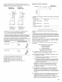
D_charge a D_charge
travers le toit travers le mur
A
A. Bouche de A. Bouche de
d_charge sur toit d_charge murale
B. Conduit rond B. Conduit rond
6" (15,2 cm)* 6" (15,2 cm)*
*La hotte de 48" (121,9 cm) utilise deux conduits ronds de
6" (15,2 cm) ou des raccords de transition ronds de
10" (25,4 cm); utiliser la piece numero 4396915.
Calcul de la Iongueur effective du circuit d'_vacuation
Pour calculer la Iongueur effective du circuit d'evacuation
necessaire, additionner les Iongueurs equivalentes (pieds/metres)
de tous les composants utilises dans le systeme.
Composant Longueur _quivalente
Coude & 45 ° 2,5 pi
(0,8 m)
Coude & 90 ° 5 pi
(1,5 m)
Les Iongueurs equivalentes maximales sont :
Conduit rond de 6" (15,2 cm) - 35 pi (10,7 m)
Conduit rond de 7" (17,8 cm) - 40 pi (12,2 m)
Conduit rond de 8" (20,3 cm) - 50 pi (15,2 m)
Conduits ronds de 9" (22,9 cm) et de 10" (25,4 cm) -
60 pi (18,3 m)
Exemple de syst_me de d_charge
Bouche de
Co.de0oo 0 I
L'exemple suivant indique la Iongueur de conduit recommandee
maximum.
1 coude it 90 ° = 5 pi (1,5 m)
1 bouche de decharge = 0 pi (0 m)
murale
Section droite de 8 pi = 8 pi (2,4 m)
(2,4 m)
Longueur du systeme = 13 pi (3,9 m)
Observer les dispositions de tous les codes et reglements en
vigueur.
L'installation electrique doit satisfaire les exigences de la plus
recente edition de lanorme National Electrical Code, ANSl/NFPA
70, ou de la norme CSA C22.1-94, Code canadien de I'electricite,
partie 1 et C22.2 N° 0-M91 (derniere edition) et de tousles codes
et reglements en vigueur Iocaux.
Si les codes le permettent et si on utilise un conducteur distinct
de liaison a la terre, il est recommande qu'un electricien qualifie
verifie la qualite de la liaison & la terre.
Pour obtenir un exemplaire de la norme des codes ci-dessus,
contacter :
National Fire Protection Association
One Batterymarch Park
Quincy, MA 02269
CSA International
8501 East Pleasant Valley Road
Cleveland, OH 44131-5575
• L'appareil doit _tre alimente par un circuit de 120 V, CA
seulement, 60 Hz, 15 A, proteg6 par fusible.
• Si le domicile est equip6 d'un c&blage en aluminium, suivre
les instructions suivantes :
1. Connecter une section de c&ble en cuivre massif aux
conducteurs en queue de cochon.
2. Connecter le c&blage en aluminium a la section ajoutee
de c&blage en cuivre en utilisant des connecteurs et/ou
des outils specialement con(_us et homologu6s UL pour
fixer le cuivre a I'aluminium.
Appliquer la procedure recommandee par le fabricant des
connecteurs. La connexion aluminium/cuivre doit _tre
conforme aux codes Iocaux et aux pratiques de c&blage
acceptees par I'industrie.
Le calibre des conducteurs et les connexions doivent _tre
compatibles avec la demande de courant de I'appareil
specifi6e sur la plaque signaletique. La plaque signaletique
de I'appareil est situ6e derriere le filtre, sur la paroi arriere de
la hotte.
Le calibre des conducteurs doit satisfaire les exigences de la
plus recente edition de la norme National Electrical Code,
ANSl/NFPA 70, ou de la norme CSA C22.1-94, Code
canadien de I'electricit6, partie 1 et C22.2 n° 0-M91 (derniere
edition) et de tousles codes et reglements en vigueur.
19

INSTRUCTIONS D'INSTALLATION
• II est recommande d'installer le systeme d'evacuation avant
de proceder a I'installation de la hotte.
• Avant d'executer les decoupages, verifier la disponibilite d'un
degagement suffisant dans le plafond ou lemur pour le
conduit d'evacuation.
Avant de selectionner la hotte & installer, mesurer la hauteur
libre sous plafond et la hauteur maximum disponible sous la
hotte.
1. Deconnecter la source de courant electrique.
2. Determiner la methode d'extraction & utiliser : decharge
travers le mur ou le toit.
3. Selectionner une surface plane pour I'assemblage de la
hotte. Placer le materiau de protection sur cette surface.
Risque du poids excessif
Utiiiser deux ou plus de personnes pour d_placer et
installer la hotte de la cuisini_re.
Le non=respect de cette instruction peut causer
une blessure au dos ou d'autre blessure.
4. A I'aide de deux personnes ou plus, soulever la hotte et la
poser sur la surface couverte.
Installation avec dosseret facultative
REMARQUE : Les instructions suivantes correspondent & un
dosseret sans tablette. Si I'on installe un dosseret avec des
tablettes pour les lampes chauffantes, suivre les instructions
fournies avec ce produit-I&. (Voir "Accessoires" & la section
"Assistance ou Service" pour passer une commande.)
Le materiel de montage fourni avec I'ensemble comprend
4 chevilles d'ancrage mural en plastique et 4 vis de montage.
• La hauteur de la hotte est en fonction de la hauteur du
dosseret.
REMARQUE : La hauteur minimale de la hotte au-dessus de
la table de cuisson est de 30" (76,2 cm). Le dosseret peut
_tre rallonge de 1923/32"(50,1 cm) & 39" (99,1 cm). Au fur et &
mesure que la hauteur de I'installation de 30" (76,2 cm)
augmente, la zone de fixation de lahotte diminue.
Determiner la hauteur de la hotte.
A I'aide d'au moins 2 personnes, placer le dosseret sur lemur
de fagon &ce que le sommet du dosseret se trouve &hauteur
de la rive inferieure de la hotte. Marquer I'emplacement des
4 trous d'angle. II est recommande que le dosseret soit fixe
au mur au niveau des 4 angles. Cependant, le rebord inferieur
peut _tre fixe entre lemur et le dosseret, le plan de travail ou
la base du placard sans avoir & utiliser les vis de coin
inferieur.
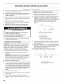
Installation des vis de montage de la hotte
1.
2.
Determiner I'emplacement de I'axe central oQ la hotte sera
installee et tracer une ligne & cet endroit sur le mur.
En fonction de la hauteur sous plafond ou soffite, determiner
la distance "X" (30" [76,2 cm] min et 36" [91,4 cm] max.
sugger6e) necessaire entre la surface de cuisson et le bas de
la hotte. A cette distance, ajouter 19" (48,3 cm) et tracer une
ligne horizontale (A) d'environ 24" (61 cm) de Iongueur
centree par rapport & I'axe central vertical (B) a cette
distance.
f
c\
\
B\ x + 19"(48,"_3ore)
1
1
I
A. Ligne horizontale
B. Axe central vertical
C. Surface de cuisson
D. Distance "X" (30" [76,2 cm] min.,
36" [91,4 cm] max. sugg_r_e)
3. En suivant les illustrations de I'etape 4, marquer un point de
chaque c6te de la ligne horizontale en mesurant & partir de
I'axe central vertical.
4. Percer des avant-trous de 3/32"(2,4 mm) pour une installation
dans du bois. Les vis fournies pour le montage de cette hotte
doivent _tre fixees dans du bois massif. Ne pas fixer
uniquement dans du placo-pl&tre.
Pour modules de 36" (91,4 cm) - 2 trous de montage
A
%%
I I
; .........iT
.............................///
C
A. Ligne horizontale
B.Axe central vertical de la hotte
C. 49/ld' (11,6 cm)
• Percer des trous de s/le"(8 mm).
• Enfoncer completement les chevilles d'ancrage en plastique
dans les trous.
• Positionner les trous dans le dosseret par-dessus les
chevilles d'ancrage mural et fixer le dosseret & I'aide des vis
fournies.
20
La page est en cours de chargement...
La page est en cours de chargement...
La page est en cours de chargement...
La page est en cours de chargement...
La page est en cours de chargement...
La page est en cours de chargement...
La page est en cours de chargement...
La page est en cours de chargement...
-
 1
1
-
 2
2
-
 3
3
-
 4
4
-
 5
5
-
 6
6
-
 7
7
-
 8
8
-
 9
9
-
 10
10
-
 11
11
-
 12
12
-
 13
13
-
 14
14
-
 15
15
-
 16
16
-
 17
17
-
 18
18
-
 19
19
-
 20
20
-
 21
21
-
 22
22
-
 23
23
-
 24
24
-
 25
25
-
 26
26
-
 27
27
-
 28
28


KitchenAid KWCU460WS00 Guide d'installation
- Catégorie
- Hottes
- Taper
- Guide d'installation
- Ce manuel convient également à
dans d''autres langues
Documents connexes
-
KitchenAid KWCU320WSS0 Le manuel du propriétaire
-
-
KitchenAid KWCU360JSS1 Le manuel du propriétaire
-
-
-
-
-
-
KitchenAid 48" Le manuel du propriétaire
-