SportsArt TR9800 Le manuel du propriétaire
- Catégorie
- Tapis de course
- Taper
- Le manuel du propriétaire

TABLE OF CONTENTS
CHAPTER 1: SAFETY INSTRUCTIONS
CHAPTER 2: UNPACKING THE TREADMILL
CHAPTER 3: PRODUCT ASSEMBLY
CHAPTER 4:
CHAPTER 5:
CHAPTER 6:
1.1 SAFETY PRECAUTIONS....................................................................................
1.2 ABOUT THIS MANUAL.......................................................................................
2.1 INTRODUCTION.................................................................................................
2.2 SPECIFICATIONS...............................................................................................
2.3 COMPONENTS IN THE CARTON......................................................................
2.4 COMPONENTS IN THE HARDWARE KIT..........................................................
2.5 COMPONENTS ON THE PRODUCT..................................................................
3.1 INSTALLATION REQUIREMENTS....................................................................
3.2 ASSEMBLY INSTRUCTIONS.............................................................................
3.3
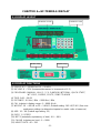
4.1 DISPLAY LAYOUT...............................................................................................
4.2
4.3
4.4
DISPLAY
STEP 1 Assemble the Left and Right Pedestals and Handlebars.....................
STEP 2 Install the Display.................................................................................
STEP 3 How to Move the Treadmill...................................................................
STEP 4 Leveling the Unit...................................................................................
STEP 5 Align the Walk Belt................................................................................
STEP 6 Adjust Walk Belt Tightness...................................................................
STEP 7 Install the Power Cord..........................................................................
Replacing the Fuse
SAFETY KEY USAGE........................................................................................
DISPLAY FUNCTIONS........................................................................................
DISPLAY KEYS...................................................................................................
SAFETY FEATURES...........................................................................................
5.1 STARTING YOUR TREADMILL...........................................................................
5.2 QUICK START......................................................................................................
5.3 WORKOUT SETUP..............................................................................................
5.4 WORKOUT PROGRAMS.....................................................................................
5.5 USER PARAMETER SETTINGS.........................................................................
HOW TO USE YOUR TREADMILL
STEP 8 ...............................................................................
6.1 HEART RATE TELEMETRY................................................................................
6.2 CONTACT HEART RATE....................................................................................
HF-TR9800-G
HF-TR9800-G
1
5
6
7
8
9
9
10
10
13
20
23
24
25
26
27
28
29
31
31
32
34
35
35
35
36
37
38
38
ABOUT HEART RATE DETECTION AND PRESENTATION

CHAPTER 7: GUIDELINES FOR EXERCISE
CHAPTER 8: MAINTENANCE
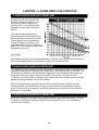
7.1 HOW HARD SHOULD I EXERCISE?.................................................................
7.2 HOW LONG SHOULD I EXERCISE?..................................................................
7.3 HOW OFTEN SHOULD I EXERCISE?................................................................
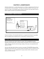
8.1 TREADMILL LUBRICATION KIT.........................................................................
8.2 THE LUBRICATION PROMPT............................................................................
8.3 CLEARING THE SERVICE NEEDED MESSAGE..............................................
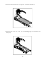
8.4 MANUAL LUBRICATION PROCEDURE............................................................
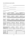
8.5 MAINTENANCE CHECKLIST............................................................................
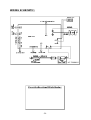
WIRING SCHEMATIC.................................................................................................
40
40
40
41
41
46
46
46
50

CHAPTER 1 SAFETY PRECAUTIONS-
1.1 SAFETY PRECAUTIONS
-1-

-2-
.
DO NOT use accessories that are not specifically recommended by the manufacturer.
Such parts might cause injuries or cause the unit to fail.

180 (400 ).
kg
-3-
any
20
180 KGS (400 LBS).
Note that the 12 mph (20 kph) rating good up to 125 kgs (275 lbs).Note that the rating is good for users up to 150 (330 ).KGS
LBS
KGS
LBS
150
(330 ).
LBS
12
20
MPH
KPH
12
20
MPH
KPH
20 Amp
10 Amp

Improper connection of the equipment-grounding connector can result in a risk of electric
shock. Check with a qualified electrical or service person if you are in doubt as to whether
the treadmill is properly grounded. DO NOT modify the plug provided with the product;
if it doesn't fit the outlet, have the proper outlet installed by a qualified technician.
-4-
Note: This equipment has been tested and found to comply with the limits for a Class B
digital device, pursuant to part 15 of the FCC Rules. These limits are designed to
provide reasonable protection against harmful interference in a residential
installation. This equipment generates, uses and can radiate radio frequency
energy and, if not installed and used in accordance with the instructions, may
cause harmful interference to radio communications. However, there is no
guarantee that interference will not occur in a particular installation.
If the user desires to correct the interference, it is at the user's own expense.
Remarque: Ce matériel a été testé et déclaré conforme aux normes des appareils
digitaux de Classe B, conformément à la partie 15 du Règlement de la
FCC. Ces limites sont conçues pour offrir une protection raisonnable
contre les interférences nuisibles dans une installation résidentielle.

1.2 ABOUT THIS MANUAL
This manual provides instructions for the assembly, installation, and operation of the
Treadmill. Please study this manual thoroughly to prevent injury to
exercisers and damage to the product. Please save these instructions for future
reference. Make sure that product users abide by instructions in this manual.
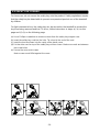
This manual uses the following conventions for identifying special information:
Indicates additional information.
Indicates information to which you should pay special attention.
Indicates information to prevent harming the user or damaging the
product.
Note:
Important:
CAUTION:
HF-TR9800-G
-5-
Cet appareil génère, utilise, et peut diffuser des signaux radioélectriques,
et, s'il n'est pas installé et utilisé conformément aux instructions, peut
provoquer des interférences nuisibles aux communications radio.
Cependant, il n'y a aucune garantie que des interférences ne se produiront
pas dans une installation particulière.)
Si l'utilisateur désire corriger les interférences, ces corrections seront à la
charge de l'utilisateur.
In this manual, the words “left” and “right” are used in reference to parts and the
product. As such, the words “left” and “right” equate to the excerciser's left and right
sides respectively. Also, for brevity, the word “screws” is used in some cases where
washers, screws, and other hardware are involved.
Dans ce manuel, les mots “gauche” et “droit” sont utilisés en référence aux pièces et
au produit. Comme tels, les mots “gauche” et “droit” font respectivement référence aux
côtés gauche et droit de l'exerciseur. De même pour plus de concision, le mot "vis" est
utilisé dans certains cas où des rondelles, des vis et autres matériels sont associés.

-6-
Thank you for purchasing a high quality product from Fitness. Constructed of robust
materials and built for years of trouble-free usage, the Treadmill
was designed and manufactured to become an integral part of your fitness regimen.
This product is a unique tool made to help you obtain your fitness goals. But like every
tool, it must be used properly. Please read and abide by instructions in this manual.
Understanding the correct use of this equipment will help you achieve your exercise
goals safely and effectively.
HF-TR9800-G
CHAPTER 2UNPACKING THE TREADMILL-
2.1 INTRODUCTION

Specifications
Running surface: 22" x 61" inches
Speed Range: 0.1- 12 mph; 0.2- 20 kph; Motor: 3.2 HP
Incline Range: 0-15%
Programs:
Feedback:
Display Type: LED
Heart Rate Control: Yes
Maximum User Weight: 400 lbs; 180 kgs
Dimensions : 2120mm x 980mmx 1430mm83.5" X 38.6" X 56.3")(
HF-TR9800-G
MANUAL, HILL, RANDOM, INTERVAL, QUICK START, WT LOSS, CARDIO,
GLUTE, ZONE TRAINER
CALORIES, SPEED, TIME, DISTANCE, CAL/HR, METS, PACE, INCLINE,
HEART RATE, WT LOSS 65%, CARDIO 80%.
-7-
2.2 SPECIFICATIONS

No. Name Qty
No.
QtyDescription
A1
A2
A3
A4
A5
A6
A6a
A6b
1
1
1
1
2
1
1
1
1
1
1
1
1
4
Assembly Parts
A7
A8
A9
A10
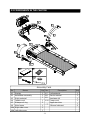
2.3 COMPONENTS IN THE CARTON
-8-
Display
Handlebar assembly
Right pedestal
Feeder cord
Waterproof ring
Main frame
Right side cover
Left side cover
A11
Left pedestal
Owner manual
Hardware kit
Power cord
Applicator tube
Silicone lubricant

-9-
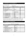
A hardware kit is provided in the packaging of this product. Please inspect the hardware
kit for the following items.
2.4 COMPONENTS IN THE HARDWARE KIT
If you discover items missing or damaged in shipping, please contact the Service
Department. Keep the hardware kit in a secure place for future use. Tools may be
needed to disassemble the product in preparation for moving or other activities.
2.5 COMPONENTS ON THE PRODUCT
Some components are installed on the product. These items will be needed for product
assembly.
No. Name Qty NotesSpecification
31
32
33
2
2
6
4
4
1
1
1
1
1
1
1
1
1
15A-100V~110V
10A-200V~220V
(M4)
(M5)
(M6)
(M6)
(22)
green
M4*L16
*24
No. Name
Qty
NotesSpecification
Screw cover
Screw
MushroomtopPhillipsscrew
Screwsocket
Screw clip
L-shaped Allen wrench
L-shaped Allen wrench
L-shaped Allen wrench
T-shaped Allen wrench
Double open-end wrench
Screwdriver handle
(rounded)
cover(flat)
Screwdriver bit
Hardware Kit
No.
Name
41
Components on the Product
43
44
42
45
Specification
M8*L20
M8
18* 8.5*t2
M8*L20
18* 8.5*t2
M8*L20
18* 8.5*t2
M5*L12
M4*L8
Fuse
Inner hex screw
Spring washer
Star washer
Mushroom top inner hex screw
Serratedwashercurved
Mushroom top inner hex screw
Serratedwasher
Mushroom top inner hex screw
Phillips head screw
()
ψψ
ψψ
ψψ
Phillips and flat

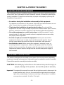
The challenge of product installation depends highly on the area in which the product
will be used. Stairs, doorways and other obstacles must be considered in planning for
product installation. Please ensure the safety of people and property in planning the
installation of any product.
Pay attention to instructions in this manual. Get help if you feel instructions are not
clear. Prevent injury to people and damage to the product.
Do not install this
equipment in an area of high humidity. Exposure to extensive water vapor, chlorine,
bromine, ammonia, and other chemicals could adversely affect this equipment.
Install this product in a safe,
secure location. A solid, level, smooth surface is required to ensure user safety
and proper product operation.
Leave space around the
equipment to allow users to safely mount and dismount the product. Ensure
enough space above the product to allow for comfortable, safe operation.
Before moving this equipment, removing covers, or
accessing electronic components, make sure the power switch is off and the
product is disconnected from the power outlet. Be aware that some electronic
components retain an electric charge for a few seconds after power supply is
disconnected.
˙
˙
˙
˙
˙
Be cautious during the installation and assembly of this equipment.
Think about the installation site and product location.
Set up the equipment on a solid, level surface.
Provide enough space around the equipment.
Avoid electric shock.
CHAPTER 3PRODUCT ASSEMBLY-
3.1 INSTALLATION REQUIREMENTS
3.2 ASSEMBLY INSTRUCTIONS
This product is designed for assembly by one person. But in some cases, depending
on personal strength and experience, two people may be needed for product assembly.
Please follow product assembly instructions carefully.
Throughout this manual, the words left and right are used in reference to the
product and its parts. As such, the words left and right refer to the left and
right sides, respectively, of someone exercising on the product. In addition,
some parts are marked for left or for right.
CAUTION: Not abiding by instructions in this manual may result in injury to
people, damage to the product, and void the product warranty.
Important:
LR
-10-

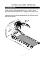
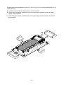
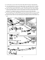
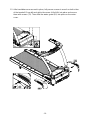
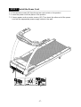
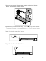
RemovepackagingmaterialinorderABandCasshowntosetthetreadmillflatonits
cardboardbox
ACutthecornersofthecardboardboxtolaytheboxflat
BLiftthebackendofthetreadmillandremovepackagingmaterialinthebackand
centerofthetreadmill
CLiftthefrontendofthetreadmillandremovepackagingmaterialatthefrontendof
thetreadmill
, ,
.
. .
.
.
.
.
-11-

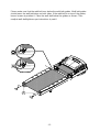
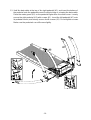
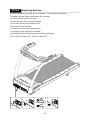
Please make sure that the walk belt runs below the walk belt guides. Walk belt guides
should press the walk belt down on both sides. If the walk belt is on top of the guides,
loosen screws at position A. Place the walk belt below the guides as shown. Then
readjust walk belt tightness per instructions in part 6.
-12-
A

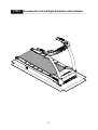
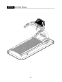
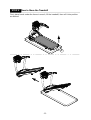
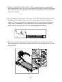
STEP 1 Assemble the Left and Right Pedestals and Handlebars
-13-

-14-
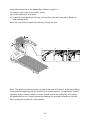
1-1. Remove screws (41) from the pedestal mount area. Inspect whether the screw
sockets in areas A and B are in place on the product. If not, remove them from the
hardware kit and insert them into place on the product.
B
A

-15-
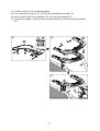
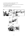
12.Followstepsad)inordertothreadthedatacablethroughtherightpedestal
aIntherightpedestalmountareathedatacableissecuredwithaziptieCarefully
cuttheziptietofreethedatacablePullthedatacablethroughtheovalopening
bPlacetherightpedestal A3flatonthefloorwiththebottomareaofthepedestal
nearesttothedatacableDisconnectthefeedercord A4fromthebottomofthe
pedestalThenattachthefeedercord A4)tothetoppartofthedatacable
Fromthetoppartoftherightpedestal A3disconnectthefeedercord A4)Pullthe
toppartofthefeedercord A4)tothreadthedatacablethroughthepedestalA3
dOncethedatacablehasbeenfedthroughthepedestaldisconnectthefeedercord
A4).
- ~ .
, .
. .
,
.
. .
.
.
,
(
()
() ()
()
(
(c) ()(
(()
()
(
(b)
(a)
(c)
(d)

-16-
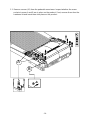
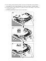
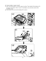
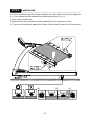
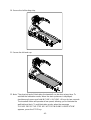
1-3. Hold the data cable at the top of the right pedestal (A3), and insert the bottom of
the pedestal onto the pedestal mount. Avoid pinching or crimping the data cable.
Place the water guard (A5) on the pedestal higher than the motor cover. Loosely
secure the right pedestal (A3) with screws (41). Insert the left pedestal (A7) onto
its pedestal mount, and loosely secure it with screws (41). Do not tighten screws.
Make sure the pedestals can still move slightly.

-17-
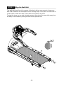
1-4. Follow steps (a~e) to install handlebars.
First, remove the screws (42, 43) from the handlebar assembly (A2).
Insert the left side of the handlebar (A2) into the left pedestal (A7).
Connect the cables in area A from the right pedestal (A3) and from the handlebar
(A2).
(a)
(b)
(c)
(b)
(a)
(c)
A

-18-
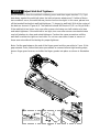
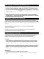
(d) Tuck cables into the pedestal safely. Then insert the right side of the handlebar
assembly (A2) into the right pedestal (A3), without pinching or crimping cables.
(e) Thread screws in place by hand. First, secure screws (42) in area B. Then secure
screws (43) in area C.
( ) Insert the screw cap (31)(32) onto the screw head.
(d)
(e)
(f)
C
B
B
f
La page est en cours de chargement...
La page est en cours de chargement...
La page est en cours de chargement...
La page est en cours de chargement...
La page est en cours de chargement...
La page est en cours de chargement...
La page est en cours de chargement...
La page est en cours de chargement...
La page est en cours de chargement...
La page est en cours de chargement...
La page est en cours de chargement...
La page est en cours de chargement...
La page est en cours de chargement...
La page est en cours de chargement...
La page est en cours de chargement...
La page est en cours de chargement...
La page est en cours de chargement...
La page est en cours de chargement...
La page est en cours de chargement...
La page est en cours de chargement...
La page est en cours de chargement...
La page est en cours de chargement...
La page est en cours de chargement...
La page est en cours de chargement...
La page est en cours de chargement...
La page est en cours de chargement...
La page est en cours de chargement...
La page est en cours de chargement...
La page est en cours de chargement...
La page est en cours de chargement...
La page est en cours de chargement...
La page est en cours de chargement...
-
 1
1
-
 2
2
-
 3
3
-
 4
4
-
 5
5
-
 6
6
-
 7
7
-
 8
8
-
 9
9
-
 10
10
-
 11
11
-
 12
12
-
 13
13
-
 14
14
-
 15
15
-
 16
16
-
 17
17
-
 18
18
-
 19
19
-
 20
20
-
 21
21
-
 22
22
-
 23
23
-
 24
24
-
 25
25
-
 26
26
-
 27
27
-
 28
28
-
 29
29
-
 30
30
-
 31
31
-
 32
32
-
 33
33
-
 34
34
-
 35
35
-
 36
36
-
 37
37
-
 38
38
-
 39
39
-
 40
40
-
 41
41
-
 42
42
-
 43
43
-
 44
44
-
 45
45
-
 46
46
-
 47
47
-
 48
48
-
 49
49
-
 50
50
-
 51
51
-
 52
52


SportsArt TR9800 Le manuel du propriétaire
- Catégorie
- Tapis de course
- Taper
- Le manuel du propriétaire
dans d''autres langues
- English: SportsArt TR9800 Owner's manual
Documents connexes
-
SportsArt TR9750 Le manuel du propriétaire
-
-
-
-
-
-
-
-
-