
Directional Power Sensors
Operation Manual
Model 5009, 5010B, and 5014
©Copyright 2017
by Bird Technologies Inc.
Instruction Book Part Number 920-5010S Rev. E

BirdDirectionalPowerSensors
i
Safety Precautions
Thefollowingaregeneralsafetyprecautionsthatarenotnecessarilyrelatedto
anyspecificpartorprocedure,anddonotnecessarilyappearelsewhereinthis
publication.Theseprecautionsmustbethoroughlyunderstoodandapplytoall
phasesofoperationandmaintenance.
WARNING
KeepAwayFromLiveCircuits
OperatingPersonnelmustatalltimesobservegeneralsafetyprecautions.Do
notreplacecomponentsormakeadjustmentstotheinsideofthetest
equipmentwiththehighvoltagesupplyturnedon.Toavoidcasualties,alwa ys
removepower.
WARNING
ShockHazard
DonotattempttoremovetheRF
transmissionlinewhileRFpowerispresent.
WARNING
DoNotServiceOrAdjustAlone
Undernocircumstancesshouldanypersonreachintoanenclosureforthe
purposeofserviceoradjustmentofequipmentexceptinthepresenceof
someonewhoiscapableofrenderingaid.
WARNING
SafetyEarthGround
Anuninterruptibleearthsafetyground
mustbesuppliedfromthemain
powersourcetotestinstruments.Groundingoneconductorofatwo
conductorpowercableisnotsufficientprotection.Seriousinjuryordeathcan
occurifthisgroundingisnotproperlysupplied.
WARNING
Resuscitation
Personnelworkingwithornearhighvoltagesshouldbefamiliarwithmodern
methods
ofresuscitation.
WARNING
RemovePower
Observegeneralsafetyprecautions.Donotopentheinstrumentwiththe
poweron.

SafetyPrecautions
ii
Safety Symbols
Note: Callsattentiontosupplementalinformation.
Warning Statements
Thefollowingsafetywarningsappearinthetextwherethereisdangerto
operatingandmaintenancepersonnel,andarerepeatedhereforemphasis.
Onpage2.
Onpage5.
Onpage5.
WARNING
Warningnotescallattentiontoaprocedure,whichifnotcorrectlyperformed,
couldresultinpersonalinjury.
CAUTION
Cautionnotescallattentiontoaprocedure,whichifnotcorrectlyperformed,
couldresultindamagetotheinstrument.
WARNING
LeakingRFenergyisapotentialhealthhazard.DONOTconnectordisconnect
equipment
fromthetransmissionlinewhileRFpowerisbeingapplied.Severe
burns,electricalshock,ordeathcanoccur.
WARNING
NeverattempttoconnectordisconnectRFequipmentfromthetransmission
linewhileRFpowerisbeingapplied.
LeakingRFenergyisapotentialhealthhazard.
WARNING
RFvoltagemaybepresentinRF
elementsocket.Keepelementinsocket
duringoperation.

BirdDirectionalPowerSensors
iii
Caution Statements
Thefollowingequipmentcautionsappearinthetextandarerepeatedherefor
emphasis.
Onpage2.
Safety Statements
USAGE
ANY USE OF THIS INSTRUMENT IN A MANNER NOT SPECIFIED BY
THE MANUFACTURER MAY IMPAIR THE INSTRUMENT’S SAFETY
PROTECTION.
USO
EL USO DE ESTE INSTRUMENTO DE MANERA NO ESPECIFICADA
POR EL FABRICANTE, PUEDE ANULAR LA PROTECCIÓN DE
SEGURIDAD DEL INSTRUMENTO.
BENUTZUNG
WIRD DAS GERÄT AUF ANDERE WEISE VERWENDET ALS VOM
HERSTELLER BESCHRIEBEN, KANN DIE GERÄTESICHERHEIT
BEEINTRÄCHTIGT WERDEN.
UTILISATION
TOUTE UTILISATION DE CET INSTRUMENT QUI N’EST PAS
EXPLICITEMENT PRÉVUE PAR LE FABRICANT PEUT
ENDOMMAGER LE DISPOSITIF DE PROTECTION DE
L’INSTRUMENT.
IMPIEGO
QUALORA QUESTO STRUMENTO VENISSE UTILIZZATO IN MODO
DIVERSO DA COME SPECIFICATO DAL PRODUTTORE LA
PROZIONE DI SICUREZZA POTREBBE VENIRNE COMPROMESSA.
CAUTION
Iftheelementcannotbefullyinsertedintothesocket,donotforceit.This
maydamagetheelement.

SafetyPrecautions
iv
SERVICE
SERVICING INSTRUCTIONS ARE FOR USE BY SERVICE - TRAINED
PERSONNEL ONLY. TO AVOID DANGEROUS ELECTRIC SHOCK, DO
NOT PERFORM ANY SERVICING UNLESS QUALIFIED TO DO SO.
SERVICIO
LAS INSTRUCCIONES DE SERVICIO SON PARA USO EXCLUSIVO
DEL PERSONAL DE SERVICIO CAPACITADO. PARA EVITAR EL
PELIGRO DE DESCARGAS ELÉCTRICAS, NO REALICE NINGÚN
SERVICIO A MENOS QUE ESTÉ CAPACITADO PARA HACERIO.
WARTUNG
ANWEISUNGEN FÜR DIE WARTUNG DES GERÄTES GELTEN NUR
FÜR GESCHULTES FACHPERSONAL.
ZUR VERMEIDUNG GEFÄHRLICHE, ELEKTRISCHE SCHOCKS, SIND
WARTUNGSARBEITEN AUSSCHLIEßLICH VON QUALIFIZIERTEM
SERVICEPERSONAL DURCHZUFÜHREN.
ENTRENTIEN
L’EMPLOI DES INSTRUCTIONS D’ENTRETIEN DOIT ÊTRE RÉSERVÉ
AU PERSONNEL FORMÉ AUX OPÉRATIONS D’ENTRETIEN. POUR
PRÉVENIR UN CHOC ÉLECTRIQUE DANGEREUX, NE PAS
EFFECTUER D’ENTRETIEN SI L’ON N’A PAS ÉTÉ QUALIFIÉ POUR CE
FAIRE.
ASSISTENZA TECNICA
LE ISTRUZIONI RELATIVE ALL’ASSISTENZA SONO PREVISTE
ESCLUSIVAMENTE PER IL PERSONALE OPPORTUNAMENTE
ADDESTRATO. PER EVITARE PERICOLOSE SCOSSE ELETTRICHE
NON EFFETTUARRE ALCUNA RIPARAZIONE A MENO CHE
QUALIFICATI A FARLA.

BirdDirectionalPowerSensors
v
RF VOLTAGE MAY BE PRESENT IN RF ELEMENT SOCKET - KEEP
ELEMENT IN SOCKET DURING OPERATION.
DE LA TENSION H.F. PEAT ÊTRE PRÉSENTE DANS LA PRISE DE
L'ÉLÉMENT H.F. - CONSERVER L'ÉLÉMENT DANS LA PRISE LORS
DE L'EMPLOI.
HF-SPANNUNG KANN IN DER HF-ELEMENT-BUCHSE ANSTEHEN -
ELEMENT WÄHREND DES BETRIEBS EINGESTÖPSELT LASSEN.
PUEDE HABER VOLTAJE RF EN EL ENCHUFE DEL ELEMENTO RF -
MANTENGA EL ELEMENTO EN EL ENCHUFE DURANTE LA
OPERACION.
IL PORTAELEMENTO RF PUÒ PRESENTARE VOLTAGGIO RF -
TENERE L'ELEMENTO NELLA PRESA DURANTE IL
FUNZIONAMENTO.

AboutThisManual
vi
About This Manual
Thismanualcoverstheoperatingandmaintenanceinstructionsforthe
followingmodels:
Changes to this Manual
Wehavemadeeveryefforttoensurethismanualisaccurate.Ifyoudiscoverany
errors,orifyouhavesuggestionsforimprovingthismanual,pleasesendyour
commentstoourSol on,Ohiofactory .Thismanualmaybeperiodicallyupdated.
Wheninquiringaboutupdatestothismanualrefertothepart
numberand
revisiononthetitlepage.
Chapter Layout
Introduction — DescribesthefeaturesoftheDirectionalPowerSensorand
ElementTypes.
Installation — DescribeshowtoconnectionandinstalltheDirectionalPower
Sensorintothesystemthatisbeingmonitored.
Specifications — Describesthebasicinformation,settings,andrangesofthe
DigitalPowerSensor.
5009 5010B 5014
5010T

vii
Table of Contents
Safety Precautions . . . . . . . . . . . . . . . . . . . . . . . . . . . . . . . . . . . . . . . . . i
SafetySymbols................................................
.. ii
WarningStatements............................ ................. ii
Caution
Statements....................... .......................iii
SafetyStatements..
.............................................iii
About This Manual . . . . . . . . . . . . . . . . . . . . . . . . . . . . . . . . . . . . . . . . vi
ChangestothisManual.
............... ..................... ......vi
ChapterLayout.......
............... ..................... ......vi
Chapter 1 Introduction . . . . . . . . . . . . . . . . . . . . . . . . . . . . . . . . . . . . . 1
Description ........
............................................. 1
ElementTypes...
................................... ............ 1
43TypeElements
........................... ................. 1
APM/DPMElements....
................................... ... 1
ElementOrientation..........
................................... 2
ElementContactAlignment............
........................ 2
Chapter 2 Installation . . . . . . . . . . . . . . . . . . . . . . . . . . . . . . . . . . . . . . 4
UnpackingandInspection......................
............... .... 4
ConnectingtheDirectionalPowerSensor(DPS)... .................... 5
Chapter 3 Specifications. . . . . . . . . . . . . . . . . . . . . . . . . . . . . . . . . . . . 8
5009Specifications
.............................................. 8
5010B,5010TSpecifications .
................................... .. 10
5014Specifications..... .. ....
.................................. 12
CustomerService..............
................................. 14
Limited Warranty . . . . . . . . . . . . . . . . . . . . . . . . . . . . . . . . . . . . . . . . . 15

1
Chapter 1 Introduction
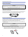
Description
TheDPSPowerSensorsareintendedforuseincoaxialtransmissionlinesof50
ohmnominalimpedance.Thesensorsutilizeelementsinordertomakepower
measurements.Eachelementhasanarrowonitthatrepresentsthedirectionin
whichitmeasurespower.Theelementsignorepowerintheoppositedirection
withadirectivityofatleast25dB.TheDPSseriescanmakepower
measurementsusingeither43typeorAPM/DPMelements,andthereadings
availablevary,basedonwhichelementsarebeingused.
SincetheDPSusestwoelements,itcanmeasurethequalityofthesystemby
comparingtheforwardandthereflectedpower.Thisisusuallypresentedinthe
formofVSWR(voltagestandingwaveratio)orReturnLoss.
Element Types
43 Type Elements
The43typeelementsarenormallyusedtomeasurepeakpower.These
elementscanmeasurethepeakpowerofasystemwithanaccuracyof+/‐8%of
fullscaleaslongasthesignalmeetsthefollowingrequirements:
Atleast15pulsespersecond(PPS
Minimumpulsewidthof15µs(800nsiffrequencyisgreaterthan100
MHz)
MinimumDutyCycleof0.01%
Inaddition,43typeelementscanbeusedtomeasureaveragepowerinsignals
withapeak‐to‐averageratiocloseto1,likeaCWorFMsignals.Inthesecases,
theaveragepowerismeasuredwithanaccuracyof+/‐5%offullscale.
APM/DPM Elements
TheAPM/DPMelementsareusedtomeasuretrueaveragepower.Trueaverage
powermeansthesensorprovidesequivalentheatingpowerofthesignal,
regardlessofmodulationornumberofcarriers.Theseelementscanmeasure
averagepowerwithanaccuracyof+/‐5%ofreadingfromfullscaledownto
2.5%of
fullscale.
Note: Theequivalentheatingpowerisdependentontheduty
cycleofasignal.Ifasystemputsout50wattswitha50%duty
cycle,theAPM/DPMelementswillmeasure25watts.

BirdDirectionalPowerSensors
2
Element Orientation
Theforwardelementandthereflectedelementmustbeofthesameseries
(APMor43).Thepowerratingoftheforwardelementmustbe10xthepower
ratingofthereverseelement.
Inserttheforwardelementintotheforwardsocketwithitsarrowpointinginthe
directionofforwardpower.Insertthereflectedelementintothereflected
socketwithitsarrowpointinginthedirectionofreversepower.
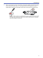
Element Contact Alignment
Continuousinsertionorrotationoftheelementmightcauseaslightchangein
thepositionofthecontactspringintheelementsocket.Ifthe contactspring
changesposition,erraticpowerreadingsmaybeexperienced.
Thepositionofthecontactspringmaybeadjustedwithasmallscrewdriverto
reestablishcontact.
Performthefollowingstepstoadjustthecontactspring:
1. Usingasmallflatheadscrewdriver,placetheflatsideofthescrewdriver
behindthecontactbarasindicatedandbendthecontactbarsothatthe
contactrestsinthecenteroftheslotadjacenttotheelementsocket.
WARNING
LeakingRFenergyis apotentialhealthhazard.DONOTconnectordisconnect
equipmentfromthetransmissionlinewhileRFpowerisbeingapplied.Severe
burns,electricalshock,ordeathcanoccur.
CAUTION
Iftheelementcannotbefullyinsertedintothesocket,donotforceit.This
maydamagethe
element.
O
u
t
p
u
t
R
e
f
l
e
c
t
e
d
F
o
r
w
a
r
d
I
n
p
u
t
O
u
t
p
u
t

Introduction
3
2. Aftercenteringthecontact,bendthecontactbarslightlytowardthecenter
oftheelementsocketbore,sothattheprofileoftheelementcontactis
visiblewhenviewingtheelementsocketfromthetopofthesocketbore.
Note: Ifthecontactisaccidentallymovedtoofar,theelementwill
notslideintothesocket.Movethecontactbackintotherecessed
areaandrepeattheprocess.

4
Chapter 2 Installation
Unpacking and Inspection
1. Carefullyinsp ectshippingcontainerforsignsofdamage.
Iftheshippingcontainerisdamaged,donotunpacktheuni t.
ImmediatelynotifytheshippingcarrierandBirdTechnologies.
Iftheshippingcontainerisnotdamaged,unpacktheunit.Save
shippingmaterialsforrepackaging.
2. Inspectunitforvisualsignsofdamage.
Note: Ifthereisdamage,immediatelynotifytheshippingcarrier
andBirdTechnologies.

Installation
5
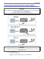
Connecting the Directional Power Sensor (DPS).
1. Dooneofthefollowing:
a. Toconnecta5009DPS:
Note: OnlyuseDPMelementsinthe5009DPS.
WARNING
Neverat tempttoconnectordisconnectRFequipmentfromthetransmission
linewhileRFpowerisbeingapplied.
LeakingRFenergyisapotentialhealthhazard.
WARNING
RFvoltagemaybepresentinRFelementsocket.Keepelementinsocket
duringoperation.

BirdDirectionalPowerSensors
6
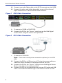
ConnectoneendofdatacabletotheRJ‐25connectoronthe5009.
Connecttheotherendofth
edatacabletooneofthechannel
inputconnectorsonaBirdChannelPowerMonitor.
Figure 1 5009 Cable Connection
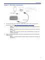
b. Toconnecta5010Bor5010TDPS:
ConnecttheDP
Stothe“Sensor”serialportontheBirdDigital
PowerMeterusingthesensorcableprovided.
Figure 2 5010 Cable Connection
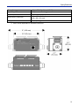
c. Toconnecta5014DPS:
Note: Therearecur
rentlythreeconnectionoptionsforthe5014
DPS.
ConnecttheDP
StoaUSBportonaPCusingthesensorcablepro‐
vided.UseVPM
3softwaretocommunicatewiththeDPS.
ConnecttheDP
Stothe“Sensor”USBportonaBirdDigitalPower
Meterusingthesensorcableprovided.
ConnecttheDPStoanAndr
oiddeviceusinganOTGcableandUSB
Cable.UsetheBirdRFMeterApptocommunicatewiththeDPS.

Installation
7
Figure 3 5014 Cable Connections
2. Connect theRFlinetotheDPSsothatthearrowonthesensorpoints
towardstheload,
see"ElementOri en tat io n" onpage 2
.
Note: Thear
rowontheforwardelementshouldpointtowards
theload.
Note: Thearrowonthereflectedelementshouldpointtowards
thesource.
Note: BothelementsmustbeeitherAPM/DPMor43types,do
notmixelements.
3. RefertoDPM
/VPM3/CPMmanualsforsetupparametersforthedesired
measurement.
Note: Us
etheforwardelement’spowerratingwhensettingup
thedevice.

8
Chapter 3 Specifications
5009 Specifications
SensorType Thrulinetwo‐elementlinesection
Elements
DPMelementsONLY
Selecttwoelementsfromthesameseries,withRFL
power1/10ofFWDpower.
FrequencyRange
1
2–1000MHz
1
Average Power Measurements
DPMElements,ForwardorReflectedDirection
PowerMeasurement
Range
0.1Wto1kW
PowerMeasurement
Accuracy
±5%offullscaleaveragepower(95%c.l.)
Match Measurement
MatchRange
ReturnLoss
Rho()
VSWR
0to20dB
0.1to1
1.22to99.99
Uncertainty
TwicetheAvgPowerUncertainty
(Calculatedfromforwardandreflecteduncertainty)
SettlingTime,Max 2.5seconds
Impedance,Nominal 50ohms
InsertionLoss,Max 0.05dBupto1GHz
InputVSWR,Max. 1.05:1upto1GHz
Directivity,Typical
1
30dB
RFConnectors QCType(N(F)normallysupplied)
InterfaceConnector RJ‐25
PowerSupply Fromhostinstrumentviainterfacecable
MechanicalShockand
Vibration
InaccordancewithMIL‐PRF‐28800FClass3
CE CEcompliant.RefertoDOCforspecificstandards.
RecommendedCalibration
Interval
1year
Temp,Operating –10to+50°C(+14to+122°F)

Specifications
9
Temp,Storage –40to+75°C(–40to+167°F)
Humidity,Max 95%(non‐condensing)
Altitude,Max 3,000m(10,000ft.)
Dimensions,Nominal
5.0”x2.4”x2.0”
(130x60x50mm)
Weight,Nominal 0.9lb.(0.4kg)
1Exactvaluedependsonelementselected

BirdDirectionalPowerSensors
10
5010B, 5010T Specifications
SensorType Thrulinetwo‐elementlinesection
Elements
5010B
5010T
Selecttwoelementsfromthesameseries,with
RFLpower1/10ofFWDpower.
APMor43serieselements
APMelementsonly
FrequencyRange
1
2–3600MHz
1
Average Power Measurement
APMElements,ForwardorReflectedDirection
PowerMeasurementRange
1
0.1Wto1kW
Accuracy
2
±5%ofreading(95%c.l.)
Peak/ AverageRatio,Max 10dB
DetectorResponse(5010Tonly) 230ms
43Elements,ForwardorReflectedDirection
PowerMeasurementRange 0.1Wto10kW
PowerMeasurementAccuracy ±5%offullscaleaveragepower(95%c.l.)
Peak Power Measurement
43Elementsonly,Forwarddirectiononly
PulseWidth,Min
2–25MHz
25–100MHz
>100MHz
15µs
1.5µs
800ns
Rep.Rate,Min 15PPS
DutyCycle,Min
1x10
–4
Accuracy
2
±8%offull‐scalepeakenvelopepower(95%c.l.)
Match Measurement
MatchRange
ReturnLoss
Rho(
)
VSWR
0to20dB
0.1to1
1.22to99.99
Uncertainty
TwicetheAvgPowerUncertainty
(Calculatedfromforwardandreflected
uncertainty)
SettlingTime,Max 2.5seconds
Impedance,Nominal 50ohms
InsertionLoss,Max 0.05dBupto1GHz

Specifications
11
InputVSWR,Max. 1.05:1upto1GHz
Directivity,Typical
1
30dB
RFConnectors QCType(N(F)normallysupplied)
InterfaceConnector DB‐9
PowerSupply Fromhostinstrumentviacable
MechanicalShockandVibration InaccordancewithMIL‐PRF‐28800FClass3
CE
CEcompliant.RefertoDOCforspecific
standards.
RecommendedCalibrationInterval 1year
Temp,Operating –10to+50°C(+14to+122°F)
Temp,Storage –40to+75°C
(–40to+167°F)
Humidity,Max 95%(non‐condensing)
Altitude,Max 3,000m(10,000ft.)
Dimensions,Nominal
5.0”x2.4”x2.0”
(130x60x50mm)
Weight,Nominal 0.9lb.(0.4kg)
1Exactvaluedependsonelementselected
2Above35°Corbelow15°Cadd2%

BirdDirectionalPowerSensors
12
5014 Specifications
SensorType Thrulinetwo‐elementlinesection
Elements
APMor43serieselements.Selecttwo
elementsfromthesameseries,withRFLpower
1/10ofFWDpower.
FrequencyRange
1
2–3600MHz
Average Power Measurement
APMElements,ForwardorReflectedDirection
PowerMeasurementRange
1
0.1Wto1kW
Accuracy
2
±5%ofreading(95%c.l.)
Peak/AverageRatio,Max 10dB
43Elements,ForwardorReflectedDirection
PowerMeasurementRange 0.1Wto10kW
PowerMeasurementAccuracy
±5%offullscaleaveragepower
(95%c.l.)
Peak Power Measurement
43Elementsonly,Forwarddirectiononly
PulseWidth,Min
2–25MHz
25–100MHz
>100MHz
15µs
1.5µs
800ns
Rep.Rate,Min 15pps
DutyCycle,Min
1x10
–4
Accuracy
2
±8%offull‐scalepeakenvelopepower(95%
c.l.)
Match Measurement
MatchRange
ReturnLoss
Rho()
VSWR
0to20dB
0.1to1
1.22to99.99
Uncertainty
TwicetheAvgPowerUncertainty
(Calculatedfromforwardandreflected
uncertainty)
SettlingTime,Max 2.5seconds
Impedance,Nominal 50ohms
InsertionLoss,Max 0.05dBupto1GHz
InputVSWR,Max. 1.05:1upto1GHz
La page est en cours de chargement...
La page est en cours de chargement...
La page est en cours de chargement...
-
 1
1
-
 2
2
-
 3
3
-
 4
4
-
 5
5
-
 6
6
-
 7
7
-
 8
8
-
 9
9
-
 10
10
-
 11
11
-
 12
12
-
 13
13
-
 14
14
-
 15
15
-
 16
16
-
 17
17
-
 18
18
-
 19
19
-
 20
20
-
 21
21
-
 22
22
-
 23
23


BIRD 5009 Le manuel du propriétaire
- Taper
- Le manuel du propriétaire
dans d''autres langues
- English: BIRD 5009 Owner's manual
Autres documents
-
 MicroTouch SK-097P-A2 Slimline Kiosk Touch Monitor Manuel utilisateur
-
 Crown Broadcast FM10X Manuel utilisateur
-
Harris XL-185M Guide d'installation
-
Eurotech DynaGATE 10-12 Le manuel du propriétaire
-
Eurotech ReliaGATE 10-12 Le manuel du propriétaire
-
-
Yamaha CD12 Le manuel du propriétaire
-
-
-

