Eurotech DynaGATE 10-12 Le manuel du propriétaire
- Taper
- Le manuel du propriétaire

User manual
DynaGATE 10-12-6x
Automotive IoT Edge Gateway TI AM335x, LTE Cat 1
Rev. 2-0 — 29 June 2020 — DYGATE-10-12-6x_Man_ENG_2-0 — ENGLISH

Trademarks
All trademarks, registered trademarks, logos, trade names, products names contained in this document
are the property of their respective owners.
Intended audience of this document
This document is intended for system integrators: skilled persons with a thorough knowledge in linking
together, physically or functionally, different computing systems and software applications to operate as a
coordinated whole in compliance with the applicable regulations.
Revision history
Revision Description Date
1-0 First release 15 July 2019
2-0 Updated information about CAN termination resistors
Added APAC variant
Added new antennas sets
29 June 2020
© 2020 Eurotech SpA - Via Fratelli Solari 3/A - 33020 AMARO (UD) - Italy

DynaGATE 10-12 User manual Rev. 2-0 How to get started
HOW TO GET STARTED
To get started with the DynaGATE 10-12, follow these steps:
1. Read carefully and understand the instructions and warnings contained in this manual.
To lower the risk of personal injury, electric shock, fire, or damage to equipment, observe the
instructions and warnings contained in this manual.
For more information see: "Safety instructions" on page9.
Whenever in doubt regarding the correct understanding of this document, contact the Eurotech
Technical Support.
For more information see: "How to receive technical assistance" on page15
2. Know the DynaGATE 10-12 and its interfaces.
For more information see:
l "Product overview" on page21
l "Technical specifications" on page23
l "Interfaces overview" on page37
l "Interfaces in detail" on page43
3. Understand how to login the Administration Console and how to manage the interfaces in
Linux.
For more information see:
l "How to login the Administration Console" on page67
l "How to manage interfaces in Linux" on page69
4. Install the DynaGATE 10-12.
For more information see:
l "Mechanical specifications" on page97
l "How to install the product" on page99
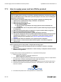
5. Supply power to the DynaGATE 10-12 respecting all safety instructions.
For more information see: "Power supply. How to turn ON/OFF and reset the product" on page101
6. Start developing your IoT applications.
The DynaGATE 10-12 supports the Eurotech Everyware Software Framework (ESF). ESF is a
smart application container that enables remote management of IoT gateways and provides a wide
range of APIs allowing you to write and deploy your own IoT application.
For more information see:
l "Eurotech Everyware IoT" on page93
l http://esf.eurotech.com/docs.
3 / 114

(This page has been intentionally left blank)

DynaGATE 10-12 User manual Rev. 2-0 Contents
CONTENTS
Trademarks 2
Intended audience of this document 2
Revision history 2
How to get started 3
Contents 5
1 Safety instructions 9
1.1 Warning messages 9
1.1.1 Warning messages for harm to persons 9
1.1.2 Warning messages for damage to property 10
1.2 Warning: power supply safety 10
1.3 Caution: wireless safety 10
1.4 Caution: product's surfaces may become hot 10
2 Consignes de securite 11
2.1 Messages d’avertissement 11
2.1.1 Messages d’avertissement relatifs au dommage aux personnes 11
2.1.2 Messages d’avertissement relatifs aux dommages matériels 12
2.2 Avertissement: sécurité de l’alimentation électrique 12
2.3 Attention: sécurité sur la connectivité sans fil 12
2.4 Attention: les surfaces du produit peuvent devenir chaudes 13
3 How to receive technical assistance 15
3.1 How to ask for technical support 15
3.2 How to send a product for repair 15
4 Comment obtenir une assistance technique 17
4.1 Comment contacter le support technique 17
4.2 Comment retourner un produit en service après vente 17
5 Conventions used 19
5.1 Conventions for signal names 19
5.2 Conventions for signal types 19
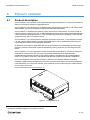
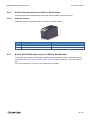
6 Product overview 21
6.1 Product description 21
6.2 Intended use and not allowed uses of the product 22
6.2.1 Intended use 22
6.2.2 Not allowed uses 22
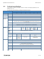
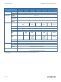
6.3 Technical specifications 23
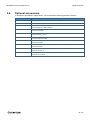
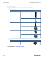
6.4 Optional accessories 25
6.5 Product labels 27
7 Regulatory information 29
7.1 CE marking 29
7.1.1 Safety 29
7.1.2 Packaging and packaging waste 29
7.1.3 Product disposal and recycling 29
7.1.4 WEEE compliance 29
7.1.5 RoHS 3 compliance 30
7.1.6 Directive RED 2014/53/EU 30
7.2 Statement for class A equipment (vers.: -61) 31
7.3 Statement for KN 32/35 (vers.: -61) 31
5 / 114

Contents DynaGATE 10-12 User manual Rev. 2-0
7.4 FCC/ISEDRegulatory Notices 32
7.4.1 FCC marking 32
7.4.2 FCC Class B Digital Device Notice 32
7.4.3 FCC restrictions on 5 GHz Wi-Fi usage 33
7.4.4 ISED Canada Regulatory Notices 34
7.4.5 ISED Class B Digital Device Notice 34
7.4.6 RF Radiation Exposure Statement 34
7.4.7 Labeling Information 34
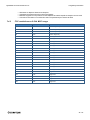
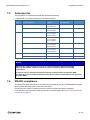
7.5 Antennas list 35
7.6 REACH compliance 35
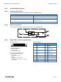
8 Interfaces overview 37
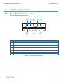
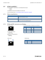
8.1 Front Side Interfaces overview 37
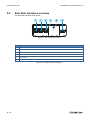
8.2 Rear Side Interfaces overview 38
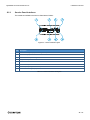
8.2.1 Service Panel Interfaces 39
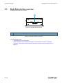
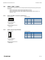
8.3 Right Side Interface overview 40
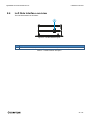
8.4 Left Side Interface overview 41
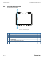
8.5 LED Indicators overview 42
9 Interfaces in detail 43
9.1 Wi-Fi and Bluetooth (all vers. except: -61, -63, -64) 43
9.1.1 Wi-Fi specifications 43
9.1.2 Bluetooth specifications 44
9.1.3 BLE specifications 44
9.1.4 Antennas connectors specifications 44
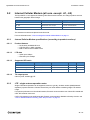
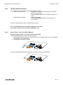
9.2 Internal Cellular Modem (all vers. except: -61, -62) 45
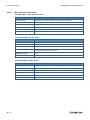
9.2.1 Internal Cellular Modem specifications (according to product versions) 45
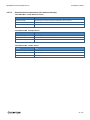
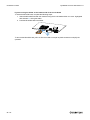
9.2.2 LTE - single antenna operation notes 45
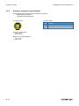
9.2.3 Antennas connectors specifications 48
9.2.4 The MicroSIM card holders 49
9.3 Internal GNSS 51
9.3.1 Internal GNSS specifications 51
9.3.2 Antenna connector specifications 51
9.4 Digital I/Os 52
9.4.1 Insulated Digital Inputs 52
9.4.2 Insulated Digital Outputs 53
9.4.3 Digital I/Os connector specifications 53
9.5 COM 0 and COM 1 54
9.5.1 Note for termination resistors for COM 0 in RS-485 mode 54
9.5.2 Note for termination resistors for COM 1 in RS-485 mode 54
9.5.3 Note for fail-safe resistors for COM 0 in RS-485 mode 54
9.5.4 Note for fail-safe resistors for COM 1 in RS-485 mode 55
9.5.5 Note for RS-485 half duplex (only for COM 0 in RS-485 mode) 55
9.5.6 COM 0 and COM 1 connector specifications 56
9.6 CAN 0 and CAN 1 57
9.6.1 CAN 0 and CAN 1 connector specifications 57
9.7 ETH 0 and ETH 1 58
9.7.1 Ethernet specifications 58
9.7.2 ETH 0 and ETH 1 connectors specifications 58
9.8 USB 0, USB 1, USB 2 59
9.8.1 USB 0 and USB 1 connectors specifications 59
9.8.2 USB 2 connector specifications 59
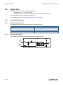
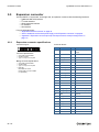
9.9 Expansion connector 60
9.9.1 Expansion connector specifications 60
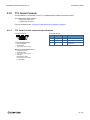
9.10 TTL Serial Console 61
9.10.1 TTL Serial Console connector specifications 61
6 / 114

DynaGATE 10-12 User manual Rev. 2-0 Contents
9.11 MicroSD card holder 62
9.11.1 How to insert / remove the MicroSD card in the holder 62
9.12 RTC (Real Time Clock) 63
9.12.1 The RTC Device "/dev/rtc1" 63
9.12.2 The RTC backup supercap 63
9.13 Watchdog 63
9.14 Accelerometer and Gyroscope 63
9.15 Programmable pushbutton 63
10 The Software 65
10.1 The Linux OS distribution 65
10.2 The bootloader procedure 65
10.3 How to create and use a bootable MicroSD card for a Linux release 65
10.4 The TPM 65
11 How to login the Administration Console 67
11.1 Default credentials 67
11.2 How to login using the Serial Console 67
11.3 How to Login Via Secure Shell (SSH) 67
11.3.1 How to Login Via eth0 68
11.3.2 How to Login via eth1 68
11.4 How to change the password 68
12 How to manage interfaces in Linux 69
12.1 How to drive the GPIOs: the GPIO Utility 69
12.2 How to determine the version of Linux installed 70
12.3 How the storage memory is exposed 70
12.4 How to manage Wi-Fi and Bluetooth 70
12.5 How to manage the Internal Cellular Modem 71
12.5.1 How to select the MicroSIM card holder to use 71
12.5.2 Note for LE910-NA1 Modem: AT&T / Verizon firmware support 71
12.5.3 How to disable/enable the diversity (CELL DIV) function 72
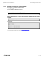
12.6 How to manage the Internal GNSS 73
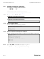
12.7 How to manage the CAN ports 74
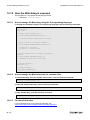
12.7.1 How to enable the CAN Bus 5V 74
12.7.2 How to setup a CAN port 74
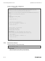
12.7.3 How to send/receive a message via a CAN port 74
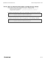
12.8 How the TTL Serial Console is exposed 74
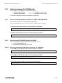
12.9 How to manage the COM ports 75
12.9.1 How to set the termination resistors for COM 0 in RS-485 mode 75
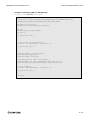
12.9.2 How to set the RS-422/485 modes for COM 0 75
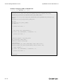
12.9.3 How to set the RS-232/485 modes for COM 1 79
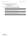
12.9.4 How to test a serial port 82
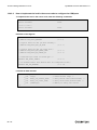
12.10 How to manage the Digital I/Os 83
12.11 How to manage the LED Indicators 83
12.12 How the Ethernet ports are exposed 83
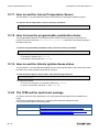
12.13 How to enable the 3.3V and 5V power supply on the Expansion connector 84
12.14 How the RTC is exposed 85
12.15 How the Watchdog is exposed 86
12.15.1 How to manage the Watchdog using the C programming language 86
12.15.2 How to manage the Watchdog from the command line 86
12.15.3 For more information 86
12.16 How to output Accelerometer and Gyroscope values 87
12.17 How to read the Internal Temperature Sensor 88
12.18 How to know the programmable pushbutton status 88
12.19 How to read the Vehicle Ignition Sense status 88
7 / 114

Contents DynaGATE 10-12 User manual Rev. 2-0
12.20 The TPM and the tpm2-tools package 88
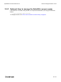
12.21 Optional: How to manage the ReliaCELL power supply 89
13 How to compile custom software 91
13.1 How to setup the toolchain 91
13.2 How to use the toolchain to compile custom software 91
14 Eurotech Everyware IoT 93
14.1 Everyware Software Framework (ESF) 93
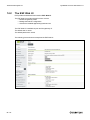
14.2 The ESF Web UI 94
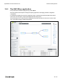
14.3 The ESF Wires application 95
14.4 Everyware Cloud (EC) 96
14.5 For more information 96
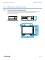
15 Mechanical specifications 97
15.1 Product mechanical dimensions 97
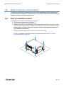
16 How to install the product 99
16.1 How to install the product 99
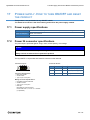
17 Power supply. How to turn ON/OFF and reset the product 101
17.1 Power supply specifications 101
17.2 Power IN connector specifications 101
17.3 How to supply power and turn ON the product 102
17.3.1 Note about the Vehicle Ignition Sense 103
17.4 How to turn OFF the product 103
17.5 How to reduce the power consumption of the product 103
17.6 How to hardware reset the product 103
18 How to maintain the product 105
18.1 How to safely remove the power supply 105
18.2 How to verify the installation of the product 105
18.3 How to clean the product 105
Appendix 1: Advanced boot options 107
1.1 Advanced boot options availability 107
1.1.1 How to configure a boot option 107
1.1.2 How to gain access to the Bootloader CLI 107
1.1.3 How to change the default boot option 108
1.2 The production fitImage 108
1.2.1 How to define the variants 108
1.2.2 How to manually configure the system to boot from a different DTB within the current fitImage 108
Appendix 2: Expansion connector pin map with respect to device tree pin assignment 111
Notes 113
8 / 114

DynaGATE 10-12 User manual Rev. 2-0 1 Safety instructions
1 SAFETY INSTRUCTIONS
IMPORTANT: Read carefully and understand the instructions and warnings contained in this
document before installing / using the product. Keep this document for future reference.
To lower the risk of personal injury, electric shock, fire or damage to equipment, observe the instructions
and warnings contained in this document.
Failure to comply with the instructions and warnings contained in this document, violates the standards of
safety, design, manufacture, and intended use of the product.
Eurotech assume no liability for any damage caused by failure to observe the instructions and warnings
contained in this document.
Whenever you have any doubt regarding the correct understanding of this document, contact the Eurotech
Technical Support (for more information see "How to receive technical assistance" on page15).
1.1 Warning messages
1.1.1 Warning messages for harm to persons
To indicate an imminently hazardous situation which, if not avoided, will result in death or serious injury,
the following message is used:
DANGER
Sign
(if necessary)
TEXT THAT EXPLAINS THE HAZARD AND THE CONSEQUENCES OF NOT
AVOIDING IT.
Text that explains how to avoid this hazard.
To indicate a potentially hazardous situation which, if not avoided, could result in death or serious injury,
the following message is used:
WARNING
Sign
(if necessary)
TEXT THAT EXPLAINS THE HAZARD AND THE CONSEQUENCES OF NOT
AVOIDING IT.
Text that explains how to avoid this hazard.
To indicate a potentially hazardous situation which, if not avoided, could result in minor or moderate injury,
the following message is used:
CAUTION
Sign
(if necessary)
TEXT THAT EXPLAINS THE HAZARD AND THE CONSEQUENCES OF NOT
AVOIDING IT.
Text that explains how to avoid this hazard.
9 / 114

1 Safety instructions DynaGATE 10-12 User manual Rev. 2-0
1.1.2 Warning messages for damage to property
To indicate potential risks of damage to the supported product (or to other property), the following message
is used:
NOTICE
Sign
(if necessary)
Text that explains how to avoid damaging the supported product (or other
property)
1.2 Warning: power supply safety
WARNING
ELECTRIC SHOCK HAZARD
Failure to supply power correctly or to follow all operating instructions correctly, may create an
electric shock hazard, which could result in personal injury or loss of life, and / or damage the
equipment or other property.
To avoid injuries and safely supply power to the product, complete the following steps:
1. Observe all the instructions for safety, installation, and operation
2. Make sure your hands are dry
3. Make sure that all the cables to use:
a. Are in good condition
b. Meet the product requirements and comply with the relevant standards and
regulations
4. Position cables with care. Do not position cables in places where they may be trampled
or compressed
5. Make sure that the power-points and plugs are in good condition before using them
6. Do not overload the power-points and plugs
7. Make sure that the product maintains a proper grounding connection
8. Use a power supply that meets the product requirements and complies with the relevant
standards and regulations. In case of uncertainties, contact the Eurotech Technical
Support Team (for more information see "How to receive technical assistance" on
page15)
9. Connect power after the installation of the system has been completed
10. Never connect or disconnect the cables with the system or the external apparatus
switched ON.
1.3 Caution: wireless safety
CAUTION
The antennas used with the product must be installed with care, avoiding any interference with
other electronic devices and keeping a distance from persons greater than 20 cm. If these
requirements cannot be satisfied, the system integrator has to assess the final product with
respect to SAR regulations.
1.4 Caution: product's surfaces may become hot
Depending on the operating environment temperature, product's surfaces may become hot, creating a burn
hazard. Always allow the product's surfaces to cool before touching them.
10 / 114

DynaGATE 10-12 User manual Rev. 2-0 2 Consignes de securite
2 CONSIGNES DE SECURITE
IMPORTANT: Lire attentivement et bien respecter les instructions et les avertissements contenus
dans ce document avant d'installer / d'utiliser le produit. Conserver ce document pour s'y référer
à l'avenir.
Pour éviter les risques de blessures, de choc électrique, d'incendie ou de détérioration du matériel, bien
suivre les instructions et les avertissements contenus dans ce document.
Le non-respect des instructions et des avertissements contenus dans ce document constitue une violation
des normes de sécurité, de conception, de fabrication et d'utilisation prévue du produit.
Eurotech rejette toute responsabilité pour les dommages causés en cas de non-respect des instructions et
des avertissements contenus dans ce document.
En cas de doute sur la compréhension de ce document, contacter le Support Technique d’ Eurotech (pour
plus d’informations voir "Comment obtenir une assistance technique" page 17).
2.1 Messages d’avertissement
2.1.1 Messages d’avertissement relatifs au dommage aux personnes
Pour signaler une situation dangereuse imminente qui, si elle n’est pas évitée, entraînera la mort ou un
préjudice grave le message suivant est utilisé:
DANGER
Signal
(si besoin)
TEXTE EXPLIQUANT LE DANGER ET SES CONSÉQUENCES.
Texte expliquant comment éviter ce danger.
Pour signaler une situation potentiellement dangereuse qui, si elle n’est pas évitée, pourrait entraîner la
mort ou un préjudice grave le message suivant est utilisé:
AVERTISSEMENT
Signal
(si besoin)
TEXTE EXPLIQUANT LE DANGER ET SES CONSÉQUENCES.
Texte expliquant comment éviter ce danger.
Pour signaler une situation potentiellement dangereuse qui, si elle n’est pas évitée, pourrait entraîner un
préjudice mineur ou modéré le message suivant est utilisé:
ATTENTION
Signal
(si besoin)
TEXTE EXPLIQUANT LE DANGER ET SES CONSÉQUENCES.
Texte expliquant comment éviter ce danger.
11 / 114

2 Consignes de securite DynaGATE 10-12 User manual Rev. 2-0
2.1.2 Messages d’avertissement relatifs aux dommages matériels
Pour signaler les risques potentiels de détérioration du produit (ou des produits annexes), le message
suivant est utilisé:
AVIS
Signal
(si besoin)
Texte expliquant comment éviter d'endommager le produit (ou des produits
annexes)
2.2 Avertissement: sécurité de l’alimentation électrique
AVERTISSEMENT
RISQUE DE CHOC ÉLECTRIQUE
Une alimentation électrique incorrecte peut créer un risque de choc électrique, pouvant
entraîner des blessures corporelles ou la perte de vies humaines, et / ou endommager le
produit ou d'autres biens.
Pour éviter les blessures et brancher l'appareil en toute sécurité, procéder comme suit:
1. Respecter toutes les consignes de sécurité, d'installation et d'utilisation
2. S'assurer que les mains sont sèches
3. S'assurer que tous les câbles utilisés:
a. Sont en bon état
b. Répondent aux exigences du produit et soient conformes aux normes et
réglementations en vigueur
4. Positionner les câbles avec soin. Ne pas les placer dans des endroits où ils risquent
d'être piétinés ou comprimés
5. S’assurer que les prises de courant et les connecteurs d’alimentation sont en bon état
avant de les utiliser
6. Ne pas surcharger les prises de courant et les connecteurs d’alimentation
7. S'assurer que le produit est correctement relié à la terre
8. Utiliser une alimentation électrique conforme aux exigences du produit et conforme aux
normes et réglementations en vigueur. En cas d'incertitude, contacter l'équipe
d'assistance technique d'Eurotech (pour plus d'informations, voir "Comment obtenir une
assistance technique" page 17)
9. Ne Brancher l'alimentation électrique qu’une fois l'installation du système terminée
10. Ne jamais brancher ou débrancher les câbles lorsque le système ou un appareil
périphérique sous tension.
2.3 Attention: sécurité sur la connectivité sans fil
ATTENTION
Les antennes utilisées avec le produit doivent être installées avec soin, en évitant toute
interférence avec d'autres appareils électroniques et à au moins 20 cm des personnes. Si ces
exigences ne peuvent être satisfaites, l'intégrateur du système doit évaluer le produit final par
rapport à la réglementation SAR.
12 / 114

DynaGATE 10-12 User manual Rev. 2-0 2 Consignes de securite
2.4 Attention: les surfaces du produit peuvent devenir chaudes
Selon la température ambiante lors de l’utilisation, les surfaces du produit peuvent devenir brûlantes,
engendrant un risque de brûlure. Laisser toujours les surfaces du produit refroidir avant de les
toucher.
13 / 114

(This page has been intentionally left blank)

DynaGATE 10-12 User manual Rev. 2-0 3 How to receive technical assistance
3 HOW TO RECEIVE TECHNICAL ASSISTANCE
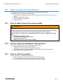
3.1 How to ask for technical support
To ask for technical support, complete the following steps
1. Go to the Eurotech Global Support Centre: https://support.eurotech.com/
2. Submit a support request
3. Wait for the reply from the Support Team with the information you required
3.2 How to send a product for repair
Any product returned to Eurotech, that is found to be damaged due to inadequate packaging, will
not be covered by the warranty.
To send a product for repair, complete the following steps:
1. Go to the Eurotech Global Support Centre: https://support.eurotech.com/
2. Submit an RMA request
3. Wait for the reply from the RMA Department. It will contain:
l The RMA number
l The shipping information
4. Pack the product adequately using anti-static material and place it in a sturdy box with enough
packing material to protect it from shocks and vibrations
5. Ship the product to Eurotech following the information received from the RMA Department.
15 / 114

(This page has been intentionally left blank)

DynaGATE 10-12 User manual Rev. 2-0 4 Comment obtenir une assistance technique
4 COMMENT OBTENIR UNE ASSISTANCE TECHNIQUE
4.1 Comment contacter le support technique
Pour demander un support technique, procéder comme suit:
1. Se connecter au Support Eurotech sur: https://support.eurotech.com/
2. Envoyer une demande d’assistance
3. Attendre la réponse de l'équipe de support avec les informations requises
4.2 Comment retourner un produit en service après vente
Tout produit renvoyé à Eurotech, qui se trouve endommagé en raison d'un emballage inadéquat,
ne sera pas couvert par la garantie.
Pour retourner un produit en Service Après Vente, procéder comme suit:
1. Se connecter au Support Eurotech sur: https://support.eurotech.com/
2. Faire une demande de RMA
3. Attendre la réponse du service RMA qui indiquera:
l Le numéro de RMA
l Les informations pour l’expédition
4. Emballer le produit de manière adéquate en utilisant des protections antistatiques et le placer dans
un conditionnement solide contenant suffisamment de matériau d'emballage pour le protéger des
chocs et des vibrations
5. Expédier le produit chez Eurotech selon les informations reçues par mail.
17 / 114

(This page has been intentionally left blank)

DynaGATE 10-12 User manual Rev. 2-0 5 Conventions used
5 CONVENTIONS USED
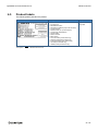
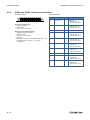
5.1 Conventions for signal names
Convention Description
GND Ground
# Active low signal
+ Positive signal; Positive signal in differential pair
- Negative signal; Negative signal in differential pair
3.3 3.3 V signal level
5 5 V signal level
NC No Connection
Reserved Use is reserved to Eurotech
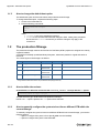
5.2 Conventions for signal types
Convention Description
I Signal is an input to the system
O Signal is an output from the system
IO Signal may be input or output
P Power and Ground
A Analog signal
NC No Connection
Reserved Use is reserved to Eurotech
19 / 114

(This page has been intentionally left blank)
La page est en cours de chargement...
La page est en cours de chargement...
La page est en cours de chargement...
La page est en cours de chargement...
La page est en cours de chargement...
La page est en cours de chargement...
La page est en cours de chargement...
La page est en cours de chargement...
La page est en cours de chargement...
La page est en cours de chargement...
La page est en cours de chargement...
La page est en cours de chargement...
La page est en cours de chargement...
La page est en cours de chargement...
La page est en cours de chargement...
La page est en cours de chargement...
La page est en cours de chargement...
La page est en cours de chargement...
La page est en cours de chargement...
La page est en cours de chargement...
La page est en cours de chargement...
La page est en cours de chargement...
La page est en cours de chargement...
La page est en cours de chargement...
La page est en cours de chargement...
La page est en cours de chargement...
La page est en cours de chargement...
La page est en cours de chargement...
La page est en cours de chargement...
La page est en cours de chargement...
La page est en cours de chargement...
La page est en cours de chargement...
La page est en cours de chargement...
La page est en cours de chargement...
La page est en cours de chargement...
La page est en cours de chargement...
La page est en cours de chargement...
La page est en cours de chargement...
La page est en cours de chargement...
La page est en cours de chargement...
La page est en cours de chargement...
La page est en cours de chargement...
La page est en cours de chargement...
La page est en cours de chargement...
La page est en cours de chargement...
La page est en cours de chargement...
La page est en cours de chargement...
La page est en cours de chargement...
La page est en cours de chargement...
La page est en cours de chargement...
La page est en cours de chargement...
La page est en cours de chargement...
La page est en cours de chargement...
La page est en cours de chargement...
La page est en cours de chargement...
La page est en cours de chargement...
La page est en cours de chargement...
La page est en cours de chargement...
La page est en cours de chargement...
La page est en cours de chargement...
La page est en cours de chargement...
La page est en cours de chargement...
La page est en cours de chargement...
La page est en cours de chargement...
La page est en cours de chargement...
La page est en cours de chargement...
La page est en cours de chargement...
La page est en cours de chargement...
La page est en cours de chargement...
La page est en cours de chargement...
La page est en cours de chargement...
La page est en cours de chargement...
La page est en cours de chargement...
La page est en cours de chargement...
La page est en cours de chargement...
La page est en cours de chargement...
La page est en cours de chargement...
La page est en cours de chargement...
La page est en cours de chargement...
La page est en cours de chargement...
La page est en cours de chargement...
La page est en cours de chargement...
La page est en cours de chargement...
La page est en cours de chargement...
La page est en cours de chargement...
La page est en cours de chargement...
La page est en cours de chargement...
La page est en cours de chargement...
La page est en cours de chargement...
La page est en cours de chargement...
La page est en cours de chargement...
La page est en cours de chargement...
La page est en cours de chargement...
La page est en cours de chargement...
-
 1
1
-
 2
2
-
 3
3
-
 4
4
-
 5
5
-
 6
6
-
 7
7
-
 8
8
-
 9
9
-
 10
10
-
 11
11
-
 12
12
-
 13
13
-
 14
14
-
 15
15
-
 16
16
-
 17
17
-
 18
18
-
 19
19
-
 20
20
-
 21
21
-
 22
22
-
 23
23
-
 24
24
-
 25
25
-
 26
26
-
 27
27
-
 28
28
-
 29
29
-
 30
30
-
 31
31
-
 32
32
-
 33
33
-
 34
34
-
 35
35
-
 36
36
-
 37
37
-
 38
38
-
 39
39
-
 40
40
-
 41
41
-
 42
42
-
 43
43
-
 44
44
-
 45
45
-
 46
46
-
 47
47
-
 48
48
-
 49
49
-
 50
50
-
 51
51
-
 52
52
-
 53
53
-
 54
54
-
 55
55
-
 56
56
-
 57
57
-
 58
58
-
 59
59
-
 60
60
-
 61
61
-
 62
62
-
 63
63
-
 64
64
-
 65
65
-
 66
66
-
 67
67
-
 68
68
-
 69
69
-
 70
70
-
 71
71
-
 72
72
-
 73
73
-
 74
74
-
 75
75
-
 76
76
-
 77
77
-
 78
78
-
 79
79
-
 80
80
-
 81
81
-
 82
82
-
 83
83
-
 84
84
-
 85
85
-
 86
86
-
 87
87
-
 88
88
-
 89
89
-
 90
90
-
 91
91
-
 92
92
-
 93
93
-
 94
94
-
 95
95
-
 96
96
-
 97
97
-
 98
98
-
 99
99
-
 100
100
-
 101
101
-
 102
102
-
 103
103
-
 104
104
-
 105
105
-
 106
106
-
 107
107
-
 108
108
-
 109
109
-
 110
110
-
 111
111
-
 112
112
-
 113
113
-
 114
114


Eurotech DynaGATE 10-12 Le manuel du propriétaire
- Taper
- Le manuel du propriétaire
dans d''autres langues
Documents connexes
-
Eurotech DynaGATE 10-12 Le manuel du propriétaire
-
-
-
-
-
Eurotech ReliaGATE 10-12 Le manuel du propriétaire
-
-
-
-
Eurotech ReliaGATE 10-20 Le manuel du propriétaire
Autres documents
-
Cirago BTA3310 Fiche technique
-
Shenzhen Omni Intelligent Technology G3 IoT Device Manuel utilisateur
-
Telit Wireless Solutions xE910 Manuel utilisateur
-
-
Audi Scon2 Mode d'emploi
-
Honeywell AlarmNet CELL-ANTHB Guide d'installation
-
Hach SC4200c Basic User Manual
-
Fibocom SC126-W Mode d'emploi
-
Hyundai Mobis ECU BDC-4E03 Smart Key Mode d'emploi
-