Allen-Bradley E300 Installation Instructions Manual
- Taper
- Installation Instructions Manual

Installation Instructions
Original Instructions
E300 Electronic Overload Relay
Bulletin Numbers
193, 592
Topic Page
North American Hazardous Location Approval 3
Introduction 4
Before You Begin 4
What You Need 5
Assemble the E300 Relay 5
Wire the E300 Relay 7
Set the IP Address 9
E300 Configuration via Rotary Dial Addressing 9
E300 Relay Configuration via the BOOTP/ DHCP Utility 10
Downloading the Electronic Data Sheet (EDS) File 13
Additional Resources 16

2 Rockwell Automation Publication 193-IN080A-EN-P - September 2018
E300 Electronic Overload Relay
ATTENTION: Read this document and the documents listed in the Additional Resources section about installation, configuration and operation of this equipment before you install, configure, operate or
maintain this product. Users are required to familiarize themselves with installation and wiring instructions in addition to requirements of all applicable codes, laws, and standards.
Activities including installation, adjustments, putting into service, use, assembly, disassembly, and maintenance are required to be carried out by suitably trained personnel in accordance with applicable code
of practice.
If this equipment is used in a manner not specified by the manufacturer, the protection provided by the equipment may be impaired.
注意:在安装、配置、操作和维护本产品前,请阅读本文档以及 “ 其他资源 ” 部分列出的有关设备安装、配置和操作的相应文档。除了所有适用规范、法
律和标准的相关要求之外,用户还必须熟悉安装和接线说明。
安装、调整、投运、使用、组装、拆卸和维护等各项操作必须由经过适当训练的专业人员按照适用的操作规范实施。
如果未按照制造商指定的方式使用该设备,则可能会损害设备提供的保护。
ATENCIÓN: Antes de instalar, configurar, poner en funcionamiento o realizar el mantenimiento de este producto, lea este documento y los documentos listados en la sección Recursos adicionales acerca de la
instalación, configuración y operación de este equipo. Los usuarios deben familiarizarse con las instrucciones de instalación y cableado y con los requisitos de todos los códigos, leyes y estándares vigentes.
El personal debidamente capacitado debe realizar las actividades relacionadas a la instalación, ajustes, puesta en servicio, uso, ensamblaje, desensamblaje y mantenimiento de conformidad con el código de
práctica aplicable.
Si este equipo se usa de una manera no especificada por el fabricante, la protección provista por el equipo puede resultar afectada.
ATENÇÃO: Leia este e os demais documentos sobre instalação, configuração e operação do equipamento que estão na seção Recursos adicionais antes de instalar, configurar, operar ou manter este produto. Os
usuários devem se familiarizar com as instruções de instalação e fiação além das especificações para todos os códigos, leis e normas aplicáveis.
É necessário que as atividades, incluindo instalação, ajustes, colocação em serviço, utilização, montagem, desmontagem e manutenção sejam realizadas por pessoal qualificado e especializado, de acordo com o
código de prática aplicável.
Caso este equipamento seja utilizado de maneira não estabelecida pelo fabricante, a proteção fornecida pelo equipamento pode ficar prejudicada.
ВНИМАНИЕ: Перед тем как устанавливать, настраивать, эксплуатировать или обслуживать данное оборудование, прочитайте этот документ и документы, перечисленные в разделе
«Дополнительные ресурсы». В этих документах изложены сведения об установке, настройке и эксплуатации данного оборудования. Пользователи обязаны ознакомиться с инструкциями по
установке и прокладке соединений, а также с требованиями всех применимых норм, законов и стандартов.
Все действия, включая установку, наладку, ввод в эксплуатацию, использование, сборку, разборку и техническое обслуживание, должны выполняться обученным персоналом в соответствии с
применимыми нормами и правилами.
Если оборудование используется не предусмотренным производителем образом, защита оборудования может быть нарушена.
注意 : 本製品を設置、構成、稼動または保守する前に、本書および本機器の設置、設定、操作についての参考資料の該当箇所に記載されている文書に目
を通してください。ユーザは、すべての該当する条例、法律、規格の要件に加えて、設置および配線の手順に習熟している必要があります。
設置調整、運転の開始、使用、組立て、解体、保守を含む諸作業は、該当する実施規則に従って訓練を受けた適切な作業員が実行する必要があります。
本機器が製造メーカにより指定されていない方法で使用されている場合、機器により提供されている保護が損なわれる恐れがあります。
ACHTUNG: Lesen Sie dieses Dokument und die im Abschnitt „Weitere Informationen“aufgeführten Dokumente, die Informationen zu Installation, Konfiguration und Bedienung dieses Produkts enthalten,
bevor Sie dieses Produkt installieren, konfigurieren, bedienen oder warten. Anwender müssen sich neben den Bestimmungen aller anwendbaren Vorschriften, Gesetze und Normen zusätzlich mit den
Installations- und Verdrahtungsanweisungen vertraut machen.
Arbeiten im Rahmen der Installation, Anpassung, Inbetriebnahme, Verwendung, Montage, Demontage oder Instandhaltung dürfen nur durch ausreichend geschulte Mitarbeiter und in Übereinstimmung mit
den anwendbaren Ausführungsvorschriften vorgenommen werden.
Wenn das Gerät in einer Weise verwendet wird, die vom Hersteller nicht vorgesehen ist, kann die Schutzfunktion beeinträchtigt sein.
ATTENTION : Lisez ce document et les documents listés dans la section Ressources complémentaires relatifs à l’installation, la configuration et le fonctionnement de cet équipement avant d’installer,
configurer, utiliser ou entretenir ce produit. Les utilisateurs doivent se familiariser avec les instructions d’installation et de câblage en plus des exigences relatives aux codes, lois et normes en vigueur.
Les activités relatives à l’installation, le réglage, la mise en service, l’utilisation, l’assemblage, le démontage et l’entretien doivent être réalisées par des personnes formées selon le code de pratique en vigueur.
Si cet équipement est utilisé d’une façon qui n’a pas été définie par le fabricant, la protection fournie par l’équipement peut être compromise.
주의 : 본 제품 설치 , 설정 , 작동 또는 유지 보수하기 전에 본 문서를 포함하여 설치 , 설정 및 작동에 관한 참고 자료 섹션의 문서들을 반드시 읽고 숙지하
십시오 . 사용자는 모든 관련 규정 , 법규 및 표준에서 요구하는 사항에 대해 반드시 설치 및 배선 지침을 숙지해야 합니다 .
설치 , 조정 , 가동 , 사용 , 조립 , 분해 , 유지보수 등 모든 작업은 관련 규정에 따라 적절한 교육을 받은 사용자를 통해서만 수행해야 합니다 .
본 장비를 제조사가 명시하지 않은 방법으로 사용하면 장비의 보호 기능이 손상될 수 있습니다 .
ATTENZIONE Prima di installare, configurare ed utilizzare il prodotto, o effettuare interventi di manutenzione su di esso, leggere il presente documento ed i documenti elencati nella sezione “Altre risorse”,
riguardanti l’installazione, la configurazione ed il funzionamento dell’apparecchiatura. Gli utenti devono leggere e comprendere le istruzioni di installazione e cablaggio, oltre ai requisiti previsti dalle leggi,
codici e standard applicabili.
Le attività come installazione, regolazioni, utilizzo, assemblaggio, disassemblaggio e manutenzione devono essere svolte da personale adeguatamente addestrato, nel rispetto delle procedure previste.
Qualora l’apparecchio venga utilizzato con modalità diverse da quanto previsto dal produttore, la sua funzione di protezione potrebbe venire compromessa.
DİKKAT: Bu ürünün kurulumu, yapılandırılması, işletilmesi veya bakımı öncesinde bu dokümanı ve bu ekipmanın kurulumu, yapılandırılması ve işletimi ile ilgili İlave Kaynaklar bölümünde yer listelenmiş
dokümanları okuyun. Kullanıcılar yürürlükteki tüm yönetmelikler, yasalar ve standartların gereksinimlerine ek olarak kurulum ve kablolama talimatlarını da öğrenmek zorundadır.
Kurulum, ayarlama, hizmete alma, kullanma, parçaları birleştirme, parçaları sökme ve bakım gibi aktiviteler sadece uygun eğitimleri almış kişiler tarafından yürürlükteki uygulama yönetmeliklerine uygun
şekilde yapılabilir.
Bu ekipman üretici tarafından belirlenmiş amacın dışında kullanılırsa, ekipman tarafından sağlanan koruma bozulabilir.
注意事項:在安裝、設定、操作或維護本產品前,請先閱讀此文件以及列於 「其他資源」章節中有關安裝、設定與操作此設備的文件。使用者必須熟悉安裝
和配線指示,並符合所有法規、法律和標準要求。
包括安裝、調整、交付使用、使用、組裝、拆卸和維護等動作都必須交由已經過適當訓練的人員進行,以符合適用的實作法規。
如果將設備用於非製造商指定的用途時,可能會造成設備所提供的保護功能受損。
POZOR: Než začnete instalovat, konfigurovat či provozovat tento výrobek nebo provádět jeho údržbu, přečtěte si tento dokument a dokumenty uvedené v části Dodatečné zdroje ohledně instalace, konfigurace
a provozu tohoto zařízení. Uživatelé se musejí vedle požadavků všech relevantních vyhlášek, zákonů a norem nutně seznámit také s pokyny pro instalaci a elektrické zapojení.
Činnosti zahrnující instalaci, nastavení, uvedení do provozu, užívání, montáž, demontáž a údržbu musí vykonávat vhodně proškolený personál v souladu s příslušnými prováděcími předpisy.
Pokud se toto zařízení používá způsobem neodpovídajícím specifikaci výrobce, může být narušena ochrana, kterou toto zařízení poskytuje.
UWAGA: Przed instalacją, konfiguracją, użytkowaniem lub konserwacją tego produktu należy przeczytać niniejszy dokument oraz wszystkie dokumenty wymienione w sekcji Dodatkowe źródła omawiające
instalację, konfigurację i procedury użytkowania tego urządzenia. Użytkownicy mają obowiązek zapoznać się z instrukcjami dotyczącymi instalacji oraz oprzewodowania, jak również z obowiązującymi
kodeksami, prawem i normami.
Działania obejmujące instalację, regulację, przekazanie do użytkowania, użytkowanie, montaż, demontaż oraz konserwację muszą być wykonywane przez odpowiednio przeszkolony personel zgodnie z
obowiązującym kodeksem postępowania.
Jeśli urządzenie jest użytkowane w sposób inny niż określony przez producenta, zabezpieczenie zapewniane przez urządzenie może zostać ograniczone.
OBS! Läs detta dokument samt dokumentet, som står listat i avsnittet Övriga resurser, om installation, konfigurering och drift av denna utrustning innan du installerar, konfigurerar eller börjar använda eller
utföra underhållsarbete på produkten. Användare måste bekanta sig med instruktioner för installation och kabeldragning, förutom krav enligt gällande koder, lagar och standarder.
Åtgärder som installation, justering, service, användning, montering, demontering och underhållsarbete måste utföras av personal med lämplig utbildning enligt lämpligt bruk.
Om denna utrustning används på ett sätt som inte anges av tillverkaren kan det hända att utrustningens skyddsanordningar försätts ur funktion.
LET OP: Lees dit document en de documenten die genoemd worden in de paragraaf Aanvullende informatie over de installatie, configuratie en bediening van deze apparatuur voordat u dit product installeert,
configureert, bediend of onderhoudt. Gebruikers moeten zich vertrouwd maken met de installatie en de bedradingsinstructies, naast de vereisten van alle toepasselijke regels, wetten en normen.
Activiteiten zoals het installeren, afstellen, in gebruik stellen, gebruiken, monteren, demonteren en het uitvoeren van onderhoud mogen uitsluitend worden uitgevoerd door hiervoor opgeleid personeel en in
overeenstemming met de geldende praktijkregels.
Indien de apparatuur wordt gebruikt op een wijze die niet is gespecificeerd door de fabrikant, dan bestaat het gevaar dat de beveiliging van de apparatuur niet goed werkt.

Rockwell Automation Publication 193-IN080A-EN-P - September 2018 3
E300 Electronic Overload Relay
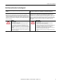
North American Hazardous Location Approval
The following information applies when operating this equipment in hazardous
locations.
Informations sur l’utilisation de cet équipement en environnements dangereux.
Products marked "CL I, DIV 2, GP A, B, C, D" are suitable for use in Class I Division 2 Groups A, B, C,
D, Hazardous Locations and nonhazardous locations only. Each product is supplied with
markings on the rating nameplate indicating the hazardous location temperature code. When
combining products within a system, the most adverse temperature code (lowest "T" number)
may be used to help determine the overall temperature code of the system. Combinations of
equipment in your system are subject to investigation by the local Authority Having Jurisdiction
at the time of installation.
Les produits marqués "CL I, DIV 2, GP A, B, C, D" ne conviennent qu'à une utilisation en
environnements de Classe I Division 2 Groupes A, B, C, D dangereux et non dangereux. Chaque
produit est livré avec des marquages sur sa plaque d'identification qui indiquent le code de
température pour les environnements dangereux. Lorsque plusieurs produits sont combinés dans un
système, le code de température le plus défavorable (code de température le plus faible) peut être
utilisé pour déterminer le code de température global du système. Les combinaisons d'équipements
dans le système sont sujettes à inspection par les autorités locales qualifiées au moment de
l'installation.
WARNING:
Explosion Hazard –
• Do not disconnect equipment unless power has been removed or the
area is known to be nonhazardous.
• Do not disconnect connections to this equipment unless power has
been removed or the area is known to be nonhazardous. Secure any
external connections that mate to this equipment by using screws,
sliding latches, threaded connectors, or other means provided with this
product.
• Substitution of components may impair suitability for Class I, Division 2.
• If this product contains batteries, they must only be changed in an area
known to be nonhazardous.
AVERTISSEMENT:
Risque d’Explosion –
• Couper le courant ou s'assurer que l'environnement est classé non
dangereux avant de débrancher l'équipement.
• Couper le courant ou s'assurer que l'environnement est classé non
dangereux avant de débrancher les connecteurs. Fixer tous les connecteurs
externes reliés à cet équipement à l'aide de vis, loquets coulissants,
connecteurs filetés ou autres moyens fournis avec ce produit.
• La substitution de composants peut rendre cet équipement inadapté à une
utilisation en environnement de Classe I, Division 2.
• S'assurer que l'environnement est classé non dangereux avant de changer
les piles.

4 Rockwell Automation Publication 193-IN080A-EN-P - September 2018
E300 Electronic Overload Relay
Introduction
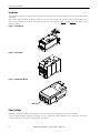
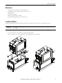
This publication explains how to assemble the three module types of the E300™ Electronic Overload Relay, wire the relay, and set the relay IP or
node address.
Three modules comprise the E300 relay. All three modules are required to make a functional overload relay. You can customize each of the three
with accessories to tailor the electronic motor overload for the exact needs of your application. Figure 1
through Figure 3 show the three types of
E300 relay modules.
Figure 1 - Sensing Module
Figure 2 - Control Module
Figure 3 - Communication Module
Before You Begin
Familiarize yourself with installation and wiring instructions and the requirements of all applicable codes, laws, and standards.
Activities including installation, adjustments, putting into service, use, assembly, disassembly, and maintenance are required to be carried out by
suitably trained personnel in accordance with applicable code of practice.

Rockwell Automation Publication 193-IN080A-EN-P - September 2018 5
E300 Electronic Overload Relay
What You Need
• E300 relay control, communication, and sensing modules
• Any additional modules required (operator station, contactor, etc.)
• Wiring diagram
• Thin flathead screwdriver
• Wire for I/O terminals, #12…24 AWG
• Standard industrial grade Ethernet or DeviceNet™ cable
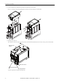
Assemble the E300 Relay
Complete the following steps to assemble the E300 relay. When you have finished, you will be ready to wire and configure the device.
1. Connect the E300 relay control module to the E300 relay sensing module.
Be sure to secure this connection by pushing in the tab on the right side of the control module.
IMPORTANT
Take caution while assembling each module and add-on component. Small I/O pins can bend and/or break, which causes a module service error once the
device is configured.
2
3
1

6 Rockwell Automation Publication 193-IN080A-EN-P - September 2018
E300 Electronic Overload Relay
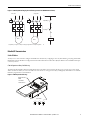
2. Connect the E300 relay communication module to the E300 relay control module.
Be sure to secure this connection by pushing in the tab shown on the left side of the control module.
3. Install the I/O connectors.
Two of the I/O connectors attach to the bottom of the control modules. The third connector attaches to the top of the control module.
You have completed the assembly of the E300 relay.
1
3
2
Relay/Ground Fault Terminals
Power / Input / PTC
Terminals
Expansion Bus Connector
Sensing Module Latch

Rockwell Automation Publication 193-IN080A-EN-P - September 2018 7
E300 Electronic Overload Relay
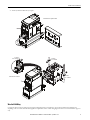
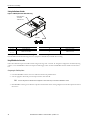
4. Attach any add-on modules that you require.
Wire the E300 Relay
Complete the device wiring according to the appropriate wiring diagrams for your application. You can wire the E300 relay in multiple ways,
depending on the accessories, add-on modules, application requirements, and so on. The wiring diagrams in this section are for illustrative purposes
only.
0
RESET
SELECT
ESC
REMOTE
LOC AL
Connection of an operator station
7 -11 lb•in
0.79 - 1.24 N•m
9 - 22 lb•in
1.01 - 2.48 N•m
5 - 7 lb•in
0.56 - 0.79 N•m
1
2
5
4
6
IN1
IN0
A2
A1
R04
R03
3
Connection of a contactor

8 Rockwell Automation Publication 193-IN080A-EN-P - September 2018
E300 Electronic Overload Relay
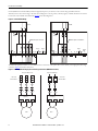
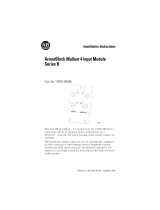
For the E300 Electronic Overload Relay to function properly and protect your motor, it needs a control voltage (24V DC, 120V AC,
240VAC).Connect the control voltage to the device by attaching wires to the A1 (positive) and A2 (negative) terminals, which are located on the
bottom of the control module of the E300 relay. Figure 4 shows this configuration.
Figure 4 - Control Module Wiring
The E300 relay typically is wired in one of two different motor connections: a three-phase, direct-on-line (DOL), and a single-phase, full-voltage
connection. Figure 5 shows these connections.
Figure 5 - E300 Relay DOL and Single-phase Full-voltage Connections (NEMA Nomenclature)
193-EIO…
193-EIOGP…
A1
Relay 0
IN1IN0A2R04R03
Additional Inputs for 193-EIO-63…
A1
Relay 0
IN1IN0A2R04R03
Additional Inputs for 193-EIOGP-63…
A1 A1 A2
Relay 1 Relay 2
(+) (-)
A1 A1
A2
(+) (-)
Relay 1
Ground
Fault
IN4IN3IN2 R13PEIN5 R24R23R14
IN3IN2 PE
+t°
IT2IT1
PTC
R13 S2S1R14
Three-phase Direct-on-Line
Single-phase Full Voltage
Short-circuit
Protection Device
Short-circuit
Protection Device
L1 L2 L3
E300 Relay E300 Relay
Motor Motor
2/T1 4/T2 6/T3
2/T1 4/T2 6/T3
T1
T2
T3
T1 T2
L1 L2

Rockwell Automation Publication 193-IN080A-EN-P - September 2018 9
E300 Electronic Overload Relay
Figure 6 - E300 Relay DOL and Single-phase Full-voltage Connections (CENELEC Nomenclature)
EtherNet/IP Communication
Set the IP Address
You may use one of two methods to configure the IP address for the E300 relay: configuring via the rotary dial addressing, or by using the BOOTP/
DHCP utility. After the IP address is configured, download and install the Electronic Data Sheet (EDS) for RSLinx® Classic and RSLinx Enterprise
connectivity software.
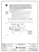
E300 Configuration via Rotary Dial Addressing
The E300 relay EtherNet/IP Communication Module has three node address selection switches that allow you to select the last octet for the IP
address 192.168.1.xxx. When you set the node address selection switches to a value greater than 255 (excluding 888), the IP address is set to DHCP
Enabled or programmed for a static IP address.
Figure 7 - E300 Relay Node Addressing
Three-phase
Single-phase
Motor
T1 T5T3
Motor
T1 T5T3
L1
N
A1
A2
K1
A1
A2
K1
153
153
264
264
A1
A2
K
R03
R04
R13
R14
Output Relay 0
Trip Relay 0
(1)
(1) Output Relay 1 is assigned as a normally closed trip relay using Parameter 203 9Output 1 Assignment).
x100
8
0
2
46
x10
8
0
2
46
x1
8
0
2
46
Network Information
-MAC ID
-Serial Number
-Firmware Revision
Node Address

10 Rockwell Automation Publication 193-IN080A-EN-P - September 2018
E300 Electronic Overload Relay
1. Verify that the E300 Relay is fully powered, then turn the three dials to your selected IP address.
2. Once dials are in place, cycle power to the E300 Relay.
For example, when the left dial is set to 0, the middle is set to 0, and the right dial is set to 6, the resulting IP address is: 192.168.1.006 or
192.168.1.6.
E300 Relay Configuration via the BOOTP/ DHCP Utility
By default, the E300 relay EtherNet/IP™ Communication Module is DHCP Enabled. The BOOTP/DHCP utility is a standalone program that is
included when you install RSLinx™ Classic software.
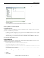
To assign an IP address to the E300 relay via the BOOTP/DHCP utility, perform the following procedure.
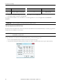
1. Execute the BOOTP/DHCP software and choose Tool, then select Network Settings.
2. Type the subnet mask, gateway address, primary/secondary server addresses, and domain name in their respective fields. Click OK.
Node Address Function Node Address Function
001…254 Set IP address to 192.168.1.xxx 888 Reset to factory defaults
255…887
889…999
Set IP address via DHCP or use static IP address 000 Administration mode
IMPORTANT
A power cycle is required for any rotary dial changes to the E300 Relay to take effect.
IMPORTANT
Before starting the BOOTP/DHCP utility, verify the hardware MAC ID, which is printed on the front of the E300 Relay Communication Module. The MAC ID has
a format similar to: 00-0b-db-14-55- 35.

Rockwell Automation Publication 193-IN080A-EN-P - September 2018 11
E300 Electronic Overload Relay
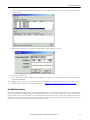
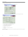
3. Double-click the MAC address of the E300 module that you want to configure. It may take a few seconds for your E300 relay to appear in
the Request History.
4. The New Entry window appears with the Ethernet Address (MAC). Type the IP address. Select OK.
5. Cycle power to the E300 relay.
6. Once your E300 is powered up, verify that the proper IP address has been assigned, select the module in the Relation List panel, and click
Disable BOOTP/DHCP.
After completing either one of the above methods, your E300 Electronic Overload Relay is configured and connected to your network. The next
step to communicating with the E300 is to download its EDS file. See See Downloading the Electronic Data Sheet (EDS) File
on page 13.
DeviceNet Communication
E300 relays are shipped with a default hardware node address (MAC ID) setting of 9-9 (node address 63) and the data rate set to Autobaud. Each
device on a DeviceNet network must have a unique node address, which can be set to a value from 0 to 63. Most DeviceNet systems use address 0 for
the master device (Scanner). Leave node address 63 vacant for introduction of new slave devices. You can change the node address and data rate for
E300 relays by using software or by setting the hardware switches that are on the front of each unit. While both methods yield the same result, it is a
good practice to choose one method and use it consistently throughout the system.

12 Rockwell Automation Publication 193-IN080A-EN-P - September 2018
E300 Electronic Overload Relay
Setting the Hardware Switches
Figure 8 - E300 Relay DeviceNet Node Addressing
For example, when the left dial is set to 0 and the right dial is set to 1, the resulting DeviceNet node address is: 01.
For node address switch values in the range of 0 to 63, cycle power to the E300 relay to initialize the new setting.
Using RSNetWorx for DeviceNet
Follow these additional steps for node address switch settings in the range of 64…76 and 78…98. To begin the configuration of an E300 relay using
software, execute the RSNetWorx software and complete the following procedure. You must use RSNetWorx for DeviceNet Revision 27.00.00 or
later.
Recognizing the E300 Relay Online
1. Launch the RSNetWorx software, then select Online from the Network pull-down menu.
2. Select the appropriate DeviceNet personal computer interface, then click OK.
3. If the RSNetWorx software gives notification to upload or download devices before viewing configuration, click OK to upload or download
these devices.
Node Address Function Node Address Function
00…63 Set node address to xx 88 Reset to factory defaults
64…76
78…98
Software sets node address 77 Administration mode
TIP
You must configure the E300 DeviceNet drivers using RSLinx™ software before they become available to RSNetWorx™ software
x10 x1
Network Information
-Serial Number
-Firmware Revision
Node Address

Rockwell Automation Publication 193-IN080A-EN-P - September 2018 13
E300 Electronic Overload Relay
4. RSNetWorx now browses the network and displays all nodes that it has detected on the network. For some versions of RSNetWorx
software, the E300 relay EDS files may not be included. In this event, the device is identified as an ‘Unrecognized Device’.
5. If RSNetWorx software recognizes the device as an E300 Overload Relay (or E3/E3 Plus in emulation mode), proceed to node
commissioning of the device.
You can also commission a node by using the DeviceNet Configuration Terminal, Cat. No. 193-DNCT.
Downloading the Electronic Data Sheet (EDS) File
For EtherNet/IP Communication
The EDS file for the E300 relay EtherNet/IP communication module is embedded within the module. Using RSLinx Classic, you can install the
proper EDS file for the E300 relay using the following steps:
1. Open RSLinx Classic and browse the EtherNet/IP network that has the E300 relay. It is identified with a yellow question mark. Right click
on the unrecognized device and select Upload EDS File from Device.
2. Using the EDS Wizard, install the embedded E300 relay EtherNet/IP Communication Module EDS file.
3. When finished, RSLinx Classic recognizes the newly registered E300 relay EtherNet/IP Communication Module. The yellow question
mark should have disappeared.
Now your E300 relay is configured within your network.
For DeviceNet Communication
The EDS file for the E300 relay DeviceNet communication module is embedded within the module. Using RSNetWorx for DeviceNet, you can
install the proper EDS file for the E300 relay using the following steps:
1. Launch the RSNetWorx software, then select Online from the Network pull-down menu.
2. Select the appropriate DeviceNet personal computer interface, then click OK.
3. If the RSNetWorx software gives notification to upload or download devices before viewing configuration, click OK to upload or download
these devices.
4. RSNetWorx now browses the network and displays all nodes it has detected on the network. Those nodes that do not yet have an EDS file
registered are identified as an ‘Unrecognized Device’.
5. Right-click the Unrecognized Device icon. The Register Device menu appears.
6. Select Yes. The EDS Wizard appears.
7. Select Next, then Create an EDS File.
8. Select Next.
9. Select Upload EDS.

14 Rockwell Automation Publication 193-IN080A-EN-P - September 2018
E300 Electronic Overload Relay
10. Select Next. The EDS Wizard screen appears.
11. (Optional) Type a value in the Catalog and File Description Text fields, then select Next.
12. On the input/output screen in the EDS Wizard, select the Polled checkbox, then enter a value of 8 for Input and 1 for Output.
13. Select Next. RSNetWorx uploads the EDS file from the E300 relay.
14. Select Next to display the icon options for the node.
15. Select the E300 relay icon, then click Change Icon.
16. Select OK after selecting the desired icon.
17. Select Next.
18. Select Next when you are prompted to register this device.
19. Select Finish.
After a short time, the RSNetWorx software updates the online screen by replacing the Unrecognized Device with the name and icon given by the
EDS file that you have registered.

Rockwell Automation Publication 193-IN080A-EN-P - September 2018 15
E300 Electronic Overload Relay
Notes:

Allen-Bradley, E300, DeviceLogix, Rockwell Automation, Rockwell Software, RSLinx, and RSNetWorx are trademarks of Rockwell Automation, Inc.
Trademarks not belonging to Rockwell Automation are property of their respective companies.
Rockwell Otomasyon Ticaret A.Ş., Kar Plaza İş Merkezi E Blok Kat:6 34752 İçerenköy, İstanbul, Tel: +90 (216) 5698400
Rockwell Automation maintains current product environmental information on its website at
http://www.rockwellautomation.com/rockwellautomation/about-us/sustainability-ethics/product-environmental-compliance.page
.
Publication 193-IN080A-EN-P - September 2018
Supersedes Publication 193-QR004B-EN-P - January 2017 Copyright © 2018 Rockwell Automation, Inc. All rights reserved. Printed in the U.S.A.
Additional Resources
These documents contain additional information concerning related products from Rockwell Automation.
You can view or download publications at http://www.rockwellautomation.com/global/literature-library/overview.page
. To order paper copies of
technical documentation, contact your local Allen-Bradley distributor or Rockwell Automation sales representative.
Resource Description
E300 Electronic Overload Relay User Manual, publication 193-UM015
Provides complete user information for the E300 Electronic Overload Relay.
E300 Electronic Overload Relay Specifications, publication 193-TD006
Provides complete specifications for the E300 Electronic Overload Relay.
DeviceLogix System User Manual, publication RA-UM003
Provides user information for the DeviceLogix system.
Industrial Automation Wiring and Grounding Guidelines, publication 1770-4.1
Provides general guidelines for installing a Rockwell Automation industrial system.
Product Certifications website, https://rok.auto/certifications
Provides declarations of conformity, certificates, and other certification details.
-
 1
1
-
 2
2
-
 3
3
-
 4
4
-
 5
5
-
 6
6
-
 7
7
-
 8
8
-
 9
9
-
 10
10
-
 11
11
-
 12
12
-
 13
13
-
 14
14
-
 15
15
-
 16
16


Allen-Bradley E300 Installation Instructions Manual
- Taper
- Installation Instructions Manual
dans d''autres langues
- English: Allen-Bradley E300
Documents connexes

Autres documents
-
Miller ME301047U Le manuel du propriétaire
-
-
-
-
-
-
-
Allen Bradley Allen-Bradley 58UHF Series RFID Short-Range Transceiver Manuel utilisateur
-
 Rockwell Automation A-B 193 E1 PLUS Application And Installation
