Allen-Bradley ControlLogix DeviceNet Installation Instructions Manual
- Taper
- Installation Instructions Manual

Installation Instructions
Original Instructions
ControlLogix DeviceNet Scanner Module
Catalog Numbers
1756-DNB, 1756-DNBK
ControlLogix® DeviceNet scanners are devices that are used with various programmable controllers on the DeviceNet network.
Topic Page
About the Module 5
Determine Module Slot Location 5
Change Module Settings 5
Install the Module in the Chassis 7
Specifications 9
Additional Resources 10

2 Rockwell Automation Publication 1756-IN065A-EN-P - September 2017
ControlLogix DeviceNet Scanner Module
ATTENTION: Read this document and the documents listed in the Additional Resources section about installation, configuration and operation of this equipment before you install, configure, operate or
maintain this product. Users are required to familiarize themselves with installation and wiring instructions in addition to requirements of all applicable codes, laws, and standards.
Activities including installation, adjustments, putting into service, use, assembly, disassembly, and maintenance are required to be carried out by suitably trained personnel in accordance with applicable code
of practice.
If this equipment is used in a manner not specified by the manufacturer, the protection provided by the equipment may be impaired.
注意:在安装、配置、操作和维护本产品前,请阅读本文档以及 “ 其他资源 ” 部分列出的有关设备安装、配置和操作的相应文档。除了所有适用规范、法
律和标准的相关要求之外,用户还必须熟悉安装和接线说明。
安装、调整、投运、使用、组装、拆卸和维护等各项操作必须由经过适当训练的专业人员按照适用的操作规范实施。
如果未按照制造商指定的方式使用该设备,则可能会损害设备提供的保护。
ATENCIÓN: Antes de instalar, configurar, poner en funcionamiento o realizar el mantenimiento de este producto, lea este documento y los documentos listados en la sección Recursos adicionales acerca de la
instalación, configuración y operación de este equipo. Los usuarios deben familiarizarse con las instrucciones de instalación y cableado y con los requisitos de todos los códigos, leyes y estándares vigentes.
El personal debidamente capacitado debe realizar las actividades relacionadas a la instalación, ajustes, puesta en servicio, uso, ensamblaje, desensamblaje y mantenimiento de conformidad con el código de
práctica aplicable.
Si este equipo se usa de una manera no especificada por el fabricante, la protección provista por el equipo puede resultar afectada.
ATENÇÃO: Leia este e os demais documentos sobre instalação, configuração e operação do equipamento que estão na seção Recursos adicionais antes de instalar, configurar, operar ou manter este produto. Os
usuários devem se familiarizar com as instruções de instalação e fiação além das especificações para todos os códigos, leis e normas aplicáveis.
É necessário que as atividades, incluindo instalação, ajustes, colocação em serviço, utilização, montagem, desmontagem e manutenção sejam realizadas por pessoal qualificado e especializado, de acordo com o
código de prática aplicável.
Caso este equipamento seja utilizado de maneira não estabelecida pelo fabricante, a proteção fornecida pelo equipamento pode ficar prejudicada.
ВНИМАНИЕ: Перед тем как устанавливать, настраивать, эксплуатировать или обслуживать данное оборудование, прочитайте этот документ и документы, перечисленные в разделе
«Дополнительные ресурсы». В этих документах изложены сведения об установке, настройке и эксплуатации данного оборудования. Пользователи обязаны ознакомиться с инструкциями по
установке и прокладке соединений, а также с требованиями всех применимых норм, законов и стандартов.
Все действия, включая установку, наладку, ввод в эксплуатацию, использование, сборку, разборку и техническое обслуживание, должны выполняться обученным персоналом в соответствии с
применимыми нормами и правилами.
Если оборудование используется не предусмотренным производителем образом, защита оборудования может быть нарушена.
注意 : 本製品を設置、構成、稼動または保守する前に、本書および本機器の設置、設定、操作についての参考資料の該当箇所に記載されている文書に目
を通してください。ユーザは、すべての該当する条例、法律、規格の要件に加えて、設置および配線の手順に習熟している必要があります。
設置調整、運転の開始、使用、組立て、解体、保守を含む諸作業は、該当する実施規則に従って訓練を受けた適切な作業員が実行する必要があります。
本機器が製造メーカにより指定されていない方法で使用されている場合、機器により提供されている保護が損なわれる恐れがあります。
ACHTUNG: Lesen Sie dieses Dokument und die im Abschnitt „Weitere Informationen“aufgeführten Dokumente, die Informationen zu Installation, Konfiguration und Bedienung dieses Produkts enthalten,
bevor Sie dieses Produkt installieren, konfigurieren, bedienen oder warten. Anwender müssen sich neben den Bestimmungen aller anwendbaren Vorschriften, Gesetze und Normen zusätzlich mit den
Installations- und Verdrahtungsanweisungen vertraut machen.
Arbeiten im Rahmen der Installation, Anpassung, Inbetriebnahme, Verwendung, Montage, Demontage oder Instandhaltung dürfen nur durch ausreichend geschulte Mitarbeiter und in Übereinstimmung mit
den anwendbaren Ausführungsvorschriften vorgenommen werden.
Wenn das Gerät in einer Weise verwendet wird, die vom Hersteller nicht vorgesehen ist, kann die Schutzfunktion beeinträchtigt sein.
ATTENTION : Lisez ce document et les documents listés dans la section Ressources complémentaires relatifs à l’installation, la configuration et le fonctionnement de cet équipement avant d’installer,
configurer, utiliser ou entretenir ce produit. Les utilisateurs doivent se familiariser avec les instructions d’installation et de câblage en plus des exigences relatives aux codes, lois et normes en vigueur.
Les activités relatives à l’installation, le réglage, la mise en service, l’utilisation, l’assemblage, le démontage et l’entretien doivent être réalisées par des personnes formées selon le code de pratique en vigueur.
Si cet équipement est utilisé d’une façon qui n’a pas été définie par le fabricant, la protection fournie par l’équipement peut être compromise.
주의 : 본 제품 설치 , 설정 , 작동 또는 유지 보수하기 전에 본 문서를 포함하여 설치 , 설정 및 작동에 관한 참고 자료 섹션의 문서들을 반드시 읽고 숙지하
십시오 . 사용자는 모든 관련 규정 , 법규 및 표준에서 요구하는 사항에 대해 반드시 설치 및 배선 지침을 숙지해야 합니다 .
설치 , 조정 , 가동 , 사용 , 조립 , 분해 , 유지보수 등 모든 작업은 관련 규정에 따라 적절한 교육을 받은 사용자를 통해서만 수행해야 합니다 .
본 장비를 제조사가 명시하지 않은 방법으로 사용하면 장비의 보호 기능이 손상될 수 있습니다 .
ATTENZIONE Prima di installare, configurare ed utilizzare il prodotto, o effettuare interventi di manutenzione su di esso, leggere il presente documento ed i documenti elencati nella sezione “Altre risorse”,
riguardanti l’installazione, la configurazione ed il funzionamento dell’apparecchiatura. Gli utenti devono leggere e comprendere le istruzioni di installazione e cablaggio, oltre ai requisiti previsti dalle leggi,
codici e standard applicabili.
Le attività come installazione, regolazioni, utilizzo, assemblaggio, disassemblaggio e manutenzione devono essere svolte da personale adeguatamente addestrato, nel rispetto delle procedure previste.
Qualora l’apparecchio venga utilizzato con modalità diverse da quanto previsto dal produttore, la sua funzione di protezione potrebbe venire compromessa.
DİKKAT: Bu ürünün kurulumu, yapılandırılması, işletilmesi veya bakımı öncesinde bu dokümanı ve bu ekipmanın kurulumu, yapılandırılması ve işletimi ile ilgili İlave Kaynaklar bölümünde yer listelenmiş
dokümanları okuyun. Kullanıcılar yürürlükteki tüm yönetmelikler, yasalar ve standartların gereksinimlerine ek olarak kurulum ve kablolama talimatlarını da öğrenmek zorundadır.
Kurulum, ayarlama, hizmete alma, kullanma, parçaları birleştirme, parçaları sökme ve bakım gibi aktiviteler sadece uygun eğitimleri almış kişiler tarafından yürürlükteki uygulama yönetmeliklerine uygun
şekilde yapılabilir.
Bu ekipman üretici tarafından belirlenmiş amacın dışında kullanılırsa, ekipman tarafından sağlanan koruma bozulabilir.
注意事項:在安裝、設定、操作或維護本產品前,請先閱讀此文件以及列於 「其他資源」章節中有關安裝、設定與操作此設備的文件。使用者必須熟悉安裝
和配線指示,並符合所有法規、法律和標準要求。
包括安裝、調整、交付使用、使用、組裝、拆卸和維護等動作都必須交由已經過適當訓練的人員進行,以符合適用的實作法規。
如果將設備用於非製造商指定的用途時,可能會造成設備所提供的保護功能受損。
POZOR: Než začnete instalovat, konfigurovat či provozovat tento výrobek nebo provádět jeho údržbu, přečtěte si tento dokument a dokumenty uvedené v části Dodatečné zdroje ohledně instalace, konfigurace
a provozu tohoto zařízení. Uživatelé se musejí vedle požadavků všech relevantních vyhlášek, zákonů a norem nutně seznámit také s pokyny pro instalaci a elektrické zapojení.
Činnosti zahrnující instalaci, nastavení, uvedení do provozu, užívání, montáž, demontáž a údržbu musí vykonávat vhodně proškolený personál v souladu s příslušnými prováděcími předpisy.
Pokud se toto zařízení používá způsobem neodpovídajícím specifikaci výrobce, může být narušena ochrana, kterou toto zařízení poskytuje.
UWAGA: Przed instalacją, konfiguracją, użytkowaniem lub konserwacją tego produktu należy przeczytać niniejszy dokument oraz wszystkie dokumenty wymienione w sekcji Dodatkowe źródła omawiające
instalację, konfigurację i procedury użytkowania tego urządzenia. Użytkownicy mają obowiązek zapoznać się z instrukcjami dotyczącymi instalacji oraz oprzewodowania, jak również z obowiązującymi
kodeksami, prawem i normami.
Działania obejmujące instalację, regulację, przekazanie do użytkowania, użytkowanie, montaż, demontaż oraz konserwację muszą być wykonywane przez odpowiednio przeszkolony personel zgodnie z
obowiązującym kodeksem postępowania.
Jeśli urządzenie jest użytkowane w sposób inny niż określony przez producenta, zabezpieczenie zapewniane przez urządzenie może zostać ograniczone.
OBS! Läs detta dokument samt dokumentet, som står listat i avsnittet Övriga resurser, om installation, konfigurering och drift av denna utrustning innan du installerar, konfigurerar eller börjar använda eller
utföra underhållsarbete på produkten. Användare måste bekanta sig med instruktioner för installation och kabeldragning, förutom krav enligt gällande koder, lagar och standarder.
Åtgärder som installation, justering, service, användning, montering, demontering och underhållsarbete måste utföras av personal med lämplig utbildning enligt lämpligt bruk.
Om denna utrustning används på ett sätt som inte anges av tillverkaren kan det hända att utrustningens skyddsanordningar försätts ur funktion.
LET OP: Lees dit document en de documenten die genoemd worden in de paragraaf Aanvullende informatie over de installatie, configuratie en bediening van deze apparatuur voordat u dit product installeert,
configureert, bediend of onderhoudt. Gebruikers moeten zich vertrouwd maken met de installatie en de bedradingsinstructies, naast de vereisten van alle toepasselijke regels, wetten en normen.
Activiteiten zoals het installeren, afstellen, in gebruik stellen, gebruiken, monteren, demonteren en het uitvoeren van onderhoud mogen uitsluitend worden uitgevoerd door hiervoor opgeleid personeel en in
overeenstemming met de geldende praktijkregels.
Indien de apparatuur wordt gebruikt op een wijze die niet is gespecificeerd door de fabrikant, dan bestaat het gevaar dat de beveiliging van de apparatuur niet goed werkt.

Rockwell Automation Publication 1756-IN065A-EN-P - September 2017 3
ControlLogix DeviceNet Scanner Module
North American Hazardous Location Approval
The following information applies when operating this equipment in hazardous
locations.
Informations sur l’utilisation de cet équipement en environnements dangereux.
Products marked "CL I, DIV 2, GP A, B, C, D" are suitable for use in Class I Division 2 Groups A, B, C,
D, Hazardous Locations and nonhazardous locations only. Each product is supplied with
markings on the rating nameplate indicating the hazardous location temperature code. When
combining products within a system, the most adverse temperature code (lowest "T" number)
may be used to help determine the overall temperature code of the system. Combinations of
equipment in your system are subject to investigation by the local Authority Having Jurisdiction
at the time of installation.
Les produits marqués "CL I, DIV 2, GP A, B, C, D" ne conviennent qu'à une utilisation en
environnements de Classe I Division 2 Groupes A, B, C, D dangereux et non dangereux. Chaque
produit est livré avec des marquages sur sa plaque d'identification qui indiquent le code de
température pour les environnements dangereux. Lorsque plusieurs produits sont combinés dans un
système, le code de température le plus défavorable (code de température le plus faible) peut être
utilisé pour déterminer le code de température global du système. Les combinaisons d'équipements
dans le système sont sujettes à inspection par les autorités locales qualifiées au moment de
l'installation.
WARNING:
Explosion Hazard –
• Do not disconnect equipment unless power has been removed or the
area is known to be nonhazardous.
• Do not disconnect connections to this equipment unless power has
been removed or the area is known to be nonhazardous. Secure any
external connections that mate to this equipment by using screws,
sliding latches, threaded connectors, or other means provided with this
product.
• Substitution of components may impair suitability for Class I, Division 2.
• If this product contains batteries, they must only be changed in an area
known to be nonhazardous.
AVERTISSEMENT:
Risque d’Explosion –
• Couper le courant ou s'assurer que l'environnement est classé non
dangereux avant de débrancher l'équipement.
• Couper le courant ou s'assurer que l'environnement est classé non
dangereux avant de débrancher les connecteurs. Fixer tous les connecteurs
externes reliés à cet équipement à l'aide de vis, loquets coulissants,
connecteurs filetés ou autres moyens fournis avec ce produit.
• La substitution de composants peut rendre cet équipement inadapté à une
utilisation en environnement de Classe I, Division 2.
• S'assurer que l'environnement est classé non dangereux avant de changer
les piles.
European Hazardous Location Approval
The following applies to products marked II 3 G:
• Are Equipment Group II, Equipment Category 3, and comply with the Essential Health and Safety Requirements relating to the design and construction of such
equipment given in Annex II to Directive 2014/34/EU. See the EC Declaration of Conformity at http://www.rockwellautomation.com/products/certification for details.
• The type of protection is "Ex nA IIC T4 Gc" according to EN 60079-15.
• Comply to Standards EN 60079-0:2012, EN 60079-15:2010, reference certificate number LCIE01ATEX6020X.
• Are intended for use in areas in which explosive atmospheres caused by gases, vapors, mists, or air are unlikely to occur, or are likely to occur only infrequently and for
short periods. Such locations correspond to Zone 2 classification according to ATEX directive 2014/34/EU.
• May have catalog numbers followed by a "K" to indicate a conformal coating option.
ATTENTION:
• Installation, adjustments, putting into service, use, assembly, disassembly, and maintenance are required to be carried out by suitably trained personnel in
accordance with applicable code of practice.
• In case of malfunction or damage, no attempts at repair should be made. The module should be returned to the manufacturer for repair. Do not dismantle
the module.
• This equipment is certified for use only within the surrounding air temperature range of 0…60 °C (32…140 °F). The equipment must not be used outside
of this range.
• Use only a soft dry anti-static cloth to wipe down equipment. Do not use any cleaning agents.
IMPORTANT Any illustrations, charts, sample programs, and layout examples that are shown in this publication are intended solely for the purposes of example. Since there
are many variables and requirements that are associated with any particular installation, Rockwell Automation does not assume responsibility or liability for
actual use based on the examples shown in this publication.
Electrical Safety Consideration
ATTENTION: Power to the DeviceNet network must be supplied from a source compliant with the following as appropriate for the intended application:
• Class 2 approved to UL1310
• Limited Voltage Limited Current Supply compliant with UL508
• SELV source approved to EN/IEC60950-1, EN/IEC61010-2-201 or EN/IEC62368-1 (ES1)
• PELV source approved to EN/IEC60950-1, EN/IEC61010-2-201 or EN/IEC62368-1 (ES1)
• Isolation from Mains power via an approved Isolating Transformer constructed with Reinforced Insulation, Basic plus a Supplementary Insulation, or Basic
insulation with a protective screen.

4 Rockwell Automation Publication 1756-IN065A-EN-P - September 2017
ControlLogix DeviceNet Scanner Module
WARNING: Special Conditions for Safe Use:
• This equipment shall be mounted in an ATEX Zone 2 certified
enclosure with a minimum ingress protection rating of at
least IP54 (in accordance with EN 60079-15) and used in an
environment of not more than Pollution Degree 2 (as defined
in EN 60664-1) when applied in Zone 2 environments. The
enclosure must be accessible only by the use of a tool.
• This equipment shall be used within its specified ratings
defined by Rockwell Automation.
• Provision shall be made to prevent the rated voltage from
being exceeded by transient disturbances of more than 140%
of the peak rated voltage when applied in Zone 2
environments.
• The instructions in the user manual shall be observed.
• This equipment must be used only with ATEX certified
Rockwell Automation backplanes.
• Secure any external connections that mate to this equipment
by using screws, sliding latches, threaded connectors, or other
means provided with this product.
• Do not disconnect equipment unless power has been
removed or the area is known to be nonhazardous.
ATTENTION: The USB port is intended for temporary local
programming purposes only and not intended for permanent
connection.
The USB cable is not to exceed 3.0 m (9.84 ft) and must not contain
hubs.
WARNING: Do not use the USB port in hazardous locations.
ATTENTION: Read this document and the documents listed in the
Additional Resources section about installation, configuration, and
operation of this equipment before you install, configure, operate,
or maintain this product. Users are required to familiarize
themselves with installation and wiring instructions in addition to
requirements of all applicable codes, laws, and standards.
Removal and Insertion Under Power
WARNING: When you insert or remove the module while
backplane power is on, an electric arc can occur. This could cause
an explosion in hazardous location installations.
Be sure that power is removed or the area is nonhazardous before
proceeding. Repeated electrical arcing causes excessive wear to
contacts on both the module and its mating connector. Worn
contacts may create electrical resistance that can affect module
operation.
Waste Electrical and Electronic Equipment (WEEE)
At the end of its life, this equipment should be collected separately from any
unsorted municipal waste.
Prevent Electrostatic Discharge
ATTENTION: This equipment is sensitive to electrostatic discharge,
which can cause internal damage and affect normal operation.
Follow these guidelines when you handle this equipment:
• Touch a grounded object to discharge potential static.
• Wear an approved grounding wriststrap.
• Do not touch connectors or pins on component boards.
• Do not touch circuit components inside the equipment.
• Use a static-safe workstation, if available.
• Store the equipment in appropriate static-safe packaging when
not in use.
Environment and Enclosure
ATTENTION: This equipment is intended for use in a Pollution
Degree 2 industrial environment, in overvoltage Category II
applications (as defined in EN/IEC 60664-1), at altitudes up to
2000 m (6562 ft) without derating.
This equipment is not intended for use in residential
environments and may not provide adequate protection to radio
communication services in such environments.
This equipment is supplied as open-type equipment for indoor
use. It must be mounted within an enclosure that is suitably
designed for those specific environmental conditions that will be
present and appropriately designed to prevent personal injury
resulting from accessibility to live parts. The enclosure must have
suitable flame-retardant properties to prevent or minimize the
spread of flame, complying with a flame spread rating of 5VA or
be approved for the application if nonmetallic. The interior of the
enclosure must be accessible only by the use of a tool.
Subsequent sections of this publication may contain more
information regarding specific enclosure type ratings that are
required to comply with certain product safety certifications.
In addition to this publication, see the following:
• Industrial Automation Wiring and Grounding Guidelines,
publication 1770-4.1
, for more installation requirements.
• NEMA Standard 250 and EN/IEC 60529, as applicable, for
explanations of the degrees of protection provided by
enclosure.
WARNING: If you connect or disconnect the communications
cable with power applied to this module or any device on the
network, an electric arc can occur. This could cause an explosion in
hazardous location installations.
Be sure that power is removed or the area is nonhazardous before
proceeding.

Rockwell Automation Publication 1756-IN065A-EN-P - September 2017 5
ControlLogix DeviceNet Scanner Module
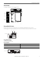
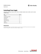
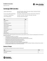
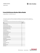
About the Module
Use this figure to identify the external features of the module.
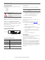
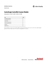
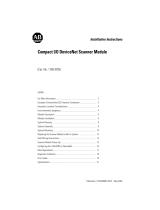
Determine Module Slot Location
Install the module in any slot in the ControlLogix chassis. You can install multiple 1756-DNB scanners in the same chassis.
The following figure shows chassis slot numbering in a 4-slot chassis. Slot 0 is the first slot and is always the leftmost slot in the chassis.
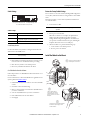
Change Module Settings
The module ships with these settings.
Factory Setting Values
Factory Settings Value
Rotary switches 999
Communication (data) rate Software settable (default 125 Kbps)
Node address Software settable (default 63)
31713-M
Front View
Side View
Top View
Backplane
Connector
USB Port
Front
Panel
DeviceNet
Port
Power Supply
Slot 0
Slot 1
Slot 2
Slot 3
Chassis
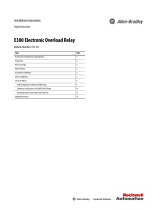
20806
DeviceNet Node Address Rotary
Switches
Front of Module
Top of Module
31587
Communication (Data)
Rate Rotary Switch

6 Rockwell Automation Publication 1756-IN065A-EN-P - September 2017
ControlLogix DeviceNet Scanner Module
Set the Communication Rate
The 1756-DNB scanner supports the following DeviceNet network
communication rates:
•125 Kbps
•250 Kbps
•500 Kbps
The factory default setting is 125 Kbps.
Change the communication rate by setting the rotary switch or
commissioning the 1756-DNB scanner in RSNetWorx™ for DeviceNet
software.
Use the switch to select a specific communication rate. When the
switch is set to 3...9 (except for 888), you can configure the
communication rate with RSNetWorx for DeviceNet software. When
all three switches are set to 8, the 1756-DNB scanner resets to factory
default settings at powerup.
See Restore the Factory Default Settings for more information.
See the following table for switch settings.
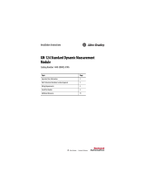
Communication Rate Rotary Switch
Set the Rotary Switch
Use the communication (data) rate rotary switch to change the
communication rate.
1. If the module is removed from the chassis, be sure that power is
removed or the area is nonhazardous before proceeding.
2. Move the rotary switch to the desired position.
3. If necessary, reinstall the module into the chassis.
Use RSNetWorx for DeviceNet Software
Follow this procedure to use RSNetWorx for DeviceNet software to set
the communication rate.
For more information, see the DeviceNet Modules in Logix5000™
Control Systems User Manual, publication DNET-UM004
.
1. In RSNetWorx for DeviceNet software, select the 1756-DNB
scanner.
2. Select Tools and Node Commissioning.
3. Browse to the DeviceNet network for the 1756-DNB scanner
you want to commission.
4. Select the 1756-DNB scanner you want to commission.
5. In the Data Rate field, select the communication (data) rate.
6. Click Apply.
7. Cycle power to the 1756-DNB scanner.
Set the Node Address
The 1756-DNB scanner supports DeviceNet node addresses 00...63.
The factory default setting is node address 63.
Change the node address by setting the rotary switches or
commissioning the 1756-DNB scanner in RSNetWorx for DeviceNet
software.
Use the switches to select any network address from 00 through 63.
When the switches are set outside of this range (except for 888), you
can configure the node address with RSNetWorx for DeviceNet
software. When all three switches are set to 8, the 1756-DNB scanner
resets to factory default settings at powerup. See Restore the Factory
Default Settings for more information. See the following table for
switch settings.
ATTENTION: Do not change the communication rate on an active
network. Unpredictable operation may result. In addition, the new
communication rate does not take effect until you cycle power to
the 1756-DNB scanner.
Switch Settings and Communication Rate
Switch Setting Communication Rate
0 125 Kbps
1 250 Kbps
2 500 Kbps
8
When all three switches are set to 8, this resets the 1756-DNB
scanner to factory default settings.
Do not use for normal operation.
All other values
Select the communication rate with RSNetWorx for DeviceNet
software.
Front of Module
Top of Module
Communication (Data) Rate Rotary Switch
IMPORTANT For ease of access, remove the module from the chassis before
proceeding.

Rockwell Automation Publication 1756-IN065A-EN-P - September 2017 7
ControlLogix DeviceNet Scanner Module
Switch Settings
Set the Rotary Switches
Use the node address rotary switches to change the DeviceNet node
address for the 1756-DNB scanner.
1. If the module is removed from the chassis, be sure that power is
removed or the area is nonhazardous before proceeding.
2. Move the rotary switches to the desired position.
3. If necessary, reinstall the module into the chassis.
Use RSNetWorx for DeviceNet Software
Follow this procedure to use RSNetWorx for DeviceNet software to set
the node address.
For more information, see DeviceNet Modules in Logix5000 Control
Systems, publication DNET-UM004
.
1. In RSNetWorx for DeviceNet software, select the 1756-DNB
scanner.
2. Click Tools > Node Commissioning.
3. Browse to the DeviceNet network for the 1756-DNB scanner
you want to commission.
4. Select the 1756-DNB scanner you want to commission.
5. In the Address field, select the node address.
6. Click Apply.
Restore the Factory Default Settings
The out-of-box reset clears the scanlist (including ADR configuration
recovery files) and return all software setting attributes to their default
values.
Follow this procedure to restore the factory default communication
rate and node address.
1. Set the switches to 888.
2. Restore power to the module.
When the out-of-box reset is complete, the alphanumeric
display repeatedly scrolls the message Reset Complete -
Change Switch Settings. During this time, the module does
not respond to communication from any port (including the
backplane, DeviceNet connector, or USB port).
3. After the module resets, perform the following steps.
a. Set the switches to the desired position.
b. Restore power to the module.
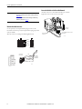
Install the Module in the Chassis
Switch Settings
Switch Setting Node Address
0...63 DeviceNet node address 00...63
88
When all three switches are set to 8, resets the 1756-DNB scanner to
factory default settings. Do not use for normal operation.
All other values Select the node address with RSNetWorx for DeviceNet software.
IMPORTANT
For ease of access, remove the module from the chassis
before proceeding.
DeviceNet Node Address Rotary Switches
Top of Module
Least Significant Digit Switch
Most Significant Digit Switch
Front of
Module
IMPORTANT Do not use the 888 switch setting during normal module
operation.
31715-M
Align the circuit board with top
bottom guides in the chassis.
1
Slide the module into the
chassis. Make sure that the
module backplane connector
properly connects to the chassis
backplane.
2
The module is properly installed when it is
flush with the power supply or other
installed modules.
3
Circuit Board

8 Rockwell Automation Publication 1756-IN065A-EN-P - September 2017
ControlLogix DeviceNet Scanner Module
Wire the DeviceNet Connector
Use an open-style 5- or 10-position linear plug to connect to the
DeviceNet network. An open-style 10-position linear plug is provided
with your module.
Wire the connector according to the following illustrations.
Connect the Module to the DeviceNet Network
Attach the connector to the module DeviceNet port as shown.
Tighten the screws on the connector as needed.
IMPORTANT For detailed DeviceNet connection information, see the
DeviceNet Media Design and Installation Guide, publication
DNET-UM072.
Also see the Industrial Automation Wiring and Grounding
Guidelines, publication 1770-2.1.
Color Chips (dots)
Red Dot
Black Dot
Blue Dot
White Dot
10-position Plug
5-position Plug
20474-
D
D
D
D
D
Linear Plug
10-position
Drop Line or
DeviceNet
Trunk Cable
Red
White
Bare
Blue
Black
31716-M
10-position
Linear Plug
DeviceNet Port
Connector
DeviceNet Drop Line or Trunk
Connector

Rockwell Automation Publication 1756-IN065A-EN-P - September 2017 9
ControlLogix DeviceNet Scanner Module
Specifications
Attribute 1756-DNB, 1756-DNBK
Temperature, operating
IEC 60068-2-1 (Test Ad, Operating Cold),
IEC 60068-2-2 (Test Bd, Operating Dry Heat),
IEC 60068-2-14 (Test Nb, Operating Thermal Shock)
0 °C < Ta < +60 °C (+32 °F < Ta < +140 °F)
Temperature, surrounding air, max. 60 °C (140 °F)
Voltage and current ratings
Backplane: 5.1V DC, 400 mA
DeviceNet Power: 60 mA @ 11...2V DC CL 2/SELV limited to 100VA
Isolation voltage
50V (continuous),Basic Insulation Type, DeviceNet to Backplane
No isolation between USB and Backplane
Type tested at 860V AC for 60 s
Terminal block torque specs DeviceNet connector: 0.56…0.79 N•m (5…7 lb•in)
Enclosure type rating None (open-style)
North American temp code T4A
ATEX Temp Code T4

Allen-Bradley, Rockwell Automation, ControlLogix, and Rockwell Software are trademarks of Rockwell Automation, Inc.
Trademarks not belonging to Rockwell Automation are property of their respective companies.
Rockwell Otomasyon Ticaret A.Ş., Kar Plaza İş Merkezi E Blok Kat:6 34752 İçerenköy, İstanbul, Tel: +90 (216) 5698400
Rockwell Automation maintains current product environmental information on its website at
http://www.rockwellautomation.com/rockwellautomation/about-us/sustainability-ethics/product-environmental-compliance.page
.
Publication 1756-IN065A-EN-P - September 2017 PN-460559
Supersedes Publication 1756-IN566D-EN-P - June 2008 Copyright © 2017 Rockwell Automation, Inc. All rights reserved. Printed in the U.S.A.
Additional Resources
These documents contain additional information concerning related products from Rockwell Automation.
You can view or download publications at http://www.rockwellautomation.com/global/literature-library/overview.page. To order paper copies of
technical documentation, contact your local Allen-Bradley distributor or Rockwell Automation sales representative.
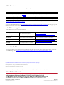
Rockwell Automation Support
Use the following resources to access support information.
Documentation Feedback
Your comments will help us serve your documentation needs better. If you have any suggestions on how to improve this document, complete the
How Are We Doing? form at http://literature.rockwellautomation.com/idc/groups/literature/documents/du/ra-du002_-en-e.pdf
.
Technical Support Center
Knowledgebase Articles, How-to Videos, FAQs, Chat, User
Forums, and Product Notification Updates.
https://rockwellautomation.custhelp.com/
Local Technical Support Phone Numbers Locate the phone number for your country. http://www.rockwellautomation.com/global/support/get-support-now.page
Direct Dial Codes
Find the Direct Dial Code for your product. Use the code to
route your call directly to a technical support engineer.
http://www.rockwellautomation.com/global/support/direct-dial.page
Literature Library
Installation Instructions, Manuals, Brochures, and
Technical Data.
http://www.rockwellautomation.com/global/literature-library/overview.page
Product Compatibility and Download
Center (PCDC)
Get help determining how products interact, check
features and capabilities, and find associated firmware.
http://www.rockwellautomation.com/global/support/pcdc.page
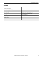
Resource Description
DeviceNet Media Design and Installation Guide, publication DNET-UM072 Planning and installing a DeviceNet network
DeviceNet Modules in Logix5000 Control Systems, publication DNET-UM004 Programming, configuring, using, and troubleshooting DeviceNet modules
Industrial Automation Wiring and Grounding Guidelines, publication 1770-4.1 Grounding and wiring Allen-Bradley programmable controllers
National Electrical Code - Published by the National Fire Protection Association of Boston, MA. Wire sizes and types for grounding electrical equipment
Industrial Automation Wiring and Grounding Guidelines, publication 1770-4.1
Provides general guidelines for installing a Rockwell Automation industrial system.
Product Certifications website,
http://www.rockwellautomation.com/global/certification/overview.page
Provides declarations of conformity, certificates, and other certification details.
-
 1
1
-
 2
2
-
 3
3
-
 4
4
-
 5
5
-
 6
6
-
 7
7
-
 8
8
-
 9
9
-
 10
10


Allen-Bradley ControlLogix DeviceNet Installation Instructions Manual
- Taper
- Installation Instructions Manual
dans d''autres langues
- English: Allen-Bradley ControlLogix DeviceNet
Documents connexes
-
 Allen-Bradley 1756-EN3TRK Guide d'installation
-
 Allen-Bradley ControlLogix 1756-EN2F Installation Instructions Manual
-
Allen-Bradley 1756-PA75RK Installation Instructions Manual
-
 Allen-Bradley ControlLogix DeviceNet 1756-DNB Installation Instructions Manual
-
 Allen-Bradley ControlNet-to-DeviceNet 1788-CN2DN Installation Instructions Manual
-
Allen-Bradley 1756-OV16E Installation Instructions Manual
-
 Allen-Bradley 1756-PB72 Installation Instructions Manual
-
 Allen-Bradley ControlLogix ControlNet Scanner Module Installation Instructions Manual
-
 Allen-Bradley E300 Installation Instructions Manual
-
 Allen-Bradley ControlNet PLC-5 Guide de démarrage rapide


Autres documents
-
 Allen Bradley Allen-Bradley ControlLogix 5580 Controllers Modern Control System Manuel utilisateur
-
 Allen Bradley Allen-Bradley 5580 ControlLogix Controllers Mode d'emploi
-
Spectrum Controls 1756-RMS-SC Quick Start
-
-
 Rockwell Automation 40072-107-01 Installation Instructions Manual
-
 Rockwell Automation Allen-Bradley XM-124 Installation Instructions Manual
-
 Rockwell Automation Allen-Bradley FactoryTalk Historian ME Installation Instructions Manual
-
Puls QS10.DNET Manuel utilisateur
-
Eks RAS Quick Start


