Allen-Bradley ControlLogix DeviceNet 1756-DNB Installation Instructions Manual
- Taper
- Installation Instructions Manual

Packing Data
PK
Publication 1756-5.66 – May 1998
(Catalog Number 1756-DNB)
To the Installer
The
1756-DNB module is a DeviceNet
t
scanner module that resides in a
ControlLogixt chassis and provides DeviceNet monitoring, configuration,
and I/O scan capabilities.
Use this document as a guide to install the ControlLogix DeviceNet
scanner module.
To See page
Handle the module 2
Understand Compliance to European Union Directives 3
Understand the module software features 4
Identify the module hardware features 6
Prepare to install the module 7
Prepare the chassis for installation 8
Install the module into the chassis 8
Wire the DeviceNet connector 12
Connect the module to the DeviceNet network 13
Apply chassis power 14
Check module alphanumeric indicators 14
Use the manual configuration pushbutton 15
Interpret the node address/status indicator 16
Interpret the status indicators 18
Installation Instruction
s
AB Parts

ControlLogix DeviceNet Scanner Module Installation Instructions2
Publication 1756-5.66 – May 1998
To See page
Understand the ControlLogix controller interface 22
Understand CSA Hazardous Location Approval 25
Understand module specifications 27
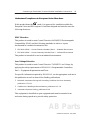
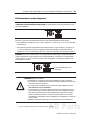
Handling the Module
ATTENTION:
The module uses CMOS technology
, which is highly
sensitive to electrostatic dischar
ge (ESD). ESD may be present
whenever you are handling the module. Handling a module without
any ESD protection can cause internal circuit damage that may not be
apparent during installation or initial use.
T
ake these precautions to guard against ESD damage:
• Before handling the module, be sure to wear the provided static strap and
touch a grounded object to discharge any built-up static charge.
• Avoid touching the backplane connector or interface connector pins located
on the module.
• If the module is not in use, store it in the anti-static clamshell in which the
module was shipped.
Important: Remember
, a computer with ac power disconnected is
not
a
grounded object.

ControlLogix DeviceNet Scanner Module Installation Instructions
3
Publication
1756-5.66 – May 1998
Understand Compliance to European Union Directives
If this product bears the mark, it is approved for installation within the
European Union and EEA regions. It has been designed and tested to meet the
following directives.
EMC Directive
This product is tested to meet Council Directive 89/336/EEC Electromagnetic
Compatibility (EMC) and the following standards, in whole or in part,
documented in a technical construction file:
• EN 50081-2EMC – Generic Emission Standard, Part 2 – Industrial Environment
• EN 50082-2EMC – Generic Immunity Standard, Part 2 – Industrial Environment
This product is intended for use in an industrial environment.
Low Voltage Directive
This product is tested to meet Council Directive 73/23/EEC Low Voltage, by
applying the safety requirements of EN 61131–2 Programmable Controllers,
Part 2 – Equipment Requirements and Tests.
For specific information required by EN 61
131-2, see the appropriate sections in
this publication as well as these Allen-Bradley publications:
• Industrial Automation Wiring and Grounding Guidelines for Noise Immunity,
publication 1770-4.1
• Guidelines for Handling Lithium Batteries, publication AG-5.4
• Automation Systems Catalog, publication B111
This
equipment is classified as open equipment and must be mounted in an
enclosure during operation to provide safety protection.
AB Parts

ControlLogix DeviceNet Scanner Module Installation Instructions4
Publication 1756-5.66 – May 1998
Understand the Module’s Software Features
The 1756-DNB module has the following software features. Y
ou activate these
features by using DeviceNetManager
t software (catalog no. 1787-MGR) or
RSNetWorx for DeviceNett. For more information, refer to the DeviceNet
Manager Software User Manual, publication 1787-6.5.3, the appropriate
RSNetWorx for DeviceNet documentation, and the 1756-DNB Scanner
Configuration Manual, publication 1756-6.5.15.
Slave Mode
The
slave mode feature allows processor
-to-processor communication. Slave
mode also allows the scanner to perform as a slave device to another master on
the network.
Like any other slave, when the scanner module is in slave mode, it exchanges
data with only one master. You control what information is exchanged through
scan list configuration and associated mapping functions of DeviceNet Manager
software.
The slave mode function has these variations:
Scanner is in this mode when it
Null contains an empty or disabled scan list (out-of-box default)
Master serves as a master to one or more slaves but is not
simultaneously serving as a slave to another master
Slave serves as a slave to another master
Dual serves as both a master to one or more slaves and as a
slave to another master simultaneously

ControlLogix DeviceNet Scanner Module Installation Instructions
5
Publication
1756-5.66 – May 1998
Change of State
The
scanner module can send and receive data on a change of state basis with
slave devices that also have this feature. Data is sent:
•
whenever a data change occurs, or
•
at a user
-configurable heartbeat rate
Change of state increases system performance by reducing network traf
fic, since
data is only sent on an as-needed basis. Use DeviceNet Manager software to
activate this feature.
Cyclic I/O
The
scanner module can send and receive data on a cyclic basis with slave
devices that also have this feature.
Cyclic I/O increases system performance by reducing network traf
fic, since data
is only sent at a user
-configurable rate. Use DeviceNet Manager or RSNetWorx
for DeviceNet software to activate this feature.
AB Parts

ControlLogix DeviceNet Scanner Module Installation Instructions6
Publication 1756-5.66 – May 1998
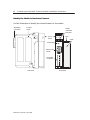
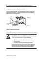
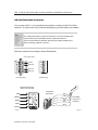
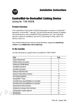
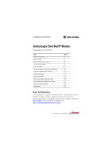
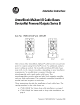
Identify the Module’s Hardware Features
Use this illustration to identify the external features of the module.
MOD/NET
DeviceNetTM
OK
Front ViewSide View
Backplane
Connector
Door
Front
Panel
DeviceNet
Connector
Health
and status
Indicators
Product
Label
Wiring Color
Codes
I/O
MOD/NET
Pushbutton
Label

ControlLogix DeviceNet Scanner Module Installation Instructions
7
Publication
1756-5.66 – May 1998
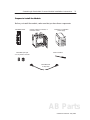
Prepare to Install the Module
Before
you install the module, make sure that you have these components.
1756-DNB
module
1756-P
A72 or 1756-PB72
power supply
1756-A4, 1756-A7, 1756-A10, or
1756-A13 chassis
small screwdriver
DeviceNet open-style
5- or 10-position connector
DeviceNet trunk
or drop cable
AB Parts

ControlLogix DeviceNet Scanner Module Installation Instructions8
Publication 1756-5.66 – May 1998
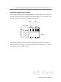
Prepare the Chassis for Module Installation
Before you install the module, you must install and connect a ControlLogix
chassis and power supply
. To install these products, refer to the installation
instructions you received with them.
20805-M
Power
supply
Chassis
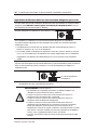
Install or Remove the Module
This
module is designed to be installed or removed while chassis power is applied.
!
ATTENTION: When you insert or remove a module while
backplane power is on, an electrical arc may occur. An electrical
arc can cause personal injury or property damage by:
•
sending an erroneous signal to your system’
s field
device causing unintended machine motion or loss of
process control
•
causing an explosion in a hazardous environment
Repeated electrical arcing causes excessive wear to contacts on
both the module and its mating connector
. W
orn contacts may
create electrical resistance that can af
fect module operation.

ControlLogix DeviceNet Scanner Module Installation Instructions
9
Publication
1756-5.66 – May 1998
Determine Module Slot Location
This
example shows chassis slot numbering in a 4-slot chassis. Slot 0 is the first
slot and is always located to the right of the power supply. Y
ou can use any size
ControlLogix chassis and install the module in any slot.
Slot 0 Slot 2
Slot 1 Slot 3
Power Supply
Chassis
You
can use multiple 1756-DNB modules in the same chassis. Y
ou can use as
many 1756-DNB modules as your power supply can accommodate (i.e., number
for which the power supply is rated).
AB Parts

ControlLogix DeviceNet Scanner Module Installation Instructions10
Publication 1756-5.66 – May 1998
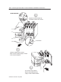
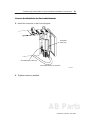
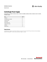
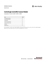
Install the Module
Align the circuit board with top
and bottom guides in the chassis.
Slide the module into the chassis.
Make sure the module properly connects
to the chassis backplane.
The module is fully installed
when it is flush with the power
supply or other installed modules.
1
2
3
Circuit board

ControlLogix DeviceNet Scanner Module Installation Instructions
11
Publication
1756-5.66 – May 1998
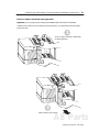
Remove or Replace the Module (when applicable)
Push on upper and lower module tabs
to disengage them.
1
Slide module out of chassis.
2
Important: If you are replacing an existing 1756-DNB module with another 1756-DNB
module and you want to resume identical system operation, you must install the new module
in the same slot.
AB Parts

ControlLogix DeviceNet Scanner Module Installation Instructions12
Publication 1756-5.66 – May 1998
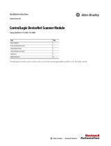
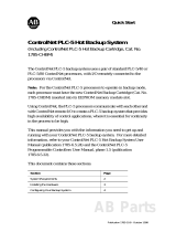
Wire the DeviceNet Connector
Use an open-style 5- or 10-position linear plug to connect to the DeviceNet
network. An open-style 10-position linear plug is provided with your module.
For detailed DeviceNet connection information, see the DeviceNet Cable
System Planning and Installation Manual, publication DN-6.7.2.
Also see the Industrial Automation Wiring and Grounding Guidelines for
Noise Immunity, publication 1770-4.1.
Wire the connector according to these illustrations.
Color
chips (dots)
red dot
white dot
blue dot
black dot
10-position plug
5-position plug
20474-M
10-position
linear plug
DeviceNet
drop line or
trunk line
D
D
D
D
D
Black
Blue
White
Red
Bare
RED
WHITE
BARE
BLUE
BLACK
Module label shows
wiring color scheme:
20479-M

ControlLogix DeviceNet Scanner Module Installation Instructions
13
Publication
1756-5.66 – May 1998
Connect the Module to the DeviceNet Network
1. Attach the connector to the DeviceNet port.
20441–M
DeviceNet drop line or trunk line
10-position
linear plug
DeviceNet port connector
2. Tighten screws as needed.
AB Parts

ControlLogix DeviceNet Scanner Module Installation Instructions14
Publication 1756-5.66 – May 1998
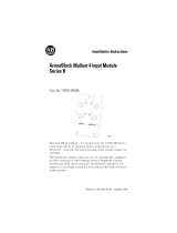
Apply Chassis Power
ON
POWER
OFF
Po
wer
s
u
pp
ly in
d
icato
r
i
s
green when power supply is
working correctly.
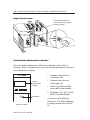
Check Module Alphanumeric Indicators
Check the module alphanumeric indicators to determine if the module is
operating. When you apply chassis power
, the module alphanumeric indicators
cycle through these displays:
• Firmware major revision
(01 through 128)
• Firmware minor revision
(01 through 255)
• MAC ID (A#00 to A#63,
with A#63 as the default)
• Baud rate (125, 250, or 500,
with 125 as the default)
Use
the DeviceNet Manager
software or 1756-DNB pushbutton
to change the baud rate and MAC
ID.
Top part of module
DeviceNetTM
Module
alphanumeric
indicator
MOD/NET I/O OK
Pushbutton

ControlLogix DeviceNet Scanner Module Installation Instructions
15
Publication
1756-5.66 – May 1998
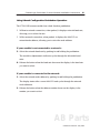
Using Manual Configuration Pushbutton Operation
The 1756-DNB scanner module has a dual-function pushbutton.
• Without a network connection, when pushed, it displays network baud rate,
allowing you to select the rate.
• W
ith a network connection, when pushed, it displays the MAC ID or
network node address, allowing you to select the node address.
If your module is not connected to a network:
3.
Select the network baud rate by pushing in and holding the pushbutton.
The module’s alphanumeric indicator cycles through the allowable baud
rates.
4.
Release the button when the baud rate shown on the display is the baud rate
you want to select.
If your module is connected to the network:
1.
Select the network node address by pushing in and holding the pushbutton.
The display starts at the
current MAC ID and cycles through the network
node addresses.
2.
Release the button when the address number shown on the display is the
number you want to select.
AB Parts

ControlLogix DeviceNet Scanner Module Installation Instructions16
Publication 1756-5.66 – May 1998
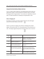
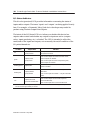
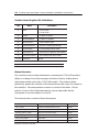
Interpret the Node Address/Status Indicator
Your
1756-DNB scanner module has a node address/status indicator that uses
alphanumeric displays to indicate diagnostic information about your module.
The display flashes at approximately 1 second intervals, depending on network
traffic. The table summarizes the meanings of the alphanumeric codes.
What Is Displayed?
The
display
, for instance, for RUN would look like this, and would toggle
between the network address and the mode:
If there is a problem
, the display looks like this, and displays the network
address, followed by the MAC ID of the problem node, followed by the error
code. The display toggles through these elements until the error is corrected.
Alphanumeric
Code
Description Action
70 Scanner
failed Duplicate Node Address
check
Change the scanner address to another
available one. The node address you selected
is already in use on that network.
71
Illegal data in scan list table (node
number alternately flashes).
Reconfigure the scan list table and remove any
illegal data.
72
Slave device stopped communicating
(node number alternately flashes).
Inspect the field devices and verify
connections.
73 Device’
s identity information does not
match electronic key in scan list table
entry (node number alternately flashes).
V
erify that the correct device is at this node
number
. Make sure that the device at the
flashing node address matches the desired
electronic key (vendor
, product code, product
type).
74
Data overrun on port detected.
Modify your configuration and check for invalid
data. Check network communication traf
fic.
A#01
RUN
A#01
N#33
E#72

ControlLogix DeviceNet Scanner Module Installation Instructions
17
Publication
1756-5.66 – May 1998
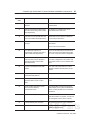
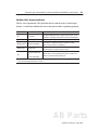
Alphanumeric
Code
ActionDescription
76
No direct network traf
fic for scanner
detected.
None. The scanner hears other network
communication.
77
Data size expected by the device does
not match scan list entry (node number
alternately flashes).
Reconfigure your module for the correct
transmit and receive data sizes.
78 Slave device in scan list table does not
exist (node number alternately flashes).
Add the device to the network, or delete the
scan list entry for that device.
79
Scanner has failed to transmit a
message.
Make sure that your module is connected to a
valid network.
Check for disconnected cables.
82
Error detected in sequence of
fragmented I/O messages from device
(node number alternately flashes).
Check scan list table entry for slave device to
make sure that input and output data lengths
are correct. Check slave device configuration.
83
Slave device is returning error
responses when scanner attempts to
communicate with it (node number
alternately flashes).
Check accuracy of scan list table entry
. Check
slave device configuration. Slave device may
be in another master
’s scan list. Reboot slave
device.
84 Scanner is initializing the DeviceNet
network.
None. This code clears itself once scanner
attempts to initialize all slave devices on the
network.
85
Data size larger than 255 bytes (node
number alternately flashes).
Configure the device for a smaller data size.
86
Device is producing zero length data
(idle state) while scanner is in Run
Mode.
Check device configuration and slave node
status.
91 Bus-of
f condition detected on comm
port. Scanner is detecting
communication errors.
Check DeviceNet connections and physical
media integrity
. Check system for failed slave
devices or other possible sources of network
interference.
95
Application FLASH update in progress.
None. Do not disconnect the module while
application FLASH is in progress. Y
ou will lose
any existing data in the scanner
’
s memory
.
97
Scanner halted by user command.
Check ladder program for cause of fault bits.
IDLE
Scanner is in IDLE mode.
Put controller in RUN mode. Enable RUN bit in
module command register
.
AB Parts

ControlLogix DeviceNet Scanner Module Installation Instructions18
Publication 1756-5.66 – May 1998
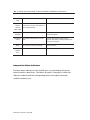
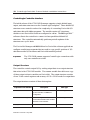
Alphanumeric
Code
ActionDescription
Network
Address
Displays
A#00
- A#63
Normal operation. The numeric display
matches the scanner
’
s node address on
the DeviceNet network.
Do nothing.
Network
Disabled
User has disabled communication port
Reconfigure your module. Check Module
Command Register
.
No Network
Power
No network power detected on comm
port.
Provide network power
. Make sure that
scanner drop cable is providing network power
to scanner comm port.
NoRX No scan list is active in the module.
Enter a scan list.
Severe
Network
Error
Scanner is in FAUL
T mode.
Check ladder program for cause of fault bits.
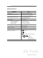
Interpret the Status Indicators
The three status indicators on the module give you information about your
network and its connections. The tables on pages 19 through 21 outline the
indicator condition and the corresponding status, and explain what each
condition means to you.

ControlLogix DeviceNet Scanner Module Installation Instructions
19
Publication
1756-5.66 – May 1998
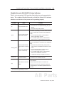
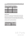
Module/Network (MOD/NET) Status Indicator
This bi-color (green/red) LED provides limited device and communication
status. The combined Module/Network (or Mod/Net) Status LED indicates
whether or not the device has power and is operating properly.
Condition Status Indicates
off not
powered/not online
Device is not online.
•
The device has not completed the Dup_MAC_ID
test yet.
•
The device may not be powered.
green
device operational AND
online and connected
The device is operating in a normal condition and the
device is online with connections in the established
state.
•
For a Group 2 Only device, it means that the
device is allocated to a Master
.
•
For a UCMM capable device, it means that the
device has one or more established connections.
flashing green
1
device operational AND
online and not connected,
or
device online AND device
needs commissioning
The device is operating in a normal condition and the
device is online with no connections in the established
state.
• The
device has passed the Dup_MAC_ID test, is
online, but has no established connections to other
nodes.
•
For a Group 2 Only device, it means that this
device is not allocated to a master
.
•
For a UCMM capable device, it means that the
device has no established connections.
•
Configuration missing, incomplete, or incorrect.
flashing red
1
minor fault and/or
connection time-out
Recoverable fault and/or one or more I/O
connections are in the timed-out state.
red
critical fault or critical link
failure
The device has an unrecoverable fault and may need
to be replaced.
Failed communication device. The device has
detected an error that has rendered it incapable of
communicating on the network (duplicate MAC ID or
bus-off).
1
The
flash rate of the LED is approximately 1 flash per second. The LED should be on for approximately 0.5
seconds and of
f for approximately 0.5 seconds.
AB Parts

ControlLogix DeviceNet Scanner Module Installation Instructions20
Publication 1756-5.66 – May 1998
I/O Status Indicator
This bi-color (green/red) LED provides information concerning the status of
inputs and/or outputs. The terms ‘inputs’ and ‘outputs’ are being applied loosely
here. For example, a Pneumatic V
alve Pack device developer may model its
product using Discrete Output Point Objects.
The intent of the I/O Status LED is to inform you whether this device has
outputs under control and whether any outputs or inputs are active (outputs
active, inputs producing, etc.) or faulted. The LED is intended to reflect the
mode/state of the inputs and outputs, not necessarily the on/of
f condition of the
I/O points themselves.
Condition Output
Status
Indicates
off
output(s) inactive
input(s) inactive
All output are inactive.
All inputs are inactive.
green
output(s) active
input(s) active
One or more outputs are active and under control,
and no outputs are ‘faulted’.
One or more inputs are active and producing data,
and no inputs are ‘faulted’.
flashing green
1
output(s) idle
One or more outputs are idle, and no outputs are
active or ‘faulted’.
flashing red
1
output(s) faulted
input(s) faulted
One or more outputs are ‘faulted’ — may be in the
fault state.
One or more inputs are ‘faulted’ — may be in the fault
state.
red
output(s) forced of
f
input unrecoverable fault
One or more outputs are forced of
f (may be an
unrecoverable fault).
One or more inputs has an unrecoverable fault.
1
The
flash rate of the LED is approximately 1 flash per second. The LED should be on for approximately 0.5
seconds and of
f for approximately 0.5 seconds.
La page est en cours de chargement...
La page est en cours de chargement...
La page est en cours de chargement...
La page est en cours de chargement...
La page est en cours de chargement...
La page est en cours de chargement...
La page est en cours de chargement...
La page est en cours de chargement...
-
 1
1
-
 2
2
-
 3
3
-
 4
4
-
 5
5
-
 6
6
-
 7
7
-
 8
8
-
 9
9
-
 10
10
-
 11
11
-
 12
12
-
 13
13
-
 14
14
-
 15
15
-
 16
16
-
 17
17
-
 18
18
-
 19
19
-
 20
20
-
 21
21
-
 22
22
-
 23
23
-
 24
24
-
 25
25
-
 26
26
-
 27
27
-
 28
28


Allen-Bradley ControlLogix DeviceNet 1756-DNB Installation Instructions Manual
- Taper
- Installation Instructions Manual
dans d''autres langues
Documents connexes
-
 Allen-Bradley ControlNet-to-DeviceNet 1788-CN2DN Installation Instructions Manual
-
 Allen-Bradley ControlLogix DeviceNet Installation Instructions Manual
-
 Allen-Bradley 1756-PB72 Installation Instructions Manual
-
 Allen-Bradley ControlLogix 1756-EN2F Installation Instructions Manual
-
 Allen-Bradley ControlLogix ControlNet Scanner Module Installation Instructions Manual
-
 Allen-Bradley ControlNet PLC-5 Guide de démarrage rapide
-
 Allen-Bradley ArmorBlock MaXum 4 Installation Instructions Manual
-
 Allen-Bradley ArmorBlock MaXum 1792D-CB12JP Installation Instructions Manual