
INSTALLATION GUIDE
E120
For models QI0120 & QI0122


ENGLISH EN
DEUTSCH DE
ESPAÑOL ES
FRANÇAIS FR
ITALIANO IT
POLSKIE PL
AR

1
Important safety information and warnings ........................................................................................ 2
Introduction ......................................................................................................................................... 4
Package contents ............................................................................................................................... 4
E120 System Schematic ..................................................................................................................... 6
Planning E120 positioning and back box locations ............................................................................ 7
First x basic wiring ............................................................................................................................. 8
First x for line output .......................................................................................................................... 9
Bathroom installation guide ................................................................................................................ 9
Wiring for two pairs of speakers ....................................................................................................... 11
Second x .......................................................................................................................................... 12
Removing the E120 wall panel .......................................................................................................... 14
Specication ...................................................................................................................................... 15
Warranty ............................................................................................................................................ 16
Contents

2
ENGLISH EN
Important safety information and warnings
1 Notices
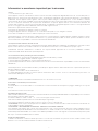
1.1 FCC Statement (for US Customers)
This equipment has been tested and found to comply with the limits for a Class B digital device, pursuant to Part 15 of the FCC
Rules. These limits are designed to provide reasonable protection against harmful interference in a residential installation. This
equipment generates uses and can radiate radio frequency energy and, if not installed and used in accordance with the instructions,
may cause harmful interference to radio communications. However, there is no guarantee that interference will not occur in a
particular installation. If this equipment does cause harmful interference to radio or television reception, which can be determined by
turning the equipment off and on, the user is encouraged to try to correct the interference by one or more of the following measures:
• Reorient or relocate the receiving antenna.
• Increase the separation between the equipment and receiver.
• Connect the equipment into an outlet on a circuit different from that to which the receiver is connected.
• Consult the dealer or an experienced radio/TV technician for help.
This device complies with part 15 of the FCC Rules. Operation is subject to the following two conditions:(1) This device may
not cause harmful interference, and (2) this device must accept any interference received, including interference that may cause
undesired operation.
1.2 FCC Radiation Exposure
This equipment complies with FCC radiation exposure limits set forth for an uncontrolled environment. This equipment should be
installed and operated with minimum distance 20cm between the radiator & your body.
CAUTION! Any Changes or modifications not expressly approved by Q Acoustics could void the user’s authority to operate the
equipment.
1.3 Industry Canada Statement (for Canadian Customers)
This device complies with Industry Canada licence-exempt RSS standard(s).
Operation is subject to the following two conditions:
(1) This device may not cause interference, and
(2) This device must accept any interference, including interference that may cause undesired operation of the device.
Le présent appareil est conforme aux CNR d’Industrie Canada applicables aux appareils radio exempts de licence. L’exploitation
est autorisée aux deux conditions suivantes:
(1) l’appareil ne doit pas produire de brouillage, et
(2) l’utilisateur de l’appareil doit accepter tout brouillage radioélectrique subi, même si le brouillage est susceptible d’en compromettre
le fonctionnement.
1.4 Bluetooth
This unit contains a Class 2
Bluetooth
transmitter working at 2.4GHz.
2 Safety Information and Warnings
2.1 Moisture
• To reduce the risk of fire or electric shock, this apparatus should not be exposed to rain, moisture, dripping or splashing.
• Do not use this apparatus near water.
2.2 Remote Control Batteries
The remote control supplied with this unit contains a battery. To prevent battery leakage which may result in bodily injury, property
damage, or damage to the unit:
• Install the battery correctly, + and - as marked on the unit.
• Remove the battery when the unit is not used for a long time.
• Do not expose the battery or remote control to excessive heat, including sunshine.
• CAUTION: Danger of explosion if battery is incorrectly replaced. Replace only with the same or equivalent type.
• WARNING - DO NOT INGEST BATTERY - CHEMICAL BURN HAZARD.
• If the battery is swallowed, it can cause severe internal burns in just 2 hours and can lead to death. Keep new and used batteries
away from children. If the battery compartment does not close securely, stop using the product and keep it away from children. If you
think batteries might have been swallowed or placed inside any part of the body, seek immediate medical attention
Disposal of Batteries
The battery supplied contains perchlorate material and in many areas batteries may not be disposed of with your household waste.
Please ensure you dispose of batteries according to local regulations.
The battery supplied does not contain the heavy metals mercury or cadmium.

3
2.5 Servicing
Servicing is required when the unit or mains cord has been damaged in any way, liquid has been spilled or objects have fallen into
the apparatus, the apparatus has been exposed to rain or moisture, it does not operate normally, or has been dropped.
Refer all servicing to qualified service personnel.
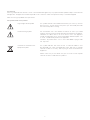
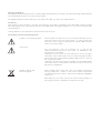
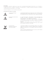
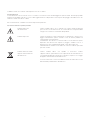
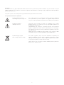
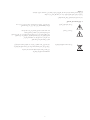
3.0 Symbols used on this product
High Voltage Hazard Symbol
Hazard Warning Symbol
Waste Electrical and Electronic
Equipment Symbol
This symbol indicates uninsulated material within your unit may cause an
electrical shock. For the safety of everyone in your household, please do
not remove the product covering.
The ‘exclamation mark’ calls attention to features for which you should
read this manual closely to prevent operation and maintenance problems.
WARNING: To reduce the risk of fire or electric shock, this apparatus
should not exposed to rain or moisture and object filled with liquids, such
as vases, should not be placed on this apparatus.
CAUTION: To prevent electric shock, match wide blade of plug to wide
slot, fully insert.
This symbol indicates that when the unit is to be discarded, it must
be separated from other household-type waste and sent to separate
collection facilities for recovery and recycling of electrical and electronic
equipment.
Please make sure you are familiar with your local rules on the separate
collection of electrical and electronic products.

4
ENGLISH EN
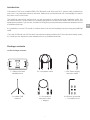
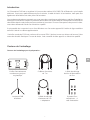
Q Acoustics E120 is an installed DAB, FM, Bluetooth and AUX input Hi-Fi system easily installed into
your room. It is particularly suited to kitchens, bathrooms* and bedrooms but could equally be used in
any other room in the house.
The following instructions assume that you are competent in general electrical installation skills. You
will need to mount a touch panel into a double gang back box and route cables from this box to the
speakers and mains. If you are not condent in doing this you should seek professional assistance from
a qualied electrician.
It is possible to connect TV sound or another device into the rear auxiliary line input using an additional
cable.
*The main E120 wall unit is IP54 rated. It should be located outside zone 2 of the electrical safety zones,
if in doubt you are advised to seek assistance from a qualied electrician.
Introduction
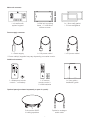
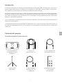
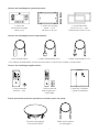
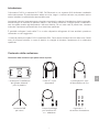
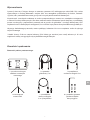
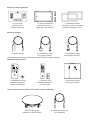
Package contents
1 x Indoor DAB
antenna
1 x Plastic stud wall
installation box
1 x 5m Power supply
extension cable
2 x 7m speaker cable
1st Fix Package contents:
1 x 3m antenna
extension cable
+ adaptor
6 x Rubber grommets
+ 1 x extraction tool

5
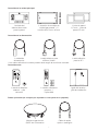
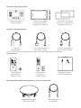
Main unit contents:
Power supply contents:
Additional contents:
1 x UK power cable*1 x Power supply
1 x In-wall audio
system keypad
1 x EU power cable*
1 x Waterproof remote
control + cell battery
Q Acoustics QI65C
in-ceiling speakers
Optical or analogue
audio cable
Optional parts (purchased separately or part of a pack):
1 x User guide +
installation guide
E120
INSTALLATION GUIDE
E120
USER GUIDE
1 x Premium
remote control +
2 x AAA batteries
1 x 1.0mm wall gasket
+ 2.5mm wall gasket
1 x Wall unit mounting
frame + 2 x M3.5mm
x40mm screws
* Power cable(s) supplied may vary depending on market version.

6
ENGLISH EN
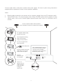
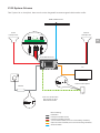
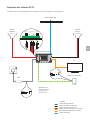
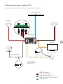
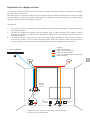
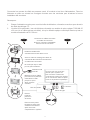
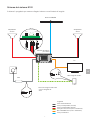
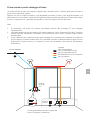
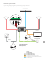
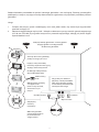
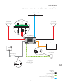
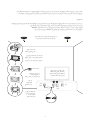
The system is designed to be connected together as shown below:
E120 System Schematic
DAB / FM antenna
Left speaker DC IN ANTENNASPEAKERS Right speaker
TV*
Other audio source*
PSU
E120 wall panel
*Only one source
*can connect to
*AUX at a time
Key:
Power cable
Speaker cable (left)
Speaker cable (right)
3.5mm jack cable (not supplied)
Optical mini TOSLINK (not supplied)
Antenna cable
+ R - - L +

7
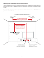
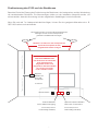
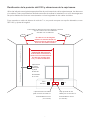
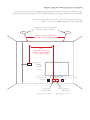
Use the guidelines below to plan the positioning of the back boxes, speakers, and cabling. Dimensions
should be checked prior to installation to ensure the layout works correctly with the supplied lengths
of cable.
If more than 7m of speaker cable is required then a suitable alternative such as QED 16/2 can be
purchased and cut to length.
Planning E120 positioning and back box locations
Typically 1m Typically 1.3m
Cut-outs for left and right ceiling speakers
Follow installation instructions supplied with speakers
7m maximum cable run from
speakers to E120 touch panel
using supplied cables
IMPORTANT DIMENSION
E120 must be located within
reach of a mains socket. The
supplied DC cable is 5m long
and should not be altered.
Mains
socket TV
Double gang
back box for
E120 touch
panel
47mm deep
Single gang back box
for DC cable breakout
44mm deep (not supplied)
Optional single gang back
box next to TV point
44mm deep (not supplied)

8
ENGLISH EN
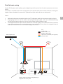
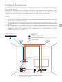
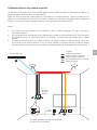
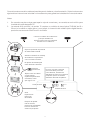
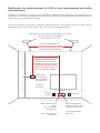
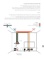
A basic E120 system with auxiliary optical digital input will have the rst x cable requirement as shown
below.
Cut holes for required back boxes and speakers. Run speaker and power cables as shown, leaving the
length of tails accessible for second x. Optional line input cable can be run at this point.
First fix basic wiring
Notes:
1. Switched mains socket required next to the DC extension cable for the power supply to plug in.
2. Single gang back box can be used for the optical AUX input cable. The can be terminated using
an optical termination plate such as the Nexxia Digital Optical Module Insert.
3. The supplied antenna cable can be attached to a normal quality coax cable which then connects
to an external antenna. If an external antenna can not be tted then place the supplied internal
antenna as recommended in the Antenna alignment section.
1
3
2
DAB / FM antenna
Tails approx.
100mm
Speker cables terminated using IMO plugs
Supplied with touch panel
Mains
socket TV
Key:
Power cable
Speaker cable (left)
Speaker cable (right)
Optical mini TOSLINK (not supplied)
Antenna cable

9
The analogue 3.5mm stereo line output can be used to connect an external amplier or sub-woofer.
Note that analogue audio signals are prone to picking up interference and this line output should be
limited to 10m.
First fix for line output
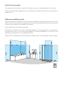
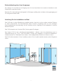
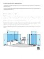
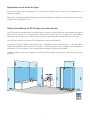
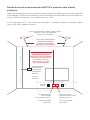
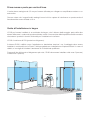
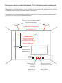
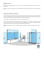
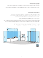
E120 can be tted into a bathroom environment, which is different to most other rooms in the home. The
nature of this wet environment is recognised by the respective standards authorities who test products
in terms of their suitability to be installed in such areas.
E120 compiles with IP54 (Ingress protection).
E120 system is dened as an ‘Extra Low Voltage Installation’, but the wiring needs to be installed in
accordance with ‘Part P’ of the Design and Installation of Electrical Installations. If in doubt, you are
advised to seek assistance from a qualied electrician.
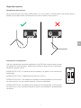
Please refer to the diagram below, E120 should be installed in either zone 2 (light blue) or zone 3 (white).
Bathroom installation guide

10
ENGLISH EN
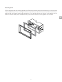
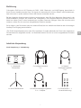
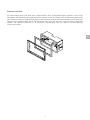
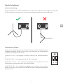
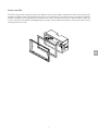
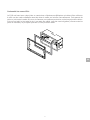
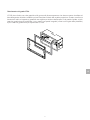
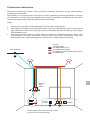
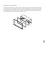
Reaching IP54:
E120 is supplied with two rubber gaskets of different thicknesses which should be stuck to the wall side
of the metal frame prior to screwing the frame to the back box. This will create a seal between the frame
and the wall and ensure better water protection. If the wall is at then the thinner 1mm gasket can be
used, for uneven walls (such as between tile joins) then the thicker 2.5mm gasket can be used.

11
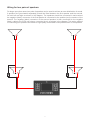
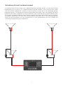
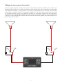
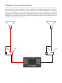
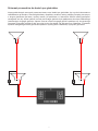
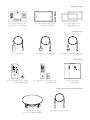
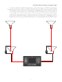
For larger open plan areas, two pairs of speakers can be used to achieve an even distribution of sound.
A speaker wire (purchased separately) should be tted between the rst speaker and the second,
for both left and right as shown in the diagram. The speakers should be connected in series where
the negative (black) connector of the rst speaker is connected to the positive (red) connector of the
second. The negative (black) connector of the second speaker is then connected to the negative
(black) cable to the E120 unit using a connector block, as shown in the diagram. This series method
of connecting two speakers will ensure a high quality and reliable sound performance of the speakers.
Wiring for two pairs of speakers

12
ENGLISH EN
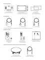
Second fix
Configurable Switches:
There are two small switches mounted on the lower PCB that adjust the audio mode
outputs. After making a switch position change you will need to power down the
E120.
SWITCH 1 OFF – Line output is variable, adjusts with amplier volume.
SWITCH 1 ON – Line output is xed at 100%
SWIITCH 2 OFF – Amplier speaker outputs are in stereo mode with separate left
and right channels.
SWITCH 2 ON – Amplier speaker outputs are in mono mode with both left and right
channels combined on both speaker outputs.
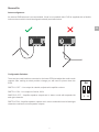
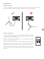
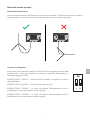
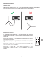
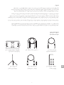
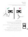
Antenna alignment:
An external DAB antenna is recommended, if that is not possible then E120 is supplied with a exible
indoor antenna which should be aligned vertically as shown below.

13
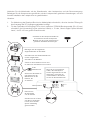
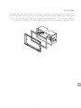
Connect cable tails to wall panel, speaker and power supply. Fix items in place using instructions
supplied with the speakers to ensure correct speaker installation.
Notes:
1. Blanking plate required to cover break out box, requires a single hole to exit DC extension cable.
2. Optional AUX input / TV sound requires a 25 x 50mm TOSLINK optical socket module (if using
optical cable), such as the ‘Nexxia Digital Optical Module Insert’ which is a 25x50mm slot in
module.
Connect speaker cables and t speakers
Follow installation instructions supplied with speakers
E120 wall panel
Fit supplied double gang
back box into wall.
Remove
protective lm
from Keypad.
Push in x4
gromits into the
small extraction
holes only after
testing the
system fully.
Plug in all cables then push
wall panel into the frame
untill it clicks into place.
Once satised that the system
is all connected and working
correctly, insert x4 rubber
grommets into the small holes
around the plastic edge.
Screw keypad mounting
frame into back box
using screws provided.
Do not over tighten and
distort the frame.
1 2
Mains
socket TV
Line-in

14
ENGLISH EN
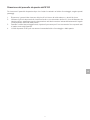
Removing the E120 wall panel
To remove the wall panel once it has been ‘clicked’ into the mounting frame follow these steps:
1. Remove the small rubber grommets from each of the small holes around the outer frame, keep
safe.
2. Use the small removal tool provided, or a similar tool 1.4mm diameter to insert into the hole, add
a little pressure into the frame whilst gently pulling the corresponding corner of the wall unit away
from the wall.
3. When the unit comes away slightly, repeat the process for the next hole until all four have been
released.
4. The E120 wall unit can now be removed away from the mounting frame and off the wall.

15
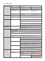
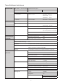
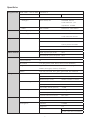
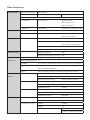
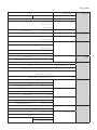
Specification
Audio Sources DAB / DAB+ / FM with RDS F-connector
Bluetooth Wireless BT 5.0 A2DP
AUX:
- Analogue 3.5mm stereo Sensitivity: 350mV
Max level: 1.5V
Impedence: 10kΩ
- Optical mini TOSLINK Resolution: 16bit 48kHz
Audio Outputs Speaker outputs Left & Right Stereo or dual mono
Analogue line 3.5mm stereo Modes: Fixed or variable
Max level: 670mV
Amplifier Class D Continuous power 2 x 25W @ 6Ω
THD 0.07% @ 1W
0.2% @ rated power
SNR >75dB @ Rated power
Frequency response 20Hz - 20kHz +/- 1dB
Ratings E120 wall panel IP54
Splash proof remote IP54
Control Touch sensitive buttons x 15
IR remote control x 13
BT AVRCP v1.6 (play, pause, skip, track, artist, album name)
Menu languages English, German, Dutch, French, Danish, Spanish
Italian, Norwegian, Polish, Finnish
Alarms x2 once, daily, weekdays, weekends
General Power supply Input 100 - 240V AC 50/60 Hz
Output 22V DC 1.5amps
Dimensions (HxWxD) 30mm x 50mm x 115mm
Power consumption Typical 10W
Standby <1W
Deep standby <0.5W
Wall panel Net weight 0.251kg
Dimensions (HxWxD) 91mm x 151mm x 33mm
Operating ambient temperature Max. 40 ºC
Cables Speaker cable Gauge 19 AWG
Lengths 2 x 7m
DC extension Gauge 16 AWG
Lengths 5m
Connectors 5.5mm x 2.5mm DC male
5.5mm x 2.5mm DC female

16
ENGLISH EN
Q Acoustics Media products are warranted free of defects in materials and workmanship for a period of 1 year from
the date of purchase. During the warranty period Q Acoustics will, at its option, repair or replace any product found to
be faulty after inspection by the company or its appointed distributor or agent.
Misuse and fair wear and tear are not covered by warranty.
Goods for repair should in the rst instance be returned to the supplying dealer. If this is not possible contact Q
Acoustics or their appointed distributor for your area to determine the correct warranty procedure. If possible the
original packaging should be used to return the product as damage sustained during transit to the repair centre is not
covered by the warranty. The warranty does not in any way affect your legal rights.
Warranty can be extended to 2 years by registering your product at www.qacoustics.co.uk/register.
For service information in other countries visit: www.qacoustics.co.uk
Q Acoustics
Armour Home Electronics Limited
Woodside 2, Dunmow Road
Bishops Stortford, Herts
CM23 5RG
Our policy is one of continuous product improvement.
We reserve the right to change the designs and specications without notice.
This document contains information that is subject to change without notice.
The Bluetooth® word mark and logo are registered trademarks owned by
Bluetooth SIG, Inc. and use of such marks by Armour Home Electronics
Limited is under license. Other trademarks and trade names are those of their
respective owners.
Warranty

1
Inhaltsverzeichnis
Wichtige Sicherheits- und Warnhinweise ............................................................................................ 2
Einführung ........................................................................................................................................... 4
Inhalt der Verpackung ......................................................................................................................... 4
E120 System-Schema ......................................................................................................................... 6
Positionierung des E120 und der Backboxes ..................................................................................... 7
Grundlegende Erstverkabelung .......................................................................................................... 8
Erstverkabelung des Line-Ausgangs .................................................................................................. 9
Anleitung für die Installation im Bad ................................................................................................... 9
Verkabelung für zwei Lautsprecherpaare ......................................................................................... 11
Zweite Verkabelung ........................................................................................................................... 12
Entfernen der E120-Wandkonsole .................................................................................................... 14
Technische Daten .............................................................................................................................. 15
Garantie ............................................................................................................................................. 16
La page est en cours de chargement...
La page est en cours de chargement...
La page est en cours de chargement...
La page est en cours de chargement...
La page est en cours de chargement...
La page est en cours de chargement...
La page est en cours de chargement...
La page est en cours de chargement...
La page est en cours de chargement...
La page est en cours de chargement...
La page est en cours de chargement...
La page est en cours de chargement...
La page est en cours de chargement...
La page est en cours de chargement...
La page est en cours de chargement...
La page est en cours de chargement...
La page est en cours de chargement...
La page est en cours de chargement...
La page est en cours de chargement...
La page est en cours de chargement...
La page est en cours de chargement...
La page est en cours de chargement...
La page est en cours de chargement...
La page est en cours de chargement...
La page est en cours de chargement...
La page est en cours de chargement...
La page est en cours de chargement...
La page est en cours de chargement...
La page est en cours de chargement...
La page est en cours de chargement...
La page est en cours de chargement...
La page est en cours de chargement...
La page est en cours de chargement...
La page est en cours de chargement...
La page est en cours de chargement...
La page est en cours de chargement...
La page est en cours de chargement...
La page est en cours de chargement...
La page est en cours de chargement...
La page est en cours de chargement...
La page est en cours de chargement...
La page est en cours de chargement...
La page est en cours de chargement...
La page est en cours de chargement...
La page est en cours de chargement...
La page est en cours de chargement...
La page est en cours de chargement...
La page est en cours de chargement...
La page est en cours de chargement...
La page est en cours de chargement...
La page est en cours de chargement...
La page est en cours de chargement...
La page est en cours de chargement...
La page est en cours de chargement...
La page est en cours de chargement...
La page est en cours de chargement...
La page est en cours de chargement...
La page est en cours de chargement...
La page est en cours de chargement...
La page est en cours de chargement...
La page est en cours de chargement...
La page est en cours de chargement...
La page est en cours de chargement...
La page est en cours de chargement...
La page est en cours de chargement...
La page est en cours de chargement...
La page est en cours de chargement...
La page est en cours de chargement...
La page est en cours de chargement...
La page est en cours de chargement...
La page est en cours de chargement...
La page est en cours de chargement...
La page est en cours de chargement...
La page est en cours de chargement...
La page est en cours de chargement...
La page est en cours de chargement...
La page est en cours de chargement...
La page est en cours de chargement...
La page est en cours de chargement...
La page est en cours de chargement...
La page est en cours de chargement...
La page est en cours de chargement...
La page est en cours de chargement...
La page est en cours de chargement...
La page est en cours de chargement...
La page est en cours de chargement...
La page est en cours de chargement...
La page est en cours de chargement...
La page est en cours de chargement...
La page est en cours de chargement...
La page est en cours de chargement...
La page est en cours de chargement...
La page est en cours de chargement...
La page est en cours de chargement...
La page est en cours de chargement...
La page est en cours de chargement...
-
 1
1
-
 2
2
-
 3
3
-
 4
4
-
 5
5
-
 6
6
-
 7
7
-
 8
8
-
 9
9
-
 10
10
-
 11
11
-
 12
12
-
 13
13
-
 14
14
-
 15
15
-
 16
16
-
 17
17
-
 18
18
-
 19
19
-
 20
20
-
 21
21
-
 22
22
-
 23
23
-
 24
24
-
 25
25
-
 26
26
-
 27
27
-
 28
28
-
 29
29
-
 30
30
-
 31
31
-
 32
32
-
 33
33
-
 34
34
-
 35
35
-
 36
36
-
 37
37
-
 38
38
-
 39
39
-
 40
40
-
 41
41
-
 42
42
-
 43
43
-
 44
44
-
 45
45
-
 46
46
-
 47
47
-
 48
48
-
 49
49
-
 50
50
-
 51
51
-
 52
52
-
 53
53
-
 54
54
-
 55
55
-
 56
56
-
 57
57
-
 58
58
-
 59
59
-
 60
60
-
 61
61
-
 62
62
-
 63
63
-
 64
64
-
 65
65
-
 66
66
-
 67
67
-
 68
68
-
 69
69
-
 70
70
-
 71
71
-
 72
72
-
 73
73
-
 74
74
-
 75
75
-
 76
76
-
 77
77
-
 78
78
-
 79
79
-
 80
80
-
 81
81
-
 82
82
-
 83
83
-
 84
84
-
 85
85
-
 86
86
-
 87
87
-
 88
88
-
 89
89
-
 90
90
-
 91
91
-
 92
92
-
 93
93
-
 94
94
-
 95
95
-
 96
96
-
 97
97
-
 98
98
-
 99
99
-
 100
100
-
 101
101
-
 102
102
-
 103
103
-
 104
104
-
 105
105
-
 106
106
-
 107
107
-
 108
108
-
 109
109
-
 110
110
-
 111
111
-
 112
112
-
 113
113
-
 114
114
-
 115
115
-
 116
116


dans d''autres langues
Documents connexes

Autres documents
-
Panasonic NV7000 Mode d'emploi
-
Yamaha NS-E120 Le manuel du propriétaire
-
ACOUSTICS FS75 Le manuel du propriétaire
-
Silvercrest SLS 2000 B2 Operating Instructions Manual
-
HP ENVY 120 e-All-in-One Printer Guide de démarrage rapide
-
Pure Acoustics DAP-601ES Manuel utilisateur
-
Dali ZENSOR 5 AX Le manuel du propriétaire
-
Acer E120 Manuel utilisateur
-
Arcam SOLO MUSIC SYSTEM Le manuel du propriétaire
-
Crosley TVee One Le manuel du propriétaire