
Operating Lnstructions
Integral XT
Process thermostats
XT 150, XT 250 W, XT 280, XT 280 W, XT 350 W, XT 350 HW, XT 490 W,
XT 550, XT 550 W, XT 750, XT 750 S, XT 750 H, XT 750 HS,
XT 950 W, XT 950 WS, XT 1590 W, XT 1590 WS,
XT 1850 W, XT 1850 WS
High-temperature thermostats
XT 4 H, XT 4 HW, XT 8 H, XT 8 HW


YAWE0028 Translation of the original operating instructions
release 07/2017 i
replaces release 11/2016 h, 06/2016 g6, 04/2016 g5,
01/2015 g4, 05/2013 g1, 02/2012 e3, 10/2011 d1, 08/2011 c4,
08/2011 c2, 05/2011 c1, 11/07/2009, 08/06/03/2008, 07/2007
Valid from:
software version of Command (Control Panel) 3.44
software version of Control system (Master) 2.46
software version of Security system (Master) 2.19
LAUDA DR. R. WOBSER GMBH & CO. KG
Pfarrstraße 41/43
97922 Lauda-K
önigshofen
Germany
software version of Chilling system 3.37
software version of Pump 2.20
software version of Analogue IO module 3.15
software version of Serial IO module 3.19
software version of Digital IO module 3.14
software version of Ethernet module 1.21
software version of EtherCAT module 1.03
Phone: +49 (0)9343 503-0
Fax: +49 (0)9343 503-
222
E-mail [email protected]
Internet http://www.lauda.de
Operating instructions
Process thermostats
XT 150, XT 250 W, XT 280, XT 280 W, XT 350 W, XT 350 HW, XT 490 W,
XT 550, XT 550 W, XT 750, XT 750 S, XT 750 H, XT 750 HS,
XT 950 W, XT 950 WS, XT 1590 W, XT 1590 WS,
XT 1850 W, XT 1850 WS
High-temperature thermostats
XT 4 H, XT 4 HW, XT 8 H, XT 8 HW
Read the instructions before starting work!


Integral XT
YAWE0028 / 28/07/2017 Prefixed safety notes 5
Prefixed safety notes
Before operating the equipment please read carefully all the instructions and safety
notes in Section 1.
If you have any questions please phone us!
Follow the instructions on setting up, operation etc. This is the only way to avoid incor-
rect operation of the equipment and to ensure full warranty protection.
• Transport the equipment with care!
The unit may NEVER be overturned nor put upside down!
• Equipment and its internal parts can be damaged:
− by dropping,
− by shock.
• Equipment must only be operated by technically qualified personnel!
• Never operate the equipment without the heat transfer liquid!
• Do not start up the equipment if,
− it is damaged or leaking,
− cable (not only supply cable) is damaged.
• Switch off the equipment and pull out the mains plug:
− for servicing or repair,
− moving the equipment!
• Drain the device before moving the equipment!
• Do not carry out any technical changes on the device!
• Have the equipment serviced or repaired by properly qualified personnel only!
The Operating Instructions include additional safety notes which are identified by a triangle with an
exclamation mark. Carefully read the instructions and follow them accurately! Disregarding the in-
structions may have serious consequences, such as damage to the equipment, damage to property
or injury to personnel!
We reserve the right to make technical alterations!

Integral XT
6 Contents YAWE0028 / 28/07/2017
Contents
Prefixed safety notes .................................................................................................................................... 5
1 SAFETY INSTRUCTIONS ................................................................................................................ 9
1.1 GENERAL SAFETY INSTRUCTIONS .......................................................................................................... 9
1.2 OTHER SAFETY INFORMATION ............................................................................................................. 10
2 BRIEF OPERATING INSTRUCTIONS ........................................................................................... 12
2.1 MENU STRUCTURE: MASTER .............................................................................................................. 13
2.2 MENU STRUCTURE: COMMAND ........................................................................................................... 14
2.3 VIEW OF THE DEVICE AND CONNECTIONS ............................................................................................. 15
3 CONTROLS AND FUNCTIONAL ELEMENTS .............................................................................. 23
4 DEVICE DESCRIPTION .................................................................................................................. 24
4.1 ENVIRONMENTAL CONDITIONS ............................................................................................................ 24
4.2 TYPES OF DEVICES ............................................................................................................................ 24
4.3 HYDRAULIC CIRCUIT AND VARIO PUMP ................................................................................................. 25
4.4 SUBSTANCES / MATERIALS .................................................................................................................. 25
4.5 TEMPERATURE DISPLAY, CONTROL AND SAFETY CIRCUIT ...................................................................... 25
4.6 PROGRAMMER AND RAMP FUNCTION ................................................................................................... 26
4.7 INTERFACES ...................................................................................................................................... 26
4.8 INTERFACE MODULES (ACCESSORIES) ................................................................................................. 27
4.9 REFRIGERATING UNIT ......................................................................................................................... 27
5 UNPACKING ................................................................................................................................... 28
5.1 AFTER UNPACKING ............................................................................................................................. 28
5.2 STANDARD ACCESSORIES: .................................................................................................................. 28
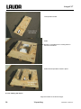
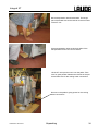
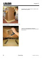
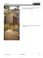
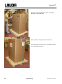
5.3 UNPACKING AND PACKING WITH ORIGINAL TRANSPORT PACKAGING MATERIAL ....................................... 29
5.3.1 Sector of application ........................................................................................................................ 29
5.3.2 Background ...................................................................................................................................... 29
5.3.3 Supposition ...................................................................................................................................... 29
5.3.4 Unpacking the device ....................................................................................................................... 29
5.3.5 Packing for shipping with original transport packaging material ...................................................... 29
5.3.5.1 Overview ................................................................................................................................... 29
5.3.5.2 Packing the device .................................................................................................................... 30
6 PREPARATIONS ............................................................................................................................ 35
6.1 ASSEMBLY AND SITING ....................................................................................................................... 35
6.2 HEAT TRANSFER LIQUIDS, COOLING WATER AND HOSES ....................................................................... 38
7 STARTING UP ................................................................................................................................ 41
7.1 MAINS CONNECTION ........................................................................................................................... 41
7.2 SWITCHING ON ................................................................................................................................... 42
7.3 SWITCHING OFF / STANDBY ................................................................................................................. 44
7.4 KEY FUNCTIONS ................................................................................................................................. 45
7.4.1 General key functions and pilot lamps ............................................................................................. 45
7.4.2 Changing window information .......................................................................................................... 50
7.4.3 Locking the keyboard ....................................................................................................................... 51
7.5 LEVEL DISPLAY .................................................................................................................................. 53
7.6 FILLING, VENTING AND DEGASSING ...................................................................................................... 54
7.6.1 Filling ................................................................................................................................................ 54
7.6.2 Venting ............................................................................................................................................. 55
7.6.3 Degassing ........................................................................................................................................ 56
7.6.3.1 Automatic degassing program .................................................................................................. 56

Integral XT
YAWE0028 / 28/07/2017 Contents 7
7.6.3.2 Permanently and automatic degassing ................................................................................... 57
7.6.4 Topping up ...................................................................................................................................... 57
7.7 DRAINING ......................................................................................................................................... 58
7.8 CHANGING THE HEAT TRANSFER LIQUID AND INTERNAL CLEANING ........................................................ 59
7.9 IMPORTANT SETTINGS ....................................................................................................................... 60
7.9.1 Temperature setpoint setting .......................................................................................................... 60
7.9.2 Displaying the actual external temperature .................................................................................... 62
7.9.3 Pump capacity or setting standby ................................................................................................... 63
7.9.4 Pressure control .............................................................................................................................. 65
7.9.5 Maximum pressure control .............................................................................................................. 65
7.9.6 Activating external control ............................................................................................................... 66
7.9.7 Current consumption from the mains .............................................................................................. 68
7.9.8 Setting the date and time ................................................................................................................ 69
7.9.9 Display resolution setting ................................................................................................................ 70
7.10 SPECIAL SETTINGS ............................................................................................................................ 71
7.10.1 Defining the type of start mode ....................................................................................................... 71
7.10.2 Defining temperature limits ............................................................................................................. 72
7.10.3 Setpoint offset operating mode ....................................................................................................... 73
7.10.4 Restoring works settings ................................................................................................................. 74
7.10.5 Setting the volume of the acoustic signals ...................................................................................... 75
7.10.6 Entering the offset of the internal temperature probe ..................................................................... 75
7.10.7 Restoring the works setting of the internal temperature-probe offset ............................................. 76
7.10.8 Entering the offset of the external temperature probe .................................................................... 77
7.10.9 Restoring the works setting of the external temperature-probe offset ............................................ 77
7.10.10 SmartCool ....................................................................................................................................... 78
7.11 GRAPHICAL DISPLAY OF TEMPERATURE MEASUREMENTS ..................................................................... 79
7.12 PROGRAMMER .................................................................................................................................. 81
7.12.1 Program example ............................................................................................................................ 81
7.12.2 Selecting and starting the program (Start, Hold, Stop) ................................................................... 83
7.12.3 Interrupting, continuing or terminating the program (Hold, Continue, Stop) ................................... 84
7.12.4 Creating or modifying a program (Edit) ........................................................................................... 85
7.12.5 Defining the number of program loops (Loops) .............................................................................. 89
7.12.6 Viewing the program sequence as a graph (Graph) ....................................................................... 89
7.12.7 Obtaining information on a program (Info) ...................................................................................... 90
7.12.8 Optimized programmer ................................................................................................................... 91
7.13 RAMP FUNCTION ............................................................................................................................... 92
7.14 TIMER FUNCTION / TIMER ................................................................................................................... 93
7.15 CONTROL AND CONTROL PARAMETERS .............................................................................................. 94
7.15.1 Setting instructions for bypass ........................................................................................................ 95
7.15.2 Configuration examples .................................................................................................................. 96
7.15.3 Internal control variable (integral measurement probe) .................................................................. 97
7.15.3.1 Procedure for setting the control parameters for internal control ............................................ 98
7.15.3.2 Table with control parameters and pump level for internal control .......................................... 98
7.15.4 External control variable (External measurement probe) ............................................................... 99
7.15.4.1 Procedure for setting the control parameters for external control ......................................... 100
7.15.4.2 Well-proven settings for control parameters and pump level for external control ................. 102
7.15.5 Internal and external control parameter sets ................................................................................ 102
7.15.6 Self Adaption ................................................................................................................................. 104
7.15.7 Limiting the heating and cooling power ......................................................................................... 106
7.15.7.1 Actuating signal limit .............................................................................................................. 106
7.15.7.2 Dynamic limitation of heating power ...................................................................................... 106
7.15.7.3 Dynamic control of heating power ......................................................................................... 107
7.16 ALARMS, WARNINGS AND ERRORS .................................................................................................. 108
7.16.1 Overtemperature protection and checking .................................................................................... 108
7.16.2 Low-level alarm and low-level checking ........................................................................................ 109
7.16.3 High-level settings ......................................................................................................................... 110
7.16.4 High-level warning or alarm .......................................................................................................... 111
7.16.5 Pump-motor supervision: Overload or blockage ........................................................................... 112

Integral XT
8 Contents YAWE0028 / 28/07/2017
7.16.6 Pump-motor supervision: Dry running ........................................................................................... 112
8 INTERFACE MODULES ............................................................................................................... 113
8.1 INSTALLING OF MODULES .................................................................................................................. 113
8.2 MENU STRUCTURE FOR ALL MODULES ............................................................................................... 115
8.3 SERIAL INTERFACES RS 232/485 (ONLY COMMAND REMOTE CONTROL OR MODULE) .......................... 116
8.3.1 Connecting cables and interface test RS 232................................................................................ 116
8.3.2 Protocol RS 232 ............................................................................................................................. 117
8.3.3 Connecting cable RS 485 .............................................................................................................. 118
8.3.4 Protocol RS 485 ............................................................................................................................. 118
8.3.5 Write commands (Data commands to the thermostat) .................................................................. 119
8.3.6 Read commands (Data requested from the thermostat) ............................................................... 120
8.3.7 Error messages .............................................................................................................................. 122
8.3.8 Driver-software for LABVIEW® ...................................................................................................... 122
8.4 ANALOGUE MODULE ......................................................................................................................... 123
8.5 CONTACT MODULE ........................................................................................................................... 125
8.5.1 Contact module LRZ 915 with three inputs and three outputs ...................................................... 125
8.5.2 Namur-Contact module LRZ 914 with only one input and one output ........................................... 126
9 MAINTENANCE ............................................................................................................................ 127
9.1 CLEANING ....................................................................................................................................... 127
9.1.1 Cleaning the surface of the device ................................................................................................ 127
9.1.2 Cleaning the hydraulic circuit ......................................................................................................... 127
9.1.3 Draining the water-cooled condenser ............................................................................................ 127
9.2 DEVICE STATUS ............................................................................................................................... 127
9.2.1 Interrogating the device type.......................................................................................................... 127
9.2.2 Software version ............................................................................................................................ 128
9.2.3 Serial numbers ............................................................................................................................... 128
9.2.4 Device data .................................................................................................................................... 128
9.2.5 Fault memory ................................................................................................................................. 129
9.2.6 Runnig time .................................................................................................................................... 129
9.2.7 Heater Info ..................................................................................................................................... 130
9.3 SERVICING AND REPAIR .................................................................................................................... 131
9.3.1 Service intervals ............................................................................................................................. 131
9.3.2 Cleaning the condenser ................................................................................................................. 132
9.3.2.1 Air-cooled condenser .............................................................................................................. 132
9.3.2.2 Water-cooled condenser......................................................................................................... 132
9.3.2.2.1 Cleaning the dirt trap ........................................................................................................... 132
9.3.2.2.2 Decalcifying the water cooling circuit .................................................................................. 133
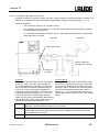
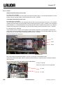
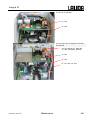
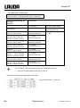
9.3.3 Fuses ............................................................................................................................................. 134
9.3.4 Testing the heat transfer liquid ...................................................................................................... 141
9.3.5 Repair information .......................................................................................................................... 141
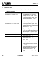
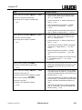
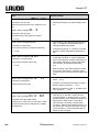
9.4 REMEDYING FAULTS ......................................................................................................................... 142
9.5 SERVICE, ORDERING REPLACEMENT PARTS AND RATING LABEL ........................................................... 146
9.6 DISPOSAL INFORMATION ................................................................................................................... 147
9.6.1 Disposal of the refrigerant .............................................................................................................. 147
9.6.2 Disposal of the packaging .............................................................................................................. 147
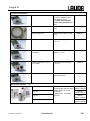
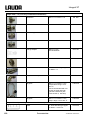
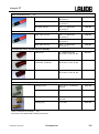
10 ACCESSORIES ............................................................................................................................ 148
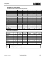
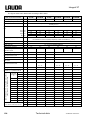
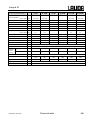
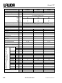
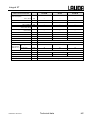
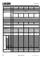
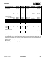
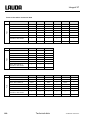
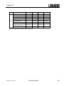
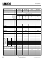
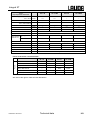
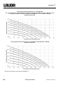
11 TECHNICAL DATA ....................................................................................................................... 152
12 INDEX ............................................................................................................................................ 165
CONFIRMATION

Integral XT
YAWE0028/ 28/07/2017 Safety instructions 9
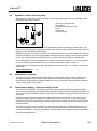
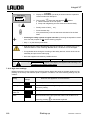
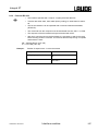
Explanation of signs:
Danger: This sign is used where there may be injury to person-
nel if a recommendation is not followed accurately or is
disregarded.
+
Note: Here special attention is drawn to some aspect. May
include reference to danger.
þ
Reference: Refers to other information in different sections.
1 Safety instructions
According to Paragraph 14 of the operational safety decree (BetrSichV)1, the device is a system which
requires supervision. (Classification according to the Pressure Equipment Directive 97/ 23 / EC: Catego-
ry I). Before being put into operation, the system must be subjected to inspection for siting, for ascer-
taining that the device is in order and for correct functioning. A certificate must be issued regarding this
inspection, documenting the extent and the result of the inspection.
1The national regulations of the respective country in which the system is sited must be followed.
1.1 General safety instructions
A process thermostat is used to heat, cool and circulate heat transfer liquids as specified. Hazards arise
from this due to high or low temperatures, excess pressures, fire and the general hazards due to the
application of electrical energy.
The user is largely protected by the application of the relevant standards.
Further hazard sources can arise from the type of material for which the temperature is to be stabilized,
e.g. by the exceeding or undercutting certain temperature thresholds or by the fracture of the container
and reaction with the heat transfer liquid.
It is not possible to include all possibilities. They remain essentially subject to the judgment and respon-
sibility of the operator.
The devices may only be used as intended, that is as described in this operating manual. This includes
operation by instructed specialist personnel.
The devices are not designed for use in medical applications in accordance with DIN EN 60601-1 or
IEC 601-1.
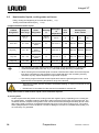
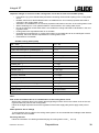
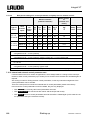
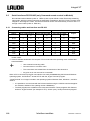
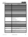
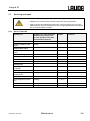
Classification in accordance with EMC requirements
Device Immunity Emissions class Customer power supply
Integral XT high-
temperature thermo-
stat
Type 2 in accordance
with
DIN EN 61326-1
Emissions Class B
in accordance with
CISPR 11
Worldwide
No limitation

Integral XT
10 Safety instructions YAWE0028 / 28/07/2017
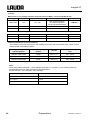
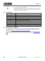
Classification in accordance with EMC requirements
Device Immunity Emissions class Customer power supply
Integral XT process
thermostat
single-phase and
triple-phase devices
Type 2 in accordance
with
DIN EN 61326-1
Emissions Class B
in accordance with
CISPR 11
Only for EU
Domestic connection value
≥ 100 A
Integral XT process
thermostat
single-phase and
triple-phase devices
Type 2 in accordance
with
DIN EN 61326-1
Emissions Class B
in accordance with
CISPR 11
Rest of the world (outside
EU)
No limitation
Valid for the USA:
Instructions for Class A digital devices
“This equipment has been tested and found to comply with the limits for Class A digital device, pursuant
to Part 15 of the FCC (Federal Communication Commission) Rules. These limits are designed to pro-
vide reasonable protection against harmful interference when the equipment is operated in a commer-
cial environment. This equipment generates, uses, and can radiate radio frequency energy and, if not
installed and used in accordance with the instruction manual, may cause harmful interference to radio
communications. Operation of this equipment in a residential area is likely to cause harmful interference
in which case the user will be required to correct the interference at his own expense.”
“This device complies with Part 15 of the FCC (Federal Communication Commission) Rules. Operation
is subject to the following two conditions: (1) This device may not cause harmful interference, and (2)
this device must accept any interference received, including interference that may cause undesired op-
eration.”
Valid for Canada:
“This Class A digital apparatus complies with Canadian ICES-003” (ICES = Interference Causing
Equipment Standards).
« Cet appareil numérique de la Classe A est conforme à la norme NMB-003 du Canada ».
1.2 Other safety information
• Check the device carefully for shipping damage before putting into operation. The device should not
be put into operation if shipping damage has been found.
• Only connect equipment to PE grounded mains sockets.
• At higher operating temperatures, parts of the device (e.g. connection, drain points) can take on sur-
face temperatures of over 70 °C. Be careful when touching the device à Danger of burns.
• After a mains failure or after switching off the device, the device surfaces can further heat up briefly.
• Use suitable hoses (þ 6.2).
• Check the hoses from time to time for any material fatigue. Hot liquid can escape due to hose fracture
and become a danger to personnel and materials.
• Heat transfer hoses and other hot parts must not come into contact with the mains cable.
• The following actions may start the thermostat unintentionally from the standby mode: Previously ac-
tivated timer mode (þ 7.14), "Start" command via interfaces (þ 8).
• Withdraw the mains plug before cleaning, servicing, repairing or moving the thermostat.
• Have repairs carried out only by specialists. The device may only be serviced by trained specialist
personnel.
• Keep to service and maintenance intervals (þ 9.2.6).
• Observe the permissible storage and operating temperatures (þ 11).
• The device should not be subjected to fire; otherwise there is the danger of an explosion.
• The device may only be operated with its housing in place.
• Do not site the device in areas where there are aggressive media.

Integral XT
YAWE0028/ 28/07/2017 Safety instructions 11
• Only site the device on a level surface.
• Do not put any heavy parts on the device.
• The operating personnel must wear suitable protective equipment.
• Do not operate the device when leaks have been found; ventilate the siting room immediately.
• With pressure sensitive loads (e.g. glass apparatus) with a maximum permissible operating pressure
below the maximum pressure of the pump (3.5 bars for water, with XT 1850 W 7.0 bars with water),
the hoses of the load must be routed such that kinking or squashing is not possible. In addition, a
separate safety valve must be installed to protect against faulty operation (þ 7.9.4, 7.9.5 and page
36).
• When selecting the heat transfer liquid, observe the permissible temperature range.
• Heat transfer liquids from LAUDA are recommended which have been tested for use with the device
(þ 6.2).
• Always set the over temperature cut-off point immediately according to the heat transfer liquid used
when filling (þ 7.16.1).
• If required, the heat transfer liquid should be checked for fitness for use (e.g. when changing the
method of operation), or half-yearly. Further use of the heat transfer liquid is only permissible if the in-
spection indicates this (þ 9.3.1 and 9.3.4).
• Keep the cover of the filling point closed during operation.
• Under certain operating conditions (degassing, rapid heating phases), the temperature may increase
in the expansion vessel. In extreme cases, the outflow temperature of the device is reached. If heat
transfer liquids are heated beyond a certain temperature (25 °C under the fire point of the heat trans-
fer liquid), then sources of ignition must be kept away from the filling opening and overflow (and at the
aeration point of the expansion tank). In such cases, a nitrogen overlay of the expansion vessel is
recommended (cover XT with connection for nitrogen overlay LWZ 072).
• Degas carefully (slowly) (þ 7.6.3).
• It is essential to avoid gas cushions in the load system. This can be done by reducing the pump pow-
er by one or two levels and checking that the level indication of the device does not increase.
• If an overflow catchments container is connected, it must be suitable (including the connecting hose)
for the maximum operating temperature. The connection hose must be securely fitted.
• The overflow must not be closed.
• Draining / drain mode is only permissible with an established temperature range (þ 7.7).
• During operation the drainage openings must be closed with plugs (standard accessories).
• On changing the heat transfer liquid, thoroughly clean the device and completely drain it. It is recom-
mended that the device is rinsed with the new heat transfer liquid (þ 7.8).
• It is essential to prevent the ingress of secondary liquids (e.g. via a customer's defective heat ex-
changer).
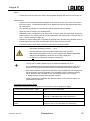
Safety instructions for water-cooled devices:
• The return hose of the water cooling must be securely fixed on the outlet port in order to prevent the
hose sliding off uncontrollably, also during pressure surges.
• The return hose of the water cooling must be fixed on the outlet port that hot cooling water cannot
splash out.
• It is essential to prevent kinking or squashing of the return hose for the water cooling. Excessive
pressure can cause the cooling water hoses to tear and hot water to escape.
• To prevent damages by a leakage of the cooling water system it’s recommended to use a leak-water
detector with shut-off valve (Aqua Stop).
Safety instructions for high-temperature thermostats with water counter-cooling:
• The High-temperature thermostats with cooling water connection (type W) always require a cooling
water supply, even if they are only used in heating mode.

Integral XT
12 Brief operating instructions YAWE0028 / 28/07/2017
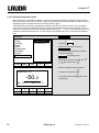
2 Brief operating instructions
These brief instructions shall give you the possibility to operate the unit quickly.
For safe operation of the unit, it is absolutely necessary to read carefully all the instruc-
tions and safety notes!
1. Set up the device or complete the configuration as required (þ 6.1).
The device should never be tilted or stood upside down!
Note the connection of the hose joints (þ 6.2).
2. Pay attention to pressure sensitive loads (e.g. glass apparatus) with a maximum permissi-
ble operating pressure (þ 7.9.4).
3. Only operate the Integral XT when flow through the external load is possible.
4. Open any shut-off valves in the external loads.
5. Compare the details on the rating label with the mains voltage.
Three-phase device: Ensure a clockwise phase sequence.
Only XT 1850 W Order No. LWP 732 and XT 1590 W Order No. LWP 742:
Check the switch position [400 V; 3/PE; 50 Hz or 440-480 V; 3/PE; 60 Hz] for presence of
mains voltage and frequency. An incorrect setting does not result in any damage, but an
error message occurs Error 367 (þ 9.4). With the unit switched off, set the in-
correctly set switch to the correct voltage and frequency values. The switch is fitted on the
back of the unit at the top left, behind the cover panel (þ 2.3).
6. Only connect device to a socket having a safety earth conductor.
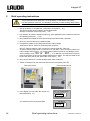
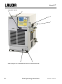
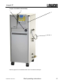
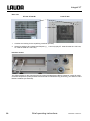
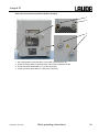
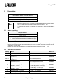
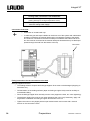
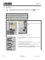
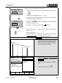
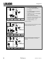
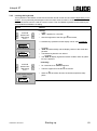
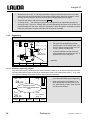
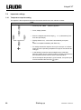
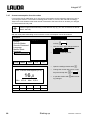
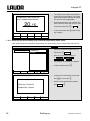
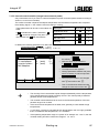
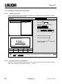
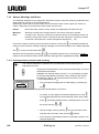
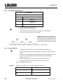
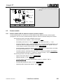
7. Switch on the device by the main fuse-switch on the front panel ("ON = l").
Bench-top device
Floor-standing device
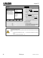
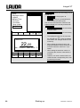
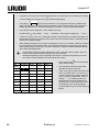
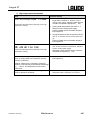
8. In the display you see either the current out-
flow temperature , e.g.:
or if the device has not yet been filled:
Act. val. outflow temp.
02%32
°C
Fill device
FiLL
°C

Integral XT
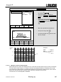
YAWE0028 / 28/07/2017 Brief operating instructions 13
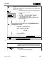
If instead, a warning or error message is displayed, then refer to Section 7.16.
9. Fill device with heat transfer liquid and follow Section 7.6.
Use suitable heat transfer liquid (þ 6.2).
The devices are rated for operation with non-flammable and flammable liquids according to
DIN EN 61010-2-010.
Water is not permissible!!
10. Set the over temperature cut-off point with according to the heat transfer liquid used
(þ 7.16.1).
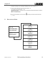
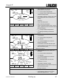
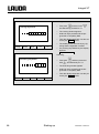
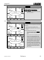
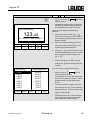
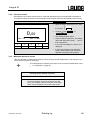
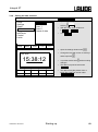
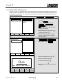
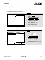
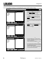
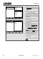
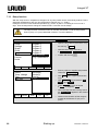
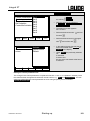
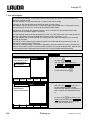
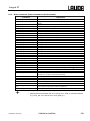
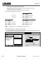
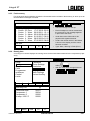
2.1 Menu structure: Master
25.32
This shows the actual
value of outflow tempera-
ture or actual value of
external temperature.
Fill
Filling mode, superim-
posed as required.
SEt
Set setpoint
Section 7.9.1.
Pu
Pump power
Section 7.9.3.
LE
Level indication
Section 7.5.
P
Pump pressure
Section 7.9.4.
Con
Control Int/Ext
Section 7.9.5.
F or Fill
Filling mode
Section 7.6.
unFill
Draining
Section 7.7.

Integral XT
14 Brief operating instructions YAWE0028 / 28/07/2017
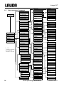
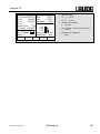
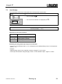
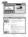
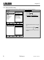
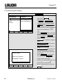
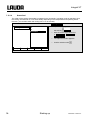
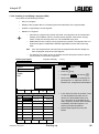
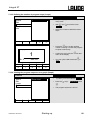
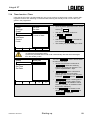
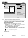
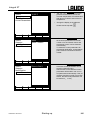
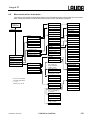
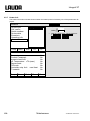
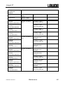
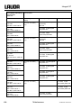
2.2 Menu structure: Command
Menu
Display
Sounds Master
Sounds Command
Language
Master mode
Autostart
Current consumpt.
Pump
Settings
Graph
Clock
Programmer
Interfaces 1
Control
Limits
Pump Level
Pressure control
Start Fill mode
Start Unfill mode
Max. Press.[bar] 1,0
Start unfill heat exch.
Aux. Pump OFF
Calibration
Works settings
Resolution
Device status
Display data
Basic settings
Overlevel handling
Set time
Set data
Format of date
Timer 1
Timer 2
Program 1
Program 2
Program 3
Program 4
Program 5
Ramp function
prog.Optimization
Serial Command
serial Master 2/
Profibus
Analog interfaces
Switching contact
Smart Cool 4
Control parameters
Control para. sets
Tv manual/auto
Correction limitation
Self Adaption
Control variable
Control parameters
Setpoint offset
Controller outp. limit
dynamic heat limit
HT Cooler Mode
3
HT Cooler min. Temp 3
Brightness
Contrast
intern Pt100
extern Pt100
Device type
Software Version
Serial numbers
Device data
Errorstore
Operating info
Heater Info
Status
Temp. Change
Time
Time unit
internal
external Pt100
Analog interface
extern serial
Calibration
Default
Alarm
Warning
Display
Basic window
Standard window
Super window
Edit
Default
T il (min)
T ih (max)
Xp
Tn
Tv (auto)
Td (auto)
Kpe
Tne
Tve (auto)
Tde (auto)
Xpf
Prop_E(a)
off
external Pt100
Status
Edit
Loops
Graph
Info
Start / Stop
Hold / continue
Modify
Erase
Show chart
Offset source
Setpoint offset
Automatic
Manual
Status
Setpoint
Identification
Actual Parameters
All Modules
Master
Command
Cool
Pump
Other connected
modules
English
Deutsch
Français
Español
All default
Only control par. int.
Only control par. ext.
Only miscellaneous
Settings
Mode
Displayed value
Legend
Sample Time
Time axis
Time base
Temp. scale
Limits
off
on
automatic
none
Warning
Warn.+ Heater off
Alarm
Mode
Baud rate
RS 485 address
all default
max. Cool
max. Heat
off
on
on
Start
End
Set value
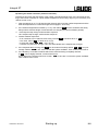
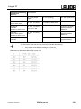
1 (
þ
8.2)
2 no menu in Command
3 only HT-Devices
4 not at XT 4 H, XT 8 H

Integral XT
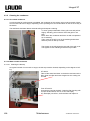
YAWE0028 / 28/07/2017 Brief operating instructions 15
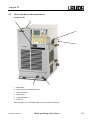
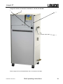
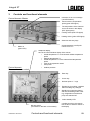
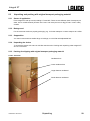
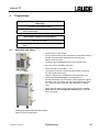
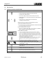
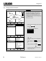
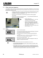
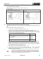
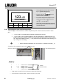
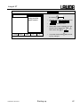
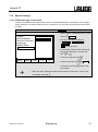
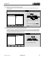
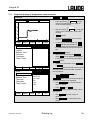
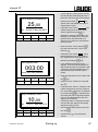
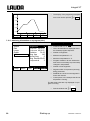
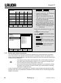
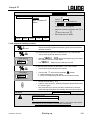
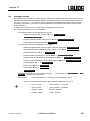
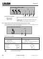
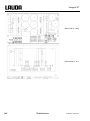
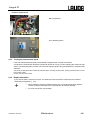
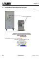
2.3 View of the device and connections
Integral XT 150
1 2
3
4
6 5
1 Main switch
2 Filling point for heat transfer liquid
3 Interface section
4 Mains cable
5 Drain point M16 x 1
6 Drain tap
Refer to page 21 for an illustrated side view of connections and taps.


Integral XT
20 Brief operating instructions YAWE0028 / 28/07/2017
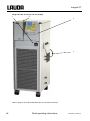
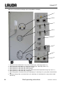
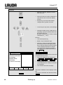
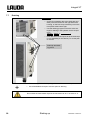
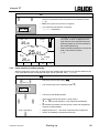
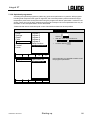
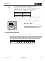
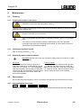
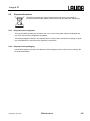
Rear view
XT 150/ XT 250 W from XT 280
1
2
1 Overflow and venting for the equalizing container (all units)
2 Switch for setting mains voltage and frequency (þ 2 and 9.4) (only XT 1850 W Order No. LWP 732;
XT 1590 W Order No. LWP 742).
Interface section
Two LiBus sockets for the Command remote control (standard) and LiBus accessories, socket for exter-
nal Pt100 temperature probe (resistance thermometer to DIN EN 60751) (accessory), two slots for LiBus
interface modules (accessories).
La page est en cours de chargement...
La page est en cours de chargement...
La page est en cours de chargement...
La page est en cours de chargement...
La page est en cours de chargement...
La page est en cours de chargement...
La page est en cours de chargement...
La page est en cours de chargement...
La page est en cours de chargement...
La page est en cours de chargement...
La page est en cours de chargement...
La page est en cours de chargement...
La page est en cours de chargement...
La page est en cours de chargement...
La page est en cours de chargement...
La page est en cours de chargement...
La page est en cours de chargement...
La page est en cours de chargement...
La page est en cours de chargement...
La page est en cours de chargement...
La page est en cours de chargement...
La page est en cours de chargement...
La page est en cours de chargement...
La page est en cours de chargement...
La page est en cours de chargement...
La page est en cours de chargement...
La page est en cours de chargement...
La page est en cours de chargement...
La page est en cours de chargement...
La page est en cours de chargement...
La page est en cours de chargement...
La page est en cours de chargement...
La page est en cours de chargement...
La page est en cours de chargement...
La page est en cours de chargement...
La page est en cours de chargement...
La page est en cours de chargement...
La page est en cours de chargement...
La page est en cours de chargement...
La page est en cours de chargement...
La page est en cours de chargement...
La page est en cours de chargement...
La page est en cours de chargement...
La page est en cours de chargement...
La page est en cours de chargement...
La page est en cours de chargement...
La page est en cours de chargement...
La page est en cours de chargement...
La page est en cours de chargement...
La page est en cours de chargement...
La page est en cours de chargement...
La page est en cours de chargement...
La page est en cours de chargement...
La page est en cours de chargement...
La page est en cours de chargement...
La page est en cours de chargement...
La page est en cours de chargement...
La page est en cours de chargement...
La page est en cours de chargement...
La page est en cours de chargement...
La page est en cours de chargement...
La page est en cours de chargement...
La page est en cours de chargement...
La page est en cours de chargement...
La page est en cours de chargement...
La page est en cours de chargement...
La page est en cours de chargement...
La page est en cours de chargement...
La page est en cours de chargement...
La page est en cours de chargement...
La page est en cours de chargement...
La page est en cours de chargement...
La page est en cours de chargement...
La page est en cours de chargement...
La page est en cours de chargement...
La page est en cours de chargement...
La page est en cours de chargement...
La page est en cours de chargement...
La page est en cours de chargement...
La page est en cours de chargement...
La page est en cours de chargement...
La page est en cours de chargement...
La page est en cours de chargement...
La page est en cours de chargement...
La page est en cours de chargement...
La page est en cours de chargement...
La page est en cours de chargement...
La page est en cours de chargement...
La page est en cours de chargement...
La page est en cours de chargement...
La page est en cours de chargement...
La page est en cours de chargement...
La page est en cours de chargement...
La page est en cours de chargement...
La page est en cours de chargement...
La page est en cours de chargement...
La page est en cours de chargement...
La page est en cours de chargement...
La page est en cours de chargement...
La page est en cours de chargement...
La page est en cours de chargement...
La page est en cours de chargement...
La page est en cours de chargement...
La page est en cours de chargement...
La page est en cours de chargement...
La page est en cours de chargement...
La page est en cours de chargement...
La page est en cours de chargement...
La page est en cours de chargement...
La page est en cours de chargement...
La page est en cours de chargement...
La page est en cours de chargement...
La page est en cours de chargement...
La page est en cours de chargement...
La page est en cours de chargement...
La page est en cours de chargement...
La page est en cours de chargement...
La page est en cours de chargement...
La page est en cours de chargement...
La page est en cours de chargement...
La page est en cours de chargement...
La page est en cours de chargement...
La page est en cours de chargement...
La page est en cours de chargement...
La page est en cours de chargement...
La page est en cours de chargement...
La page est en cours de chargement...
La page est en cours de chargement...
La page est en cours de chargement...
La page est en cours de chargement...
La page est en cours de chargement...
La page est en cours de chargement...
La page est en cours de chargement...
La page est en cours de chargement...
La page est en cours de chargement...
La page est en cours de chargement...
La page est en cours de chargement...
La page est en cours de chargement...
La page est en cours de chargement...
La page est en cours de chargement...
La page est en cours de chargement...
La page est en cours de chargement...
La page est en cours de chargement...
La page est en cours de chargement...
La page est en cours de chargement...
La page est en cours de chargement...
La page est en cours de chargement...
La page est en cours de chargement...
La page est en cours de chargement...
La page est en cours de chargement...
La page est en cours de chargement...
La page est en cours de chargement...
-
 1
1
-
 2
2
-
 3
3
-
 4
4
-
 5
5
-
 6
6
-
 7
7
-
 8
8
-
 9
9
-
 10
10
-
 11
11
-
 12
12
-
 13
13
-
 14
14
-
 15
15
-
 16
16
-
 17
17
-
 18
18
-
 19
19
-
 20
20
-
 21
21
-
 22
22
-
 23
23
-
 24
24
-
 25
25
-
 26
26
-
 27
27
-
 28
28
-
 29
29
-
 30
30
-
 31
31
-
 32
32
-
 33
33
-
 34
34
-
 35
35
-
 36
36
-
 37
37
-
 38
38
-
 39
39
-
 40
40
-
 41
41
-
 42
42
-
 43
43
-
 44
44
-
 45
45
-
 46
46
-
 47
47
-
 48
48
-
 49
49
-
 50
50
-
 51
51
-
 52
52
-
 53
53
-
 54
54
-
 55
55
-
 56
56
-
 57
57
-
 58
58
-
 59
59
-
 60
60
-
 61
61
-
 62
62
-
 63
63
-
 64
64
-
 65
65
-
 66
66
-
 67
67
-
 68
68
-
 69
69
-
 70
70
-
 71
71
-
 72
72
-
 73
73
-
 74
74
-
 75
75
-
 76
76
-
 77
77
-
 78
78
-
 79
79
-
 80
80
-
 81
81
-
 82
82
-
 83
83
-
 84
84
-
 85
85
-
 86
86
-
 87
87
-
 88
88
-
 89
89
-
 90
90
-
 91
91
-
 92
92
-
 93
93
-
 94
94
-
 95
95
-
 96
96
-
 97
97
-
 98
98
-
 99
99
-
 100
100
-
 101
101
-
 102
102
-
 103
103
-
 104
104
-
 105
105
-
 106
106
-
 107
107
-
 108
108
-
 109
109
-
 110
110
-
 111
111
-
 112
112
-
 113
113
-
 114
114
-
 115
115
-
 116
116
-
 117
117
-
 118
118
-
 119
119
-
 120
120
-
 121
121
-
 122
122
-
 123
123
-
 124
124
-
 125
125
-
 126
126
-
 127
127
-
 128
128
-
 129
129
-
 130
130
-
 131
131
-
 132
132
-
 133
133
-
 134
134
-
 135
135
-
 136
136
-
 137
137
-
 138
138
-
 139
139
-
 140
140
-
 141
141
-
 142
142
-
 143
143
-
 144
144
-
 145
145
-
 146
146
-
 147
147
-
 148
148
-
 149
149
-
 150
150
-
 151
151
-
 152
152
-
 153
153
-
 154
154
-
 155
155
-
 156
156
-
 157
157
-
 158
158
-
 159
159
-
 160
160
-
 161
161
-
 162
162
-
 163
163
-
 164
164
-
 165
165
-
 166
166
-
 167
167
-
 168
168
-
 169
169
-
 170
170
-
 171
171
-
 172
172


dans d''autres langues
Autres documents
-
Trox X-CUBE X2 Mode d'emploi
-
 Hach 6120118 Manuel utilisateur
-
Airwell PAC BT Series Guide d'installation
-
 Olimpia Splendid Sherpa 8M Le manuel du propriétaire
-
-
MKS T3PIA Manuel utilisateur
-
salmson Ixens D Mode d'emploi
-
Appro Dionex UltiMate 3000 Series Mode d'emploi
-
Eurotherm 2116/2132 Le manuel du propriétaire
-
Ingersoll-Rand R55 Manuel utilisateur

