Flex FX3181 Manuel utilisateur
- Catégorie
- Outils électroportatifs
- Taper
- Manuel utilisateur

For English
Version
See page 2
◆
Version
française
Voir page 22
◆
Versión en
español
Ver la página 43
833-FLEX-496
(833-3539-496)
OPERATOR’S MANUAL
MANUAL DEL OPERADOR
MANUEL DE L’UTILISATEUR
www.Registermyex.com
Contact Us /
Nous contacter /
Contáctenos
BRUSHLESS 24V, 5" (125MM) VARIABLE SPEED / FIXED SPEED ANGLE
GRINDER
MEULEUSES D’ANGLES À VITESSE VARIABLE / VITESSE FIXE SANS
BALAI DE 24 V, 125 MM
AMOLADORA ANGULAR DE VELOCIDAD VARIABLE / VELOCIDAD FIJA
SIN ESCOBILLAS DE 24 V Y 125 MM
FX3181/FX3181A
Model:
Modelo:
Modèle:

-2-
SAFETY SYMBOLS
The purpose of safety symbols is to attract your attention to possible dangers. The safety symbols
and the explanations with them deserve your careful attention and understanding. The symbol
warnings do not, by themselves, eliminate any danger. The instructions and warnings they give are
no substitutes for proper accident prevention measures.
WARNING Be sure to read and understand all safety instructions in this Owner's Manual,
including all safety alert symbols such as "DANGER," "WARNING," and
"CAUTION" before using this tool. Failure to follow all instructions listed below may result in electric
shock, re, and/or serious personal injury.
The denitions below describe the level of severity for each signal word. Please read the manual and
pay attention to these symbols.
This is the safety alert symbol. It is used to alert you to potential personal
injury hazards. Obey all safety messages that follow this symbol to avoid
possible injury or death.
DANGER DANGER indicates a hazardous situation which, if not avoided, will result in
death or serious injury.
WARNING WARNING indicates a hazardous situation which, if not avoided, could result
in death or serious injury.
CAUTION CAUTION, used with the safety alert symbol, indicates a hazardous situation
which, if not avoided, will result in minor or moderate injury.
Damage Prevention and Information Messages
These inform the user of important information and/or instructions that could lead to equipment or
other property damage if they are not followed. Each message is preceded by the word "NOTICE",
as in the example below:
NOTICE: Equipment and/or property damage may result if these instructions are not followed.
WARNING The operation of any power tools can result in foreign
objects being thrown into your eyes, which can result in
severe eye damage. Before beginning power tool operation, always wear
safety goggles or safety glasses with side shields and a full face shield when
needed. We recommend a Wide Vision Safety Mask for use over eyeglasses
or standard safety glasses with side shields. Always use eye protection which
is marked to comply with ANSI Z87.1.

-3-
GENERAL POWER TOOL SAFETY WARNINGS
WARNING Read all safety warnings, instructions, illustrations and specications
provided with this power tool. Failure to follow all instructions listed below may
result in electric shock, re and/or serious injury.
SAVE ALL WARNINGS AND INSTRUCTIONS FOR FUTURE REFERENCE.
The term “power tool” in the warnings refers to your mains-operated (corded) power tool or battery-
operated (cordless) power tool.
Work area safety
Keep work area clean and well lit. Cluttered
or dark areas invite accidents.
Do not operate power tools in explosive
atmospheres, such as in the presence of
ammable liquids, gases or dust. Power
tools create sparks which may ignite the dust or
fumes.
Keep children and bystanders away while
operating a power tool. Distractions can cause
you to lose control.
Electrical safety
Power tool plugs must match the outlet.
Never modify the plug in any way. Do
not use any adapter plugs with earthed
(grounded) power tools. Unmodied plugs
and matching outlets will reduce risk of electric
shock.
Avoid body contact with earthed or
grounded surfaces, such as pipes, radiators,
ranges and refrigerators. There is an
increased risk of electric shock if your body is
earthed or grounded.
Do not expose power tools to rain or wet
conditions. Water entering a power tool will
increase the risk of electric shock.
Do not abuse the cord. Never use the cord
for carrying, pulling or unplugging the
power tool. Keep cord away from heat, oil,
sharp edges or moving parts. Damaged or
entangled cords increase the risk of electric
shock.
When operating a power tool outdoors, use
an extension cord suitable for outdoor use.
Use of a cord suitable for outdoor use reduces
the risk of electric shock.
If operating a power tool in a damp location
is unavoidable, use a ground fault circuit
interrupter (GFCI) protected supply. Use of a
GFCI reduces the risk of electric shock.
Personal safety
Stay alert, watch what you are doing and
use common sense when operating a power
tool. Do not use a power tool while you are
tired or under the inuence of drugs, alcohol
or medication. A moment of inattention while
operating power tools may result in serious
personal injury.
Use personal protective equipment. Always
wear eye protection. Protective equipment
such as a dust mask, non-skid safety shoes,
hard hat or hearing protection used for
appropriate conditions will reduce personal
injuries.
Prevent unintentional starting. Ensure
the switch is in the off-position before
connecting to power source and/or battery
pack, picking up or carrying the tool.
Carrying power tools with your nger on the
switch or energizing power tools that have the
switch on invites accidents.
Remove any adjusting key or wrench before
turning the power tool on. A wrench or a key
left attached to a rotating part of the power tool
may result in personal injury.
Do not overreach. Keep proper footing
and balance at all times. This enables
better control of the power tool in unexpected
situations.
Dress properly. Do not wear loose clothing
or jewelry. Keep your hair and clothing away
from moving parts. Loose clothes, jewelry or
long hair can be caught in moving parts.
If devices are provided for the connection
of dust extraction and collection facilities,
ensure these are connected and properly
used. Use of dust collection can reduce dust-
related hazards.

-4-
Do not let familiarity gained from frequent
use of tools allow you to become
complacent and ignore tool safety
principles. A careless action can cause severe
injury within a fraction of a second.
Power tool use and care
Do not force the power tool. Use the correct
power tool for your application. The correct
power tool will do the job better and safer at the
rate for which it was designed.
Do not use the power tool if the switch
does not turn it on and off. Any power tool
that cannot be controlled with the switch is
dangerous and must be repaired.
Disconnect the plug from the power
source and/or remove the battery pack,
if detachable, from the power tool before
making any adjustments, changing
accessories, or storing power tools. Such
preventive safety measures reduce the risk of
starting the power tool accidentally.
Store idle power tools out of the reach of
children and do not allow persons unfamiliar
with the power tool or these instructions
to operate the power tool. Power tools are
dangerous in the hands of untrained users.
Maintain power tools and accessories.
Check for misalignment or binding of
moving parts, breakage of parts and any
other condition that may affect the power
tool’s operation. If damaged, have the power
tool repaired before use. Many accidents are
caused by poorly maintained power tools.
Keep cutting tools sharp and clean. Properly
maintained cutting tools with sharp cutting
edges are less likely to bind and are easier to
control.
Use the power tool, accessories and
tool bits etc. in accordance with these
instructions, taking into account the working
conditions and the work to be performed.
Use of the power tool for operations different
from those intended could result in a hazardous
situation.
Keep handles and grasping surfaces dry,
clean and free from oil and grease. Slippery
handles and grasping surfaces do not allow
for safe handling and control of the tool in
unexpected situations.
Battery tool use and care
Recharge only with the charger specied by
the manufacturer. A charger that is suitable for
one type of battery pack may create a risk of re
when used with another battery pack.
Use power tools only with specically
designated battery packs. Use of any other
battery packs may create a risk of injury and
re.
When battery pack is not in use, keep it
away from other metal objects, like paper
clips, coins, keys, nails, screws or other
small metal objects, that can make a
connection from one terminal to another.
Shorting the battery terminals together may
cause burns or a re.
Under abusive conditions, liquid may be
ejected from the battery; avoid contact.
If contact accidentally occurs, ush with
water. If liquid contacts eyes, additionally
seek medical help. Liquid ejected from the
battery may cause irritation or burns.
Do not use a battery pack or tool that is
damaged or modied. Damaged or modied
batteries may exhibit unpredictable behavior
resulting in re, explosion or risk of injury.
Do not expose a battery pack or tool to
re or excessive temperature. Exposure to
re or temperature above 265 °F may cause
explosion.
Follow all charging instructions and do
not charge the battery pack or tool outside
the temperature range specied in the
instructions. Charging improperly or at
temperatures outside the specied range may
damage the battery and increase the risk of re.
Service
Have your power tool serviced by a
qualied repair person using only identical
replacement parts. This will ensure that the
safety of the power tool is maintained.
Never service damaged battery packs.
Service of battery packs should only be
performed by the manufacturer or authorized
service providers

-5-
SAFETY WARNINGS COMMON FOR GRINDING, ABRASIVE
CUTTING-OFF OPERATIONS
This power tool is intended to function as
a grinder or cut-off tool. Read all safety
warnings, instructions, illustrations and
specications provided with this power tool.
Failure to follow all instructions listed below may
result in electric shock, re and/or serious injury.
Operations such as sanding, wire brushing
and polishing are not recommended to be
performed with this power tool. Operations
for which the power tool was not designed may
create a hazard and cause personal injury.
Do not use accessories which are not
specically designed and recommended
by the tool manufacturer. Just because the
accessory can be attached to your power tool, it
does not assure safe operation.
The rated speed of the accessory must be at
least equal to the maximum speed marked
on the power tool. Accessories running faster
than their rated speed can break and y apart.
The outside diameter and the thickness of
your accessory must be within the capacity
rating of your power tool. Incorrectly sized
accessories cannot be adequately guarded or
controlled.
Threaded mounting of accessories must
match the grinder spindle thread. For
accessories mounted by ange, the arbor
hole of the accessory must t the locating
diameter of the ange. Accessories that do not
match the mounting hardware of the power tool
will run out of balance, vibrate excessively and
may cause loss of control.
Do not use a damaged accessory. Before
each use, inspect the accessory such as
abrasive wheels for chips and cracks,
backing pad for cracks, tear or excess
wear, wire brush for loose or cracked wires.
If power tool or accessory is dropped,
inspect for damage or install an undamaged
accessory. After inspecting and installing
an accessory, position yourself and
bystanders away from the plane of the
rotating accessory and run the power tool
at maximum no-load speed for one minute.
Damaged accessories will normally break apart
during this test time.
Wear personal protective equipment.
Depending on application, use face
shield, safety goggles or safety glasses.
As appropriate, wear dust mask, hearing
protectors, gloves and workshop apron
capable of stopping small abrasive or
workpiece fragments. The eye protection must
be capable of stopping ying debris generated
by various operations. The dust mask or
respirator must be capable of ltrating particles
generated by your operation. Prolonged
exposure to high intensity noise may cause
hearing loss.
Keep bystanders a safe distance away from
work area. Anyone entering the work area
must wear personal protective equipment.
Fragments of workpiece or of a broken
accessory may y away and cause injury
beyond immediate area of operation.
Hold the power tool by insulated gripping
surfaces only, when performing an operation
where the cutting tool may contact hidden
wiring. Contact with a “live” wire will also make
exposed metal parts of the power tool “live” and
could give the operator an electric shock.
Never lay the power tool down until the
accessory has come to a complete stop. The
spinning accessory may grab the surface and
pull the power tool out of your control.
Do not run the power tool while carrying it at
your side. Accidental contact with the spinning
accessory could snag your clothing, pulling the
accessory into your body.
Regularly clean the power tool’s air vents.
The motor’s fan will draw the dust inside
the housing and excessive accumulation of
powdered metal may cause electrical hazards.
Do not operate the power tool near
ammable materials. Sparks could ignite these
materials.
Do not use accessories that require liquid
coolants. Using water or other liquid coolants
may result in electrocution or shock.

-6-
Further safety instructions for all
operations
Kickback and Related Warnings:
Kickback is a sudden reaction to a pinched or
snagged rotating wheel, backing pad, brush
or any other accessory. Pinching or snagging
causes rapid stalling of the rotating accessory
which in turn causes the uncontrolled power
tool to be forced in the direction opposite of the
accessory’s rotation at the point of the binding.
For example, if an abrasive wheel is snagged or
pinched by the workpiece, the edge of the wheel
that is entering into the pinch point can dig into
the surface of the material causing the wheel to
climb out or kick out. The wheel may either jump
toward or away from the operator, depending on
direction of the wheel’s movement at the point
of pinching. Abrasive wheels may also break
under these conditions.
Kickback is the result of power tool misuse
and/or incorrect operating procedures or
conditions and can be avoided by taking proper
precautions as given below.
Maintain a rm grip on the power tool
and position your body and arm to allow
you to resist kickback forces. Always use
auxiliary handle, if provided, for maximum
control over kickback or torque reaction
during start-up. The operator can control
torque reactions or kickback forces, if proper
precautions are taken.
Never place your hand near the rotating
accessory. Accessory may kickback over your
hand.
Do not position your body in the area where
power tool will move if kickback occurs.
Kickback will propel the tool in direction
opposite to the wheel’s movement at the point
of snagging.
Use special care when working corners,
sharp edges etc. Avoid bouncing and
snagging the accessory. Corners, sharp
edges or bouncing have a tendency to snag the
rotating accessory and cause loss of control or
kickback.
Do not attach a saw chain woodcarving
blade or toothed saw blade. Such blades
create frequent kickback and loss of control.
SAFETY WARNINGS SPECIFIC FOR GRINDING AND ABRASIVE
CUTTING-OFF OPERATIONS
Use only wheel types that are recommended
for your power tool and the specic guard
designed for the selected wheel. Wheels for
which the power tool was not designed cannot
be adequately guarded and are unsafe.
The grinding surface of centre depressed
wheels must be mounted below the plane of
the guard lip. An improperly mounted wheel
that projects through the plane of the guard lip
cannot be adequately protected.
The guard must be securely attached to the
power tool and positioned for maximum
safety, so the least amount of wheel is
exposed towards the operator. The guard
helps to protect the operator from broken wheel
fragments, accidental contact with wheel and
sparks that could ignite clothing.
Wheels must be used only for recommended
applications. For example: do not grind with
the side of cut-off wheel. Abrasive cut-off
wheels are intended for peripheral grinding, side
forces applied to these wheels may cause them
to shatter.
Always use undamaged wheel anges
that are of correct size and shape for your
selected wheel. Proper wheel anges support
the wheel thus reducing the possibility of wheel
breakage. Flanges for cut-off wheels may be
different from grinding wheel anges.
Do not use worn down wheels from larger
power tools. Wheel intended for larger power
tool is not suitable for the higher speed of a
smaller tool and may burst.

-7-
ADDITIONAL SAFETY WARNINGS SPECIFIC FOR ABRASIVE
CUTTING-OFF OPERATIONS
Do not “jam” the cut-off wheel or apply
excessive pressure. Do not attempt to make
an excessive depth of cut. Overstressing the
wheel increases the loading and susceptibility
to twisting or binding of the wheel in the cut and
the possibility of kickback or wheel breakage.
Do not position your body in line with and
behind the rotating wheel. When the wheel,
at the point of operation, is moving away from
your body, the possible kickback may propel
the spinning wheel and the power tool directly
at you.
When wheel is binding or when interrupting
a cut for any reason, switch off the power
tool and hold the power tool motionless until
the wheel comes to a complete stop. Never
attempt to remove the cut-off wheel from the
cut while the wheel is in motion, otherwise
kickback may occur. Investigate and take
corrective action to eliminate the cause of wheel
binding.
Do not restart the cutting operation in the
workpiece. Let the wheel reach full speed
and carefully re-enter the cut. The wheel may
bind, walk up or kickback if the power tool is
restarted in the workpiece.
Support panels or any oversized workpiece
to minimize the risk of wheel pinching and
kickback. Large workpieces tend to sag under
their own weight. Supports must be placed
under the workpiece near the line of cut and
near the edge of the workpiece on both sides of
the wheel.
Use extra caution when making a “pocket
cut” into existing walls or other blind areas.
The protruding wheel may cut gas or water
pipes, electrical wiring or objects that can cause
kickback.
WARNING
• Some dust created by power sanding, sawing,
grinding, drilling and other construction
activities contains chemicals known to the
State of California to cause cancer, birth
defects or other reproductive harm. Some
examples of these chemicals are:
– Lead from lead-based paints.
– Crystalline silica from bricks, cement, and
other masonry products.
– Arsenic and chromium from chemically-treated
lumber.
• Your risk from these exposures varies,
depending upon how often you do this type
of work. To reduce your exposure to these
chemicals:
– Work in a well-ventilated area.
– Work with approved safety equipment, such
as dust masks that are specially designed to
lter out microscopic particles.
– Avoid prolonged contact with dust from power
sanding, sawing, grinding, drilling, and other
construction activities. Wear protective clothing
and wash exposed areas with soap and water.
Allowing dust to get into your mouth or eyes or
to lie on the skin may promote absorption of
harmful chemicals.

-8-
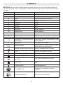
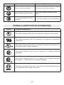
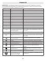
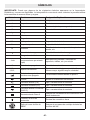
SYMBOLS
IMPORTANT: Some of the following symbols may be used on your tool. Please study them and
learn their meaning. Proper interpretation of these symbols will allow you to operate the tool better
and safer.
Symbol Name Designation/Explanation
V Volts Voltage
A Amperes Current
Hz Hertz Frequency (cycles per second)
W Watt Power
kg Kilograms Weight
min Minutes Time
s Seconds Time
Wh Watt-hours Battery capacity
Ah Ampere-hours Battery capacity
ø Diameter Size of drill bits, grinding wheels, etc.
n0No load speed Rotational speed, at no load
n Rated speed Maximum attainable speed
…/min Revolutions or reciprocations per
minute (rpm)
Revolutions, strokes, surface speed, orbits,
etc. per minute
O Off position Zero speed, zero torque...
1,2,3,…
Ⅰ,Ⅱ,Ⅲ, Selector settings Speed, torque, or position settings. Higher
number means greater speed
Innitely variable selector with off Speed is increasing from 0 setting
Arrow Action in the direction of arrow
Alternating current (AC) Type or a characteristic of current
Direct current (DC) Type or a characteristic of current
Alternating or direct current
(AC / DC) Type or a characteristic of current
Class II tool Designates Double Insulated Construction
tools.
Protective earth Grounding terminal
Li-ion RBRC seal Designates Li-ion battery recycling
program
Read the instructions Alerts user to read manual

-9-
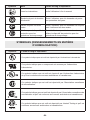
Symbol Name Designation/Explanation
Wear eye protection symbol Alerts user to wear eye protection
Always operate with two hands Alerts user to always operate with two
hands
Do not use the guard for cut-off
operations Do not use the guard for cut-off operations
SYMBOLS (CERTIFICATION INFORMATION)
Symbol Designation/Explanation
This symbol designates that this tool is listed by Underwriters Laboratories.
This symbol designates that this component is recognized by Underwriters
Laboratories.
This symbol designates that this tool is listed by Underwriters Laboratories, to
United States and Canadian Standards.
This symbol designates that this tool is listed by the Canadian Standards
Association.
This symbol designates that this tool is listed by the Canadian Standards
Association, to United States and Canadian Standards.
This symbol designates that this tool is listed by the Intertek Testing Services,
to United States and Canadian Standards.

-10-
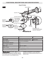
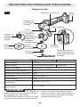
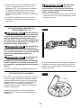
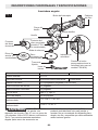
FUNCTIONAL DESCRIPTIONS AND SPECIFICATIONS
Angle Grinder
Fig. 1
Spindle Lock
Switch Button
Speed
Indicator
Cut-off
Wheel (not
Supplied)
Grinding
Wheel (not
Supplied)
Lock Nut
Wrench
Backing Flange
Cut-off Wheel
Guard (Model
FT311, Not
Supplied)
Grinding
Wheel
Guard
Press Button for
Preselecting the Speed
(Only for FX3181A)
Spindle
Auxiliary Handle
Filter
Cover
Model No. FX3181A FX3181
Rated Voltage 24 V d.c.
Rated Speed 3500/5000/7000/10000 RPM 10000 RPM
Wheel Diameter 4-1/2"/5" (115/125mm)
Grinding Wheel Thickness 1/4"
Cut-off Wheel Thickness 1/8"
Wheel Type Type 27 & Type 41
Spindle Thread 5/8''
Recommended operating temperature -4 – 104°F (-20 – 40℃)
Recommended storage temperature < 122℉ (< 50℃)
WARNING Use ONLY Type 27
depressed-center grinding
wheels with 1/4" thickness. Use ONLY Type 41
cut-off wheels with this angle grinder tool (such
as the accessories not provided with this
product). This product is only designed for
grinding and cutting-off. Use for any other
purpose is not recommended and may result in
serious injury.

-11-
ASSEMBLY
WARNING Detach the battery pack
from the tool before
making any assembly, adjustments or
changing accessories. Such preventive safety
measures reduce the risk of starting the tool
accidentally.
WARNING To reduce the risk of
injury, always remove the
battery pack before making any adjustments
or changing accessories.
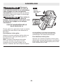
TO ATTACH/DETACH BATTERY PACK (FIG. 2)
Be careful not to turn on the tool when attaching
the battery pack.
To attach the battery pack:
Align the raised rib on the battery pack with the
grooves in the tool, and then slide the battery
pack onto the tool.
NOTICE: When placing the battery pack
onto the tool, be sure that the raised rib
on the battery pack aligns with the groove
inside the tool and that the latches snap into
place properly. Improper attachment of the
battery pack can cause damage to internal
components.
To detach the battery pack:
Depress the battery-release button located
on the front of the battery pack to release the
battery pack. Pull the battery pack out and
remove it from the tool.
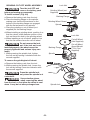
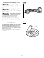
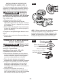
WHEEL GUARD INSTALLATION (FIG. 3)
This tool is shipped with two guards. A guard
must be used when using the tool as a grinder
or cut-off tool.
WARNING Keep the guard between
you and the wheel. Do not
direct the guard opening toward your body.
a. Remove the battery pack from the tool.
b. Align the three raised ribs on the guard with
the three notches on the collar. Place the
guard onto the collar (1).
c. Turn the guard clockwise to the desired
position (2).
Rotation is possible in one direction, only!
d. Remove in reverse order.
NOTICE: Use only grinding wheels of the
specied size with the grinding guard. Use
only cut-off wheels of the specied size with
the cutting guard.
1
2
Fig. 3
Fig. 2
Battery-release
Button

-12-
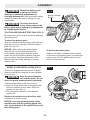
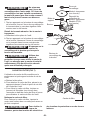
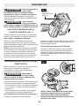
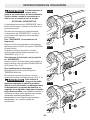
GRINDING /CUT-OFF WHEEL ASSEMBLY
WARNING Turn the tool OFF and
remove the battery pack
before performing any assembly.
To install a wheel: (Fig. 4-6)
a. Remove the battery pack from the tool.
b. Place the backing ange on the spindle,
making sure that the at surfaces on the
bottom of the backing ange are engaged
with the at surfaces on the spindle.
c. Place the grinding or cut-off wheel (not
supplied) on the backing ange.
d. When installing a grinding wheel, position it so
that the raised, small diameter portion of the
lock nut faces the hole in the grinding wheel.
e. When installing a cut-off wheel, position it so
that the at surface faces the cut-off wheel
WARNING Do not reverse the lock
nut. If the lock nut is not
installed properly, the wheel cannot be
properly tightened and serious injury can
result.
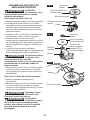
f. While pressing the spindle lock, tighten
the lock nut by turning it clockwise with the
wrench supplied.
To remove the grinding/cut-off wheel:
a. Remove the battery pack from the tool.
b. While pressing the spindle lock, loosen the
lock nut by turning it counter-clockwise with
the wrench supplied.
WARNING Press the spindle lock
only when the spindle is at
a standstill.
WARNING Use protective gloves
when removing the wheel
from the tool, or rst allow the wheel to cool
down. It may be hot after prolonged use.
Fig. 6
Spindle lock
Fig. 4 Lock Nut
Backing Flange
Grinding Wheel (not
Supplied)
Grinding Wheel Guard
Spindle
Fig. 5 Lock Nut
Backing Flange
Spindle
Cut-off Wheel
(Not Supplied)
Cut-off Wheel
Guard (Model
FT311, Not
Supplied)

-13-
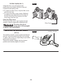
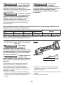
FILTER COVER (FIG. 7)
Using the lter cover will improve the
performance and extend the life of the tool.
a. Remove the battery pack.
b. To attach the lter cover, snap the lter cover
onto the tool foot.
c. To remove the lter cover, insert a athead
screwdriver (not supplied) into the notch at
the top of the lter cover and pry the lter
cover away from the tool.
Clean the Filter cover
To clean the lter cover, tap it against a hard
surface or blow it clean with compressed air.
WARNING To reduce the risk of
injury, wear safety goggles
or glasses with side shields.
INSTALLING THE AUXILIARY HANDLE
(FIG. 8)
The auxiliary handle, used to guide and balance
the tool, can be threaded into the front housing
on either side of the tool, depending on personal
preference and comfort.
Thread the auxiliary handle into the desired
position and securely tighten it in place.
Fig. 8 Auxiliary Handle
Fig. 7
Filter Cover

-14-
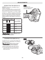
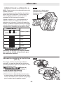
ADJUSTMENTS
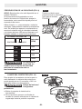
PRESELECTING THE SPEED (FIG. 9)
NOTICE: This function is available only on
model of FX3181A.
Your tool is equipped with a memory function.
After turning the tool off, the tool will revert to
the previous setting when it is turned on again.
Use the + or - button to increase or decrease
the speed. Each press changes the speed one
level. The table below shows the relationship
between rotational speed and the number of
LEDs that shine in the indicator on the foot of
the tool.
The Number of LEDs
Speed (RPM)
ON OFF
3500
5000
7000
10000
WARNING Never change speed
setting while the tool is
running for safety reasons.
ADJUSTING THE GUARD (FIG. 10)
To adjust the tool to suit the task at hand, the
guard hood can be adjusted by 12 notches or
360° without a tool.
WARNING Risk of injury! Wear
protective gloves.
a. Remove the battery pack from the tool.
b. Turn guard opposite to the direction-of-
rotation arrow on the gear head to the
required position.
X
click
click
click
Fig. 10
Fig. 9
Press Button for
Preselecting the Speed
(Only for FX3181A)

-15-
OPERATION INSTRUCTIONS
WARNING Battery tools are always in
operating condition. Be
careful when the tool is not in use or when
carrying it at your side.
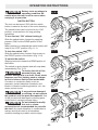
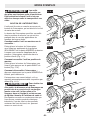
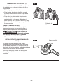
SWITCH BUTTON
The tool can be turned “ON” with the switch
button, located at the side of the motor housing.
The switch button can be locked in the “ON”
position, a convenience for long grinding
operations.
To turn the tool “ON” without locking it:
Slide the switch button forward by applying
pressure ONLY at the REAR portion of the
button.
When pressure is released the switch button will
snap to the “OFF” position (Fig. 11-1).
To lock the switch “ON”:
Slide the switch button forward, then press on
the FRONT portion of the button (Fig. 11-2).
To unlock the switch:
Simply press and release the REAR portion of
the button.
The switch is spring loaded and will snap back
automatically (Fig. 11-3).
WARNING To reduce the risk of re,
personal injury, and
product damage due to a short circuit, never
immerse your tool, battery pack or charger
in uid or allow a uid to ow inside them.
Corrosive or conductive uids, such as
seawater, certain industrial chemicals, and
bleach or bleach-containing products, etc. can
cause a short circuit.
WARNING If any parts are damaged
or missing, do not operate
this product until the parts are replaced. Use
of this product with damaged or missing parts
could result in serious personal injury.
WARNING Do not attempt to modify
this tool or create
accessories not recommended for use with
this tool. Any such alteration or modication is
misuse and could result in a hazardous
condition leading to possible serious injury.
Fig. 11-1
a
b
Fig. 11-2
a
b
Fig. 11-3

-16-
WARNING To prevent accidental
starting that could cause
serious personal injury, always remove the
battery pack from the tool when assembling
parts, making adjustments, or cleaning the
tool.
This cordless angle grinder must be used
only with the battery packs and chargers
listed below:
Battery Pack Charger
2.5Ah 5Ah 8Ah 12Ah
FLEX FX0111 FLEX FX0121 FLEX FX0221 FLEX FX0231 FLEX FX0411 FLEX FX0421
NOTICE: Please refer to the battery pack and charger manuals for detailed operating
information.
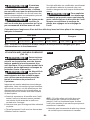
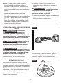
USING WITH GRINDING WHEEL (FIG. 12)
WARNING Always wear safety
goggles or safety glasses
with side shields during power tool
operation. If the operation is dusty, also
wear a dust mask.
WARNING A grinding guard must be
installed when using a
grindig wheel to provide maximum
protection for the operator.
Check the grinding wheels before application.
Discard wheels that have been dropped,
bumped, subjected to extreme changes in
temperature, or have come into contact with
solvents or liquids.
a. Before beginning a period of work, test the
tool by letting it spin for one minute before
applying it to the workpiece.
b. Make sure that the workpiece is rmly
clamped in place.
c. Hold the tool securely with both hands.
d. Start the tool.
NOTICE: If the battery is inserted when the tool
switch is in the “ON” position, the tool will not run.
Turn the tool off, then back on to begin work.
e. Allow the accessory to reach full speed before
beginning work.
f. For a uniform nish, hold the tool at an angle
of approximately 10° to 15° and apply (Fig.12)
constant pressure. Too great an angle causes
concentrated pressure on small areas, which
may gouge or burn the work surface.
g. Control the pressure and surface contact
between accessory and workpiece.
WARNING Do not apply too much
pressure. Too much
pressure will cause the tool to overload and
may cause personal injury.
h. When nished, turn off the tool and make sure
that it comes to a complete stop before laying
it down.
10°~ 15°
Fig. 12

-17-
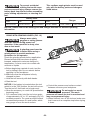
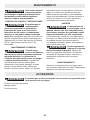
USING WITH CUT-OFF WHEEL (FIG. 13)
WARNING Always wear safety
goggles or safety glasses
with side shields during power tool
operation. If operation is dusty, also wear a
dust mask.
WARNING A cut-off guard must be
installed when using a
cut-off wheel to provide maximum protection
for the operator.
WARNING Using the cut-off wheel in
a grinding operation will
cause the wheel to crack and break,
resulting in serious personal injury.
The cut-off wheel is suited for small cut-off
operations only. When using a cut-off wheel,
hold the tool as shown and use only the edge of
the wheel.
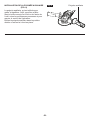
DUST EXTRACTION
To reduce exposure to silica dust when surface-
grinding concrete, use this grinder with FLEX
Surface Grinding Dust Shroud model FT312
connected to a suitable dust extractor / vacuum
(both sold separately).
Refer to the manual for FLEX FT312 for more
information.
Fig. 13
Fig. 14
FT312

-18-
MAINTENANCE
WARNING To avoid serious personal
injury, always remove the
battery pack from the tool when cleaning or
performing any maintenance.
SERVICE
WARNING Preventive maintenance
performed by
unauthorized personnel may result in
misplacing of internal wires and
components which could cause a serious
hazard. We recommend that all tool service be
performed by a FLEX Factory Service Center or
Authorized FLEX Service Station.
GENERAL MAINTENANCE
WARNING When servicing, use only
identical replacement
parts. Use of any other parts could create a
hazard or cause product damage. Periodically
inspect the entire product for damaged, missing,
or loose parts such as screws, nuts, bolts, caps,
etc. Tighten securely all fasteners and caps and
do not operate this product until all missing or
damaged parts are replaced. Please contact
customer service or an authorized service
center for assistance.
CLEANING
WARNING The tool may be cleaned
most effectively with
compressed dry air. Always wear safety
goggles when cleaning tools with
compressed air. Ventilation openings and
switch levers must be kept clean and free of
foreign matter. Do not attempt to clean by
inserting pointed objects through openings.
WARNING Certain cleaning agents
and solvents damage
plastic parts. Some of these are: gasoline,
carbon tetrachloride, chlorinated cleaning
solvents, ammonia and household detergents
that contain ammonia.
STORAGE
Store the tool indoors in a place that is
inaccessible to children. Keep away from
corrosive agents.
ACCESSORIES
WARNING The use of any other accessories not specied in this manual may create a
hazard.
Grinding Wheel Guard
Auxiliary Handle
Wrench

-19-
FLEX 5 YEAR LIMITED WARRANTY
Chervon North America, Inc. ("Seller") warrants to the original purchaser only, that all FLEX 24V
products will be free from defects in material or workmanship for a period of ve years from date of
purchase when the original purchaser registers the product within 30 days from the date of original
retail purchase and retains their receipt as proof of purchase. THE 5-YEAR LIMITED WARRANTY
PERIOD IS CONDITIONED ON REGISTRATION OF THE PRODUCT WITHIN 30 DAYS OF
PURCHASE AND ONLY APPLICABLE TO FLEX 24V TOOLS, BATTERIES AND CHARGERS. If the
original purchaser does not register their product within 30 days, the foregoing limited warranty will
apply for a duration of three years. Product registration can be completed online at
www.registermyex.com.
24V Tools: 5-Year Limited Warranty with Registration
24V Batteries and Chargers: 5-Year Limited Warranty with Registration
Corded, 12V and 20V FLEX Legacy Products: 1-Year Limited Warranty, No Registration Benet
Accessories and Attachments: No Warranty
SELLER’S SOLE OBLIGATION AND YOUR EXCLUSIVE REMEDY under this 5-Year Limited
Warranty and, to the extent permitted by law, any warranty or condition implied by law, shall be
the repair or replacement of parts, without charge, which are defective in material or workmanship
and which have not been misused, carelessly handled, or repaired by persons other than a FLEX
Authorized Service Dealer. This warranty does not cover part failure due to normal wear and tear.
To make a claim under warranty, return the complete product, transportation prepaid, to any FLEX
Authorized Service Dealer. For Authorized FLEX Service Dealers, please visit www.registermyex.com
or call 1-833-FLEX-496 (1-833-353-9496).
This 5-Year Limited Warranty does not apply to accessories, attachments or parts.
Any implied warranties applicable to a product shall be limited in duration equal to the duration of the
express warranties applicable to such product, as set forth in the rst paragraph above. Some states
in the U.S. and some Canadian provinces do not allow limitations on how long an implied warranty
lasts, so the above limitation may not apply.
FLEX is not responsible for direct, indirect, incidental or consequential damages. Some U.S. states
and Canadian provinces do not allow limitations on how long an implied warranty lasts and/or do
not allow the exclusion or limitation of incidental or consequential damages, so the above limitations
or exclusions may not apply. This limited warranty gives you specic legal rights, and you may also
have other rights which vary by state in the U.S. and by province in Canada.
This limited warranty applies only to products sold within the United States of America, Canada and
the commonwealth of Puerto Rico. For warranty coverage within other countries, contact your local
FLEX dealer.
© Chervon North America, 1203 E. Warrenville Rd., Naperville, IL 60563
www.expowertools.com
www.registermyex.com
1-833-FLEX-496 (1-833-353-9496)

-20-
SYMBOLES RELATIFS À LA SÉCURITÉ
La raison d’être des symboles relatifs à la sécurité est d’attirer votre attention sur des dangers
possibles. Il est important de vous familiariser avec les symboles relatifs à la sécurité et les
explications qui les accompagnent an de bien les comprendre. Les avertissements et les symboles
associés ne sufsent pas à éliminer tous les dangers. Les instructions et les avertissements qu’ils
donnent ne sauraient remplacer des mesures de prévention des accidents appropriées.
AVERTISSEMENT Lisez toutes les consignes de sécurité qui sont contenue dans ce
Mode d’emploi, y compris tous les symboles d’alerte relatifs à la
sécurité tels que « DANGER », « AVERTISSEMENT » et « MISE EN GARDE », et assurez-vous
que vous les comprenez bien avant de commencer à utiliser cet outil. La non-observation de toutes
les instructions gurant ci-après pourrait causer un choc électrique, un incendie et/ou des blessures
personnelles graves.
Les dénitions ci-dessous décrivent le niveau de gravité pour chaque terme signalant un danger.
Veuillez lire le mode d’emploi et lire la signication de ces symboles.
C’est le symbole d’alerte relatif à la sécurité. Il est utilisé pour vous
avertir de l’existence possible d’un danger de lésion corporelle.
Obéissez à tous les messages relatifs à la sécurité qui suivent ce
symbole pour éviter tout risque de blessure ou même de mort.
DANGER DANGER indique une situation dangereuse qui, si elle n’est pas
évitée, causera la mort d’une personne ou une blessure grave.
AVERTISSEMENT AVERTISSEMENT indique une situation dangereuse qui, si elle
n’est pas évitée, causera la mort d’une personne ou une blessure
grave.
MISE EN GARDE MISE EN GARDE, conjointement avec le symbole d’alerte en
liaison avec la sécurité, indique une situation dangereuse qui, si
elle n'est pas évitée, causera une blessure légère ou modérée.
Messages d’information et de prévention des dommages
Ils informent l’utilisateur d’informations et/ou d’instructions importantes qui pourraient entraîner des
dommages matériels ou aux équipements s’ils ne sont pas suivis. Chaque message est précédé par
le terme « AVIS », comme dans l’exemple ci-dessous :
AVIS : Un dommage matériel et/ou aux équipements peut survenir si ces instructions ne sont pas
suivies.
AVERTISSEMENT Pendant leur fonctionnement, les outils
électriques peuvent projeter des corps
étrangers dans les yeux de leur utilisateur et lui iniger de graves blessures
aux yeux. Portez toujours des lunettes de protection ou des lunettes de
sécurité à écrans latéraux et un masque couvrant tout le visage lors de
l’utilisation de ce produit. Nous recommandons de porter un masque de
sécurité à vision latérale large au-dessus des lunettes ordinaires ou des
lunettes de sécurité standard avec des écrans de protection sur les côtés.
Utilisez toujours un équipement de protection des yeux indiquant qu’il est
conforme à la norme ANSI Z87.1.
La page est en cours de chargement...
La page est en cours de chargement...
La page est en cours de chargement...
La page est en cours de chargement...
La page est en cours de chargement...
La page est en cours de chargement...
La page est en cours de chargement...
La page est en cours de chargement...
La page est en cours de chargement...
La page est en cours de chargement...
La page est en cours de chargement...
La page est en cours de chargement...
La page est en cours de chargement...
La page est en cours de chargement...
La page est en cours de chargement...
La page est en cours de chargement...
La page est en cours de chargement...
La page est en cours de chargement...
La page est en cours de chargement...
La page est en cours de chargement...
La page est en cours de chargement...
La page est en cours de chargement...
La page est en cours de chargement...
La page est en cours de chargement...
La page est en cours de chargement...
La page est en cours de chargement...
La page est en cours de chargement...
La page est en cours de chargement...
La page est en cours de chargement...
La page est en cours de chargement...
La page est en cours de chargement...
La page est en cours de chargement...
La page est en cours de chargement...
La page est en cours de chargement...
La page est en cours de chargement...
La page est en cours de chargement...
La page est en cours de chargement...
La page est en cours de chargement...
La page est en cours de chargement...
La page est en cours de chargement...
-
 1
1
-
 2
2
-
 3
3
-
 4
4
-
 5
5
-
 6
6
-
 7
7
-
 8
8
-
 9
9
-
 10
10
-
 11
11
-
 12
12
-
 13
13
-
 14
14
-
 15
15
-
 16
16
-
 17
17
-
 18
18
-
 19
19
-
 20
20
-
 21
21
-
 22
22
-
 23
23
-
 24
24
-
 25
25
-
 26
26
-
 27
27
-
 28
28
-
 29
29
-
 30
30
-
 31
31
-
 32
32
-
 33
33
-
 34
34
-
 35
35
-
 36
36
-
 37
37
-
 38
38
-
 39
39
-
 40
40
-
 41
41
-
 42
42
-
 43
43
-
 44
44
-
 45
45
-
 46
46
-
 47
47
-
 48
48
-
 49
49
-
 50
50
-
 51
51
-
 52
52
-
 53
53
-
 54
54
-
 55
55
-
 56
56
-
 57
57
-
 58
58
-
 59
59
-
 60
60


Flex FX3181 Manuel utilisateur
- Catégorie
- Outils électroportatifs
- Taper
- Manuel utilisateur
dans d''autres langues
- English: Flex FX3181 User manual
- español: Flex FX3181 Manual de usuario

