Let's Go Aero 429756 Guide d'installation
- Taper
- Guide d'installation

lippertcomponents.com 574-537-8900 Rev: 02.17 - Jack-It
®
Jack-It
®
Installation and Owner’s Manual
(For Aftermarket Application)
Table of Contents
Introduction ............................................ 1
Safety Requirements ................................... 1
Resources Required ................................... 2
Installation Instructions ............................... 2
Manual Jack Operation ................................ 3
Securing Bikes ......................................... 4
Dimensions Of Assembled Jack-It ..................... 4
Maximum Weight Capacity ............................ 4
Jack-It
®
Installation and
Owner’s Manual
(For Aftermarket Applications)
Introduction
The Jack-It
®
is a bicycle rack designed to attach to
your RV.
Additional information about this product can be obtained
from www.lci1.com/support or by downloading the free
myLCI app. The app is available on iTunes
®
for iPhone
®
and iPad
®
and also on Google Play
™
for Android
™
users.
iTunes, iPhone, and iPad are registered trademarks of
Apple Inc. Google Play and Android are trademarks of
Google Inc.
Lippert Components, Inc. recommends that the following
inspections, troubleshooting, component replacement and
verications be completed only by certied RV technicians.
Safety Requirements
Patent protected, trademarked, and produced by Let’s Go Aero, Inc.
Corporate Ofce: 4474 Barnes Road, Colorado Springs, CO 80917 USA.
Made in Taiwan.
US Patent Numbers: 8,899,456, D717,716, D717,717, D684,917, D722,289,
patents pending.
MOVING PARTS CAN PINCH, CRUSH OR CUT. KEEP
CLEAR AND USE CAUTION.
FAILURE TO FOLLOW THE INSTRUCTIONS PROVIDED
IN THIS MANUAL MAY RESULT IN DEATH, SERIOUS
INJURY, VEHICLE DAMAGE OR VOIDING OF THE
COMPONENT WARRANTY.
THE USE OF THIS PRODUCT WHILE BICYCLES ARE
LOADED MAY AFFECT THE TURNING RADIUS ON
SOME VEHICLES. CHECK THE TURNING RADIUS
BEFORE TRAVEL.
1

lippertcomponents.com 574-537-8900 Rev: 02.17 - Jack-It
®
Jack-It
®
Installation and Owner’s Manual
(For Aftermarket Application)
Resources Required
Installation Instructions
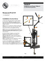
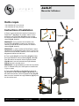
1. Remove the tongue jack from the coupler. Position
the PowerTower™ (Fig.1G) on the coupler. Place the
tongue jack on the PowerTower (Fig.1G) and secure
both to the coupler using 3 nuts, bolts and washers each
(Fig.1H, 1I and 1J).
NOTE: If there is no tongue jack, attach the PowerTower
(Fig.1G) to the coupler on the front of the trailer using 3
nuts, bolts and washers each (Fig.1H, 1I and 1J).
NOTE: There are two PowerTower options available. The
standard option has an inside clearance of 22 ½”. The mini
jack, to accommodate manual tongue jacks, has an 18 ½”
inside clearance.
2. Attach the Stinger™ (Fig.1F) to the PowerTower
(Fig.1G) using the NoMotion™ pin and washers
(Fig. 1A, 1C and 1D). For safety, insert the cotter pin
(Fig.1B) through the hole at the end of the NoMotion pin
(Fig.1A) after tightening securely.
NOTE: The NoMotion pins are lockable with a customer-
supplied padlock having a ¼” or smaller hasp.
3. Attach the base (Fig.1E) to Stinger (Fig.1F) using the
NoMotion pin and washers (Fig.1A, 1C and 1D). For
safety, insert the cotter pin (Fig.1B) through the hole at the
end of the NoMotion pin (Fig.1C) after tightening securely.
Fig.1
• ⁄” Socket Wrench
• ¾” Socket Wrench
2
A
B
C
D
E
F
G
H
I
J

lippertcomponents.com 574-537-8900 Rev: 02.17 - Jack-It
®
Jack-It
®
Installation and Owner’s Manual
(For Aftermarket Application)
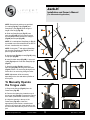
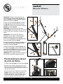
Fig.2
NOTE: Several hole positions are provided
for cradles (Fig.2A). Pads (Fig.2D) and
SwayStop™ pins (Fig.2F) slide along the
length of the wings (Fig.2G).
4. Slide one SwayStop pin (Fig.2F) onto
each wing (Fig.2G) from the bottom so that
the SwayStop locates between the snap pin
(Fig.2H) and the pad (Fig.2D).
NOTE: A 2
nd
and optional SwayStop pin (Fig.3)
is provided to secure both wheels of the bike to
the rack. Install at this time if desired.
NOTE: If using the 2
nd
and optional SwayStop
pin, then the SwayStop pins (Fig.2F) should
point in opposite directions.
5. Attach wings (Fig.2G) to base (Fig.2E) using
2 snap pins (Fig.2H).
6. Install 6 rubber straps (Fig.2B): 1 onto each
cradle (Fig.2A) and 1 onto each SwayStop pin
(Fig.2F).
7. Attach 4 cradles (Fig.2A). Attach 2 to
each wing (Fig.2G), securing with cotter pins
(Fig.2C). Attach 1 on each wing facing the tow
vehicle and 1 on each wing facing the trailer.
NOTE: Adjustment will be necessary
depending on the size and desired position of
the bicycles.
3
Fig.3
A
A
D
D
F
H
G
B
B
C
To Manually Operate
the Tongue Jack
1. Remove the Stinger (Fig.4A) from the
PowerTower (Fig.4B).
2. Remove the rubber plug located on top of
the tongue jack (Fig.5A) to expose the manual
drive shaft. (PowerTower removed for clarity.)
3. Utilize the opening in the top of the
PowerTower (Fig.6A) to insert the
appropriately-sized ratchet, extension and
socket or the tongue jack crank handle to turn
the drive shaft and manually raise or lower the
jack.
Fig.4
Fig.5
Fig.6
G
E
G
A
B
A
A

lippertcomponents.com 574-537-8900 Rev: 02.17 - Jack-It
®
Jack-It
®
Installation and Owner’s Manual
(For Aftermarket Application)
Manual information may be distributed as a complete
document only, unless Lippert Components provides
explicit consent to distribute individual parts.
All manual information is subject to change without
notice. Revised editions will be available for free
download at www.lippertcomponents.com. Manual
information is considered factual until made obsolete by
a revised version.
Please recycle all obsolete materials and contact
Lippert Components with concerns or questions.
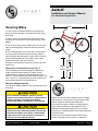
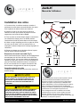
Securing Bikes
1. For 2 bicycles, the best technique is to position the
bicycles front to back/back to front with the chain ring to
the outside.
2. Hang 1 bicycle on the trailer side of the bicycle rack
so the top of the wheels are each supported by a cradle
(Fig.7).
3. Secure by tensioning each rubber strap over the top of
each tire and engaging a strap hole with the end of the
cradle.
4. Use 1 SwayStop pin to secure at least 1 wheel below
the frame where the wheel crosses the wing using the
same technique with the stop pin rubber strap. A second
and optional SwayStop pin is provided to secure both
wheels of the bike to the rack if desired.
5. Repeat for a 2nd bicycle on the tow vehicle side of the
bicycle rack.
ALWAYS MAKE SURE ALL CONNECTIONS BETWEEN
THE BICYCLE RACK AND THE TRAILER COUPLER ARE
SECURE/TIGHT/READY FOR TRAVEL. ALWAYS MAKE
SURE THE BICYCLES ARE SECURELY ATTACHED TO
THE BICYCLE RACK BEFORE DRIVING.
4
Fig.7
46 ¾”
60 3/8”
56 3/8”
or
Maximum Weight Capacity
The maximum weight capacity of the Jack-It bicycle rack is
80 pounds.
DO NOT EXCEED THE WEIGHT CAPACITY OR THE
RECEIVER HITCH MANUFACTURER’S TONGUE WEIGHT
RATING. FAILURE TO ACKNOWLEDGE WEIGHT
RATINGS MAY RESULT IN DAMAGE TO THE TRAILER.
29 3/16”
22 ½”
18 ½”
or
or
25 3/16”
Dimensions of Assembled Jack-It (Fig. 7)
Check dimensions to ensure adequate clearances for
tongue jacks and liquid propane (LP) tanks. Critical
measurements for jacks are inside clearances of 22 ½”
and 18 ½” for the standard and manual PowerTowers. The
29 ⁄” and 25 ⁄” measurements from the coupler to the
wing base will determine LP tank clearance.

lippertcomponents.com 574-537-8900 Rev: 02.17 - Jack-It
®
Jack-It
®
Installation and Owner’s Manual
(For Aftermarket Application)
Table des matières
Introduction ............................................ 1
Consignes de sécurité ................................. 1
Outils requis ............................................ 2
Instructions d’installation ............................. 2
Installation des vélos .................................. 4
Jack-It
®
Manuel de l’utilisateur
Introduction
Le Jack-IT
®
est un porte-vélos conçu pour être xé à votre
VR.
Vous pouvez obtenir des renseignements supplémentaires
concernant ce produit sur le site www.lci1.com/support ou
en téléchargeant l’application gratuite myLCI. L’application
est offerte sur iTunes
®
pour iPhone
®
et iPad
®
et aussi sur
Google Play
MC
pour les utilisateurs d’Android
MC
.
iTunes, iPhone et iPad sont des marques de commerce
déposées d’Apple, inc. Google Play et Android sont des
marques de commerce de Google, inc.
Lippert Components, inc. recommande que les travaux
d’inspection, de dépannage, de remplacement de
composants et de vérication soient effectués par des
techniciens en VR certiés.
Consignes de sécurité
SE TENIR ÉLOIGNÉ DES PIÈCES MOBILES QUI
PEUVENT PINCER, ÉCRASER OU COUPER. FAIRE
PREUVE DE PRUDENCE.
LE NON-RESPECT DES CONSIGNES FOURNIES DANS
LE PRÉSENT MANUEL PEUT ENTRAÎNER LA MORT, DE
GRAVES BLESSURES, DES DOMMAGES AU VÉHICULE
OU L’ANNULATION DE LA GARANTIE SUR LES PIÈCES.
L’UTILISATION DE CE PRODUIT PENDANT QUE LES
VÉLOS SONT FIXÉS EN PLACE PEUT AVOIR UNE
INCIDENCE SUR LES RAYONS DE VIRAGE DE CERTAINS
VÉHICULES. VÉRIFIER LES RAYONS DE VIRAGE AVANT
LES DÉPLACEMENTS.
1
Protégé par brevet, marque de commerce et produit par Let’s Go Aero, inc.
Siège social: 4474 Barnes Road, Colorado Springs, CO 80917 É.-U.
Fabriqué à Taïwan.
Numéros de brevets américains: 8,899,456, D717,716, D717,717, D684,917,
D722,289, en instance de brevet.

lippertcomponents.com 574-537-8900 Rev: 02.17 -Jack-It
®
Jack-It
®
Manuel de l’utilisateur
Outils requis
• Clé à douilles de ⁄ po (14 mm)
• Clé à douilles de ¾ po (19 mm)
2
Instructions d’installation
1. Retirer le vérin de èche du coupleur. Positionner le
PowerTower
MC
(Fig.1G) sur le coupleur. Placer le vérin
de èche sur le PowerTower (Fig.1G) et xer les deux
au coupleur à l’aide de trois écrous, boulons et rondelles
chacun (Fig.1H, 1I et 1J).
REMARQUE: S’il n’y a pas de vérin de èche, xer
le PowerTower (Fig.1G) au coupleur sur l’avant de la
caravane à l’aide de trois écrous, boulons et rondelles
chacun (Fig.1H, 1I et 1J).
REMARQUE: Il y a deux options de PowerTower. L’option
standard offre un dégagement intérieur de 571,5 mm. Pour
recevoir les vérins de fléche manuels, le mini vérin offre un
dégagement intérieur de 469,9 mm.
2. Fixer le guide (Fig.1F) au PowerTower (Fig.1G) à l’aide
de la tige NoMotion
MC
et des rondelles (Fig.1A, 1C et 1D).
Pour des raisons de sécurité, insérer la goupille fendue
(Fig.1B) dans le trou de l’extrémité de la tige NoMotion
(Fig.1A) une fois le tout bien serré.
REMARQUE: Les tiges NoMotion peuvent être verrouillées
avec un cadenas fourni par le client ayant un moraillon de
1/4 po ou moins.
3. Fixer la base (Fig.1E) au guide (Fig.1F) à l’aide de la
tige NoMotion et des rondelles (Fig.1C, 1D and 1A). Pour
des raisons de sécurité, insérer la goupille fendue (Fig.1B)
dans le trou de l’extrémité de la tige NoMotion (Fig.1C) une
fois le tout bien serré.
Fig.1
A
B
C
D
E
F
G
H
I
J

lippertcomponents.com 574-537-8900 Rev: 02.17 -Jack-It
®
Jack-It
®
Manuel de l’utilisateur
3
REMARQUE: Plusieurs positions de trous sont
fournies pour les brides de xation (Fig.2A). Les
tampons (Fig.2D) et les tiges SwayStop
MC
(Fig.2F)
glissent le long des ailes (Fig.2G).
4. Glisser une tige SwayStop (Fig.2F) sur chaque
aile (Fig.2G) à partir du bas de sorte que la tige
SwayStop se positionne entre la goupille à pression
(Fig.2H) et le tampon (Fig.2D).
REMARQUE: Une deuxième tige optionnelle
SwayStop (Fig.3) est fournie pour xer les deux roues
du vélo au porte-vélos; l’installer à cette étape-ci, au
besoin.
REMARQUE: Si la deuxième tige optionnelle
SwayStop
n’est pas utilisée, les tiges SwayStop
(Fig.2F) devraient pointer en sens opposés.
5. Fixer les ailes (Fig.2G) à la base (Fig.2E) à l’aide
de deux goupilles à pression (Fig.2H).
6. Installer six sangles en caoutchouc (Fig.2B): une
sur chaque bride de xation (Fig.2A) et une sur
chaque tige SwayStop (Fig.2F).
7. Attacher quatre brides de xation (Fig.2A), deux
sur chaque aile (Fig.2G), en xant en place avec les
goupilles fendues (Fig.2C). En xer une sur chaque
aile orientée vers le véhicule remorqueur et une sur
chaque aile orientée vers la caravane.
REMARQUE: Des réglages peuvent être nécessaires
selon la taille et la position souhaitée des vélos.
Fig.2
A
A
D
F
H
G
B
B
C
Fig.3
A
B
D
G
E
G
Fonctionnement manuel
du vérin de èche
1. Retirer le guide (Fig.4A) du PowerTower (Fig.4B).
2. Retirer le bouchon en caoutchouc situé sur le
dessus du vérin de èche (Fig.5A) pour exposer
l’arbre d’entraînement manuel (le PowerTower a été
retiré aux fins de clarté).
3. Dans l’ouverture sur le dessus du PowerTower
(Fig.6A), insérer la clé à cliquet, l’extension et
la douille appropriées ou la manivelle du vérin
de èche pour tourner l’arbre d’entraînement et
soulever ou abaisser manuellement le vérin.
A
A
Fig.4
Fig.5
Fig.6

lippertcomponents.com 574-537-8900 Rev: 02.17 - Jack-It
®
Jack-It
®
Manuel de l’utilisateur
Les renseignements contenus dans le présent manuel
peuvent seulement être distribués sous forme de
document complet, à moins de recevoir l’approbation
explicite de Lippert Components pour distribuer des
parties individuelles. Tous les renseignements contenus
dans le présent manuel peuvent être modiés sans
préavis. Les éditions révisées pourront être téléchargées
gratuitement sur le site lippertcomponents.com.
Ces renseignements sont considérés comme étant
factuels jusqu’à ce qu’une version révisée les rende
désuets. Veuillez recycler tout le matériel désuet et
communiquer avec Lippert Components si vous avez des
questions ou des préoccupations.
Jack-It
®
Manuel de l’utilisateur
Installation des vélos
1. Pour deux vélos, la meilleure technique consiste à
positionner les vélos avant vers arrière/arrière vers avant
avec le plateau de chaîne orienté vers l’extérieur.
2. Installer un vélo sur le porte-vélos du côté de la
caravane de sorte que le dessus de chaque roue soit
supporté par une bride de xation (Fig.4).
3. Fixer en place en serrant chaque sangle en caoutchouc
sur le dessus de chaque pneu et en faisant pénétrer
l’extrémité de la bride de xation dans un trou de sangle.
4. Utiliser une tige SwayStop pour xer en place au moins
une roue sous le cadre, où la roue traverse l’aile, en
employant la même technique avec la sangle à goupille en
caoutchouc.
5. Répéter ces étapes pour le deuxième vélo sur le porte-
vélos du côté du véhicule remorqueur.
4
Dimensions du Jack-It assemblé (Fig.7)
Vérier les dimensions pour s’assurer que les dégagements
sont adéquats pour les vérins de èche et les réservoirs
de propane liquide. Les mesures critiques du dégagement
intérieur pour les vérins sont de 571.5 mm et de 469.9 mm
pour les PowerTower standard et manuel. Les mesures
de 741 mm et de 640 mm du coupleur à la base de l’aile
détermineront le dégagement du réservoir de propane.
Fig.7
1188 mm
1533 mm
1432 mm
or
Capacité maximale de poids
La capacité maximale de poids du porte-vélos Jack-It est
de 80 lb (36 kg).
469.9 mm
571.5 mm
or
640 mm
741 mm
or
TOUJOURS S’ASSURER QUE LES RACCORDEMENTS
ENTRE LE PORTE-VÉLOS ET LE COUPLEUR DE LA
CARAVANE SONT BIEN FIXÉS ET SERRÉS ET PRÊTS
POUR LES DÉPLACEMENTS. TOUJOURS S’ASSURER
QUE LES VÉLOS SONT SOLIDEMENT FIXÉS AU PORTE-
VÉLOS AVANT DE PRENDRE LE VOLANT.
NE PAS DÉPASSER LA CAPACITÉ DE POIDS OU LE
POIDS NOMINAL DE FLÈCHE DU FABRICANT DE
L’ATTELAGE. LE NON-RESPECT DES CAPACITÉS
NOMINALES DE POIDS PEUT ENDOMMAGER LA
CARAVANE.
-
 1
1
-
 2
2
-
 3
3
-
 4
4
-
 5
5
-
 6
6
-
 7
7
-
 8
8


Let's Go Aero 429756 Guide d'installation
- Taper
- Guide d'installation
dans d''autres langues
Autres documents
-
Curt Manufacturing 733926 Le manuel du propriétaire
-
Lippert Components 733926 Guide d'installation
-
Lippert 689052 Mode d'emploi
-
Sonnet CRESCENDO PCI G4 Guide d'installation
-
-
Simrad Pulse Compression Radar Guide d'installation
-
Reese 66561 Manuel utilisateur
-
Thule T2 Classic 2 - 2" Manuel utilisateur
-
Saris 801 Manuel utilisateur