
ATTENTION INSTALLERS:
It is your responsibility to know this product better than your customer. This includes being able to install the product according
to strict safety guidelines and instructing the customer on how to operate and maintain the equipment for the life of the product.
Safety should always be the deciding factor when installing this product and using common sense plays an important role as
well. Pay attention to all safety warnings and any other special notes highlighted in the manual. Improper installation of the unit
or failure to follow safety warnings could result in serious injury, death, or property damage. These instructions are primarily
intended to assist qualified individuals experienced in the proper installation of this appliance. Some local codes require
licensed installation/service personnel for this type of equipment. After completing the installation, return these instructions to
the customer’s package for future reference.
WARNING:
!
DO NOT DESTROY. PLEASE READ CAREFULLY AND KEEP IN A SAFE PLACE FOR FUTURE REFERENCE.
FIRE OR EXPLOSION HAZARD
WHAT TO DO IF YOU SMELL GAS
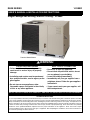
14 SEER
R8GE SERIES
Premium Model Shown
USER’S MANUAL & INSTALLATION INSTRUCTIONS

2
IMPORTANT SAFETY INFORMATION ..........................4
OPERATING INSTRUCTIONS ........................................4
Cooling Operation ........................................................4
Heating Operation ........................................................4
Turning the Air Conditioner Off ....................................4
Operating the Indoor Blower Continuously ..................4
AIR CONDITIONER MAINTENANCE .............................4
TROUbLESHOOTING ....................................................4
WARRANTY INFORMATION
A warranty certificate with full details is included with the
Air Conditioner. Carefully review these responsibilities with
your dealer or service company. The manufacturer will not
be responsible for any costs found necessary to correct
problems due to improper setup, improper installation,
adjustments, improper operating procedure on the part
of the user, etc. Some specific examples of service calls
which are not included in the limited warranty are:
• Correcting wiring problems in the electrical circuit
supplying the Air Conditioner.
• Resettingcircuitbreakersorotherswitches.
• Adjustingorcalibratingofthermostat.
USER INFORMATION

IMPORTANT SAFETY INFORMATION ..........................5
REQUIREMENTS & CODES ..........................................6
GENERAL INFORMATION .............................................7
Before You Install this Unit ...........................................7
Locating the Equipment ...............................................7
Heating Load ...............................................................7
CombustionAirRequirements ....................................7
VentingRequirements .................................................8
Circulating Air Supply ..................................................10
Air Ducts ............................................................. 10
AirFilterRequirements ....................................... 10
Unconditioned Spaces ......................................... 10
Acoustical Duct Work ........................................... 11
UNIT INSTALLATION .....................................................11
PackagingRemoval .....................................................11
Rigging&Hoisting ........................................................11
Clearances to Combustible Materials ..........................11
Ground Level ................................................................11
Rooftop .........................................................................11
Condensate Drain .......................................................11
Horizontal to Downflow Conversion .............................11
RemovalofInternalFilterRack ....................................12
InstallingFiltersintheFilterRack ................................12
RemovingFiltersfromtheFilterRack ..........................12
ELECTRICAL WIRING ....................................................
Pre - Electrical Checklist ..............................................13
Line Voltage .................................................................13
Grounding .....................................................................14
Thermostat / Low Voltage Connections .......................14
Checking Heat Anticipator Settings ...................... 15
Optional Outdoor Thermostat ............................... 15
Blower Speed ....................................................... 15
Unbalanced 3-Phase Supply Voltage ................... 15
Optional Humidistat .............................................. 16
GASSUPPLY&PIPING ...............................................16
Leak Check ..................................................................17
High Altitude Conversion..............................................17
Lp/Propane Gas Conversion .......................................17
STARTUP & ADJUSTMENTS ........................................18
Pre - Start Checklist .....................................................18
Start-up Procedure .......................................................18
Air Circulation ....................................................... 18
System Cooling .................................................... 18
System Heating .................................................... 18
Verifying&AdjustingTemperatureRise ......................18
Verifying&AdjustingFiringRate .................................19
Verifying Operation of Over-Temperature
Limit Control .................................................................19
Verifying Burner Operation ...........................................19
RefrigerantCharging ....................................................19
Manifold Pressure Adjustment .....................................20
OPERATING SEQUENCE ..............................................20
Heating Mode ...............................................................20
Cooling Mode ...............................................................21
Fan Mode .....................................................................21
EQUIPMENT MAINTENANCE ........................................21
Cleaning of Heat Exchanger ........................................22
Cleaning of Burners .....................................................22
COMPONENT FUNCTIONS ...........................................
TROUbLESHOOTING ....................................................
REPLACEMENT PARTS .................................................
FIGURES & TAbLES ......................................................24
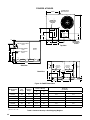
Figure10.R8GEDimensions............................... 24
Table9.CenterofGravity&ShippingWeights ..... 24
Airflow Information .......................................................25
Table10.NominalAirowRates&TempRises ... 25
Gas Information ............................................................26
Table 11. Gas Pipe Capacities ............................. 26
Table12.GasFlowRates .................................... 26
Figure11.R8GEGasValveLabel ....................... 27
Electrical Information....................................................28
Figure 12. Wiring Diagram for 208/230 V Units .... 28
Figure 13. Wiring Diagram for 460 V Units ........... 29
R8GEChargingCharts ................................................30
Figure 14. Charging Chart for 3 Ton Units ............ 30
Figure 15. Charging Chart for 4 Ton Units ............ 30
Figure 16. Charging Chart for 5 Ton Units ............ 31
FRENCH TRANSLATIONS .............................................
............
INSTALLER INFORMATION

4
IMPORTANT SAFETY INFORMATION
Safety markings are used frequently throughout this
manual to designate a degree or level of seriousness and
should not be ignored. WARNING indicates a potentially
hazardous situation that if not avoided, could result in
personal injury or death. CAUTION indicates a potentially
hazardous situation that if not avoided, may result in minor
or moderate injury or property damage.
OPERATING INSTRUCTIONS
NOTE: Thermostat styles vary. Some models may not
include the AUTO mode and others will have the AUTO
in place of the HEAT and COOL. Others may include all
three. Please refer to the thermostat manufacturer’s User
manual for detailed programming instructions.
NOTE: If the temperature level is re-adjusted, or the
system mode is reset, the fan and compressor in the
outdoor unit may not start immediately. A protective timer
circuit holds the compressor and the outdoor fan off for
approximately three minutes following a previous operation
or the interruption of the main electrical power.
1. Set the thermostat’s system mode to COOL or AUTO
and change the fan mode to AUTO. See Figure 1.
2. Set the temperature selector to the desired temperature
level. The outdoor fan, compressor, and blower motor will
all cycle on and off to maintain the indoor temperature
at the desired cooling level.
1. Set the thermostat’s system mode to HEAT or AUTO
and change the fan mode to AUTO. See Figure 1.
2. Set the temperature selector to the desired temperature
level. The compressor, outdoor fan, and blower motor
will cycle on and off to maintain the indoor temperature
at the desired heating level.
Change the thermostat’s system mode to OFF and the fan
mode to AUTO (See Figure 1). NOTE: The system will not
operate, regardless of the temperature selector setting.
The continuous indoor blower operation is typically used to
circulate the indoor air to equalize a temperature unbalance
due to a sun load, cooking, or fireplace operation.
SetthethermostatfanmodetoON(Figure1).Theindoor
blower starts immediately, and will run continually until
the fan mode is reset to AUTO.
The continuous indoor blower operation can be obtained
with the thermostat system mode set in any position,
including OFF.
UNIT MAINTENANCE
Proper maintenance is most important to achieve the best
performance from the appliance and should be performed
frequently at the beginning of each air conditioning season.
WARNING:
• Keeptheoutdoorunitclean.Hoseoffperiodicallyand
keep unit fins clear of leaves and grass clippings.
• Keep the outdoor unit clear of obstructions.
DONOTobstructairowwithtallplantsorshrubs.DO
NOTstoregasolineorotherammablematerialsonor
near the outdoor unit.
• Neveroperatetheappliancewithoutalterinstalledin
the return air duct. Inspect filters frequently and replace
when necessary with filter of same dimensional size.
TROUbLESHOOTING
If the unit fails to operate, check the following:
• Checkthethermostatsetting.Makesurethesystem
mode and temperature settings are correct.
• Checktheelectricalpanelfortrippedcircuitbreakers.
• Checktheltersfordustaccumulation.
• Checktheoutdoorunitandmakesureitiscleanand
not covered with grass or leaves.
• Iftheitemsabovedon’tresolveyourproblems,then
call your nearest service technician.
USER INFORMATION

5
IMPORTANT SAFETY INFORMATION
Please read all instructions before servicing this equipment.
Pay attention to all safety warnings and any other special
notes highlighted in the manual. Safety markings are
used frequently throughout this manual to designate a
degree or level of seriousness and should not be ignored.
WARNING indicates a potentially hazardous situation that
if not avoided, could result in personal injury or death.
CAUTION indicates a potentially hazardous situation that
if not avoided, may result in minor or moderate injury or
property damage.
WARNING:
CAUTION:
WARNING:
WARNING:
WARNING:
WARNING:
WARNING:
• TheinstallationmustconformwiththeNationalFuelGas
Code(ANSI2223.1,NFPA-54).Canadianinstallations
mustconformwithCAN/CGA-B149installationcodes.
• The installer must comply with all local codes and
regulations which govern the installation of this type
of equipment. Local codes and regulations take
precedence over any recommendations contained in
these instructions. Consult local building codes and the
NationalElectricalCode(ANSICI)forspecialinstallation
requirements.
• Thisequipmentcontainsliquidandgaseousrefrigerant
under high pressure. Installation or servicing should only
be performed by qualified trained personnel thoroughly
familiar with this type equipment.
INSTALLER INFORMATION

6
• Allelectricalwiringmustbecompletedinaccordance
with local, state and national codes and regulations
andwiththeNationalElectricCode(ANSI/NFPA70)
or in Canada the Canadian Electric Code Part 1 CSA
C.22.1.
• Air Ducts must be installed in accordance with the
standardsoftheNationalFireProtectionAssociation
“Standards for Installation of Air Conditioning and
Ventilation Systems” (NFPA 90A), “Standard for
InstallationofResidenceTypeWarmAirHeatingandAir
ConditioningSystems”(NFPA90B),theseinstructions,
and all applicable local codes.
• Installthisunitonlyinalocationandpositionasspecied
on page 7. This unit is designed only for outdoor
installations and should be located with consideration
of minimizing the length of the supply and return ducts.
Consideration should also be given to the accessibility of
fuel, electric power, service access, noise, and shade.
• Before beginning the installation, verify that the unit
model is correct for the job. The unit model number
is printed on the data label. Follow all precautions in
the literature, on tags, and on labels provided with
the equipment. Read and thoroughly understand
the instructions provided with the equipment prior to
performing the installation and operational checkout of
the equipment.
• Useonlywiththetypeofgasapprovedforthisunit.
Refertotheunitratingplate.
• Provideadequatecombustionandventilationairtothe
unit. See pages 7 - 9.
• Provideadequateclearancesaroundtheairventintake
terminal. See page 8.
• Combustion products must be discharged outdoors.
Connect this unit to an approved vent system only, as
specified on page 8.
• Never test for gas leaks with an open ame. Use
a commercially available soap solution to check all
connections (See page 17).
• ConsultTable10(page25),andtheratingplateforthe
proper circulating air flow and temperature rise. It is
important that the duct system be designed to provide
the correct flow rates and external pressure rise. An
improperly designed duct system can result in nuisance
shutdowns, and comfort or noise issues.
• Installationofequipmentmayrequirebrazingoperations.
Installer must comply with safety codes and wear
appropriate safety equipment (safety glasses, work
gloves, fire extinguisher, etc.) when performing brazing
operations.
• ThisequipmentisNOT to be used for temporary heating
of buildings or structures under construction.
REQUIREMENTS & CODES
CGA b149.1.
Additional codes listed below are for reference purposes
only and do not necessarily have jurisdiction over local or
state codes. Local codes and regulations take precedence
over any recommendations contained in these instructions.
Always consult with local authorities before installing any
gas appliance.
• US:NationalFuelGasCode(NFGC),AirforCombustionand
Ventilation
• CANADA: Natural Gas and Propane Installation Codes
(NSCNGPIC),VentingSystemsandAirSupplyforAppliances
• USandCANADA:AirConditioningContractorsAssociation
(ACCA) Manual D, Sheet Metal and Air Conditioning
ContractorsNationalAssociation(SMACNA),orAmerican
Society of Heating, Refrigeration, and Air Conditioning
Engineers(ASHRAE)FundamentalsHandbook
• US:NationalElectricalCode(NEC)ANSI/NFPA70
• CANADA:CanadianElectricalCodeCSAC22.1
• US:NFGCandNationalPlumbingCodes
• CANADA:NSCNGPIC
• US:Current edition of the NFGC and the NFPA 90B.For
copies,contacttheNationalFireProtectionAssociationInc.,
Batterymarch Park, Quincy, MA 02269; or American Gas
Association,400N.Capitol,N.W.,WashingtonDC20001or
www.NFPA.org
• CANADA:NSCNGPIC.Foracopy,contactStandardSales,
CSA International, 178 Rexdale Boulevard, Etobicoke
(Toronto),Ontario,M9W1R3Canada
• US:(NFGC)NFPA54–1999/ANSIZ223.1andtheInstallation
Standards, Warm Air Heating and Air Conditioning Systems
ANSI/NFPA90B.
• CANADA:CAN/CGA-B149.1and.2–M00NationalStandard
ofCanada.(NSCNGPIC)

7
GENERAL INFORMATION
TheR8GESinglePackageGasHeating/ElectricCooling
Unit is designed only for outdoor rooftop or ground level
installations and can be readily connected to the high
static duct system of a home. This unit has been tested
for capacity and efciency in accordance with A.R.I.
Standards and will provide many years of safe and
dependable comfort, providing it is properly installed
and maintained. With regular maintenance, this unit will
operate satisfactorily year after year. Abuse, improper
use, and/or improper maintenance can shorten the life
of the appliance and create unsafe hazards.
To achieve optimum performance and minimize equipment
failure, it is recommended that periodic maintenance be
performed on this unit. The ability to properly perform
maintenance on this equipment requires certain tools
and mechanical skills.
√ The cooling load of the area to be conditioned must be
calculated and a system of the proper capacity selected.
It is recommended that the area to be conditioned be
completely insulated and vapor sealed.
√ Check the electrical supply and verify the power supply
is adequate for unit operation. Consideration should be
given to availability of electric power, service access,
noise, and shade. If there is any question concerning
the power supply, contact the local power company.
√ All units are securely packed at the time of shipment and
upon arrival should be carefully inspected for damage
prior to installing the equipment at the job site. Verify
coil fins are straight. Claims for damage (apparent or
concealed) should be filed immediately with the carrier.
√ Survey the job site to determine the best location for
mounting the outdoor unit. Choose an appropriate
location that minimizes the length of the supply and
return air ducts.
√ Please consult your dealer for maintenance information
and availability of maintenance contracts. Please read
all instructions before installing the unit.
• Selectasolid,levelposition,preferablyonaconcrete
slab, slightly above the grade level, and parallel to the
home. DO NOT PLACE UNIT UNDER THE HOME.
• Overhead obstructions, poorly ventilated areas, and
areas subject to accumulation of debris should be
avoided. Do not place the unit in a confined space or
recessed area where discharge air from the unit to re-
circulate into the condenser air inlet, through the coil.
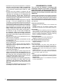
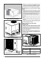
• Sufcientclearanceforunobstructedairowthroughthe
louvered control access panel and outdoor coil must be
maintained in order to achieve rated performance. See
Figure 2 for minimum clearances to obstructions.
• Aclearanceofatleast36inchesfromthebloweraccess
panel and from the louvered control access panel is
recommended for servicing and maintenance.
• Thehotcondenserairmustbedischargedupandaway
from the home, and if possible, in a direction with the
prevailing wind.
• Ifpractical,placetheairconditioneranditsductsinan
area where they will be shaded from the afternoon sun,
when the heat load is greatest.
This unit should be sized to provide the design heating
load requirement. Heating load estimates can be made
using approved methods available from Air Conditioning
Contractors of America (Manual J); American Society of
Heating,Refrigerating,andAirConditioningEngineers;
or other approved engineering methods. For installations
above 2,000 ft., the unit should have a sea level input
rating large enough that it will meet the heating load after
deration for altitude.
COMbUSTION AIR REQUIREMENTS
WARNING:
Provisions must be made during the installation of this
unit that provide an adequate supply of air for combustion.
• Instructions for determining the adequacy of an
installation can be found in the current revision of the
NFGC(ANSIZ223.1/NFPA54).
. These requirements are for
USinstallationsasfoundintheNFGC.
• TherequirementsinCanada(B149.1)arestructured
differently. Consult with B149.1 and local code officials
for Canadian installations.
Air openings in the door of the unit, warm air registers, and
return air grilles must never be restricted. If the unit does
not receive an adequate supply of air for combustion, the
flame roll-out control located above the burners will open,
turning off the gas supply to the burners. This safety device
is a manually reset switch. IMPORTANT NOTE: DO NOT
.
If this control must be replaced, use only factory authorized
replacementparts.SeetheReplacementPartsListon
page 23.

8
control area of this unit.
The following list summarizes the requirements for the
location of the vent system termination:
• Thelocationoftheventterminationmustbeconsistent
withtheNationalFuelGasCode(ANSIZ223.1)orCAN/
CGA-B149 Installation Codes.
• Theventterminationmustbelocatedatleast4feet
horizontally from any electric meters, gas meters,
regulators, and relief equipment.
• Theventterminationmustbelocatedatleast3feet
above any forced air inlet located within 10 feet.
• Theventterminationmustbelocatedatleast4feet
below, 4 feet horizontally from, or 1 foot above any
door, window, or gravity air inlet into any building.
• Theventterminationmustbelocatedatleast1foot
above grade.
• Theunitshouldbeinstalledinawaythatpreventsany
obstruction of the vent termination during accumulating
snow.
• Theunitinstallationshallavoidareaswherecondensate
drainage may cause problems by dropping on planters
or patios, etc. Also verify exhaust gases will not
impinge on windows or building surfaces, which may
be compromised or damaged by condensation.
• Donotinstalltheunitsuchthatexhaustfromthevent
termination is directed into window wells, stairwells,
under decks, or in alcoves or similarly recessed areas.
The vent termination must not be located above any
public walkways.
Figure 3 shows the proper installation of the vent cover
assembly over the vent outlet on the exterior of the corner
panel. The fasteners used to secure the vent cover
assembly have been included in the owner’s package.
WARNING:
To maximize heat exchanger life, the combustion air
must be free of chemicals that can form corrosive acidic
compounds in the combustion gases. The recommended
source of combustion air is to use clean air from outside.
•Gasoline/Kerosene
•Permanentwavesolutions
•Chlorinatedwaxesandcleaners
•Chlorinebasedswimmingpoolchemicals
•Watersofteningchemicals
•De-icingsaltsorchemicals
•Carbontetrachloride
•Halogentyperefrigerants
•Cleaningsolvents
•Cements,glues,paintremovers,varnishes,etc.
•Hydrochloricacid
•Masonryacidwashingmaterials
•PlumbingStack
This unit has been equipped with an integral venting
system and designed to operate only with this venting
system.Noadditional ventingshall beused.This unit
must be vented to the outdoors.
WARNING:
A vent cover assembly has been supplied with the unit.
and can be found secured to the gas controls within the
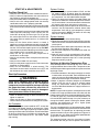
Minimum Required
Clearances to Combustibles
36"
36"
36"
TOP OF UNIT
TO BE
UNOBSTRUCTED
See Note 1
See Note 2
NOTE 1: 6” When coil is present on duct side.
NOTE 2: 1” When no coil is present on duct side.

9
WARNING:
CARbON MONOXIDE POISONING HAZARD
RISQUE D’EMPOISONNEMENT AU
MONOXYDE DE CARbONED
b149.1.

10
CIRCULATING AIR SUPPLY
WARNING:
Air Ducts
This unit is designed only for use with a supply and return
duct. Air ducts should be installed in accordance with the
standards of the National Fire Protection Association
“Standard for Installation of Air Conditioning Systems”
(NFPA90A),“StandardforInstallationofResidenceType
WarmAirHeatingandAirConditioningSystems”(NFPA
90B),andallapplicablelocalcodes.NFPApublications
are available by writing to: National Fire Protection
Association, Batterymarch Park, Quincy, ME 02269 or
visitwww.NFPA.orgontheweb.
• DesigntheductworkaccordingtoManualDbytheAir
Conditioning Contractors of America (ACCA).
• Theductsmustbeproperlysizedandnotexceed0.2”
W.C. pressure drop at 400 scfm per nominal ton of
cooling capacity.
• Ductworkshouldbeattacheddirectlytotheunitanges
for horizontal applications.
• Ifroofcurbisinstalled,theductsmustbeattachedto
the curb hangers, not the unit.
• It is recommended that the outlet duct be provided
with a removable access panel. The opening should
be accessible when the unit is installed in service and
shall be sizes so that smoke or reflected light may be
observed inside the casing to indicate the presence of
leaks in the heat exchanger. The cover for the opening
shall be attached in a way that will prevent leaks.
• If outside air is utilized as return air to the unit for
ventilation or to improve indoor air quality, the system
must be designed so that the return air to the unit is
not less than 50° F (10° C) during heating operation.
• Ifacombinationofindoorandoutdoorairisused,the
ducts and damper system must be designed so that the
return air supply to the furnace is equal to the return air
supply under normal, indoor return air applications.
AirFilterRequirements
WARNING:
• A suitable air filter must be installed upstream of the
evaporatorcoilofthereturnairsystem.RefertoTable
1 for recommended filter sizes.
• All return air must pass through the filters before entering
the evaporator coil. It is important that all filters be kept
clean and replaced frequently to ensure proper operation
of unit. Dirty or clogged filters will reduce the efficiency
of the unit and result in unit shutdowns.
• Air filter pressure drop must not exceed 0.08 inches WC.
• DownowInstallationsrequireaninternallteraccessory
kit to be installed.
• HorizontalInstallationsrequiretheairltersystembe
installed in the return air ductwork.
NOTE TO INSTALLER: After installing or replacing the
filtration system for this unit, add the following statement
on or adjacent to the filter service panel:
NOMINAL
COOLING
APPROXIMATE
AIR FLOW
APPROXIMATE
FILTER AREA
RECOMMENDED
FILTER SIZE
3.0 1,100 - 1,300 625 25 x 25
4.0 1,400 - 1,800 850 18 x 24 (2 required)
5.0 1,800 - 2,200 1,000 20 x 25 (2 required)
* Based on velocity of 300 ft/min for disposable filters and 500 ft/min
for high velocity (cleanable) Filters.
Unconditioned Spaces
All duct work passing through unconditioned space must
be properly insulated to minimize duct losses and prevent
condensation. Use insulation with an outer vapor barrier.
Refertolocalcodesforinsulationmaterialrequirements.
Acoustical Duct Work
Certain installations may require the use of acoustical
lining inside the supply duct work.
• Acousticalinsulationmustbeinaccordancewiththe
current revision of the Sheet Metal and Air Conditioning

11
ContractorsNationalAssociation(SMACNA)application
standard for duct liners.
• DuctliningmustbeULclassiedbattsorblanketswith
a fire hazard classification of FHC-25/50 or less.
• Fiberductworkmaybeusedinplaceofinternalduct
liners if the fiber duct work is in accordance with the
currentrevisionoftheSMACNAconstructionstandard
on fibrous glass ducts. Fibrous duct work and internal
acousticalliningmustbeNFPAClass1airductswhen
tested per UL Standard 181 for Class 1 ducts.
UNIT INSTALLATION
Remove the shipping carton and User’s Manual from
the equipment. Take care not to damage the tubing
connections when removing the carton. For rooftop
installations, remove and discard the two supports attached
beneath the unit.
WARNING:
R8GE units are certied as combination heating and
cooling equipment for outdoor rooftop or ground level
installations. Units may be installed on combustible
flooring or Class A, B, or C roofing material when used
with bottom supply and return air ducts as long as the
following requirements are met:
• If using horizontal supply and return air ducts, the
horizontal roof curb kit and return air kit must be installed
prior to unit installation. Horizontal roof curb is required.
• Ifusingbottomdischargewithreturnairductsaroofcurb
mustbeinstalledpriortounitinstallation.SeeRigging
and Hoisting section for setting of the unit.
• Sufcient clearance forunobstructed airowthrough
the outdoor coil must also be maintained in order to
achieve rated performance. See page 7 for information
about locating the equipment.
Ground level installations must be located according to
local building codes or ordinances and these requirements:
• Clearancesmustbeinaccordancewiththoseshown
in Figure 2 (page 7).
• Asuitablemountingpad(Figure4,page12)mustbe
provided and be separate from the building foundation.
The pad must be level to ensure proper condensate
disposal and strong enough to support the unit’s weight.
The slab height must be a minimum of 2” (5cm) above
grade and with adequate drainage.
• Unitsrequirehorizontalroofcurbandreturnairkitfor
horizontal installations.
• Ductwork should be attached directly to anges on
panels supplied in horizontal duct conversion kits.
Rooftopinstallationsmustbelocatedaccordingtolocal
building codes or ordinances and these requirements:
• Theroofmustbecapableofhandlingtheweightofthe
unit.Forunitweights,seeTable9.Reinforcetheroof
if necessary.
• Theappropriateaccessoryroofcurb(Figure5,page12)
must be installed prior to unit installation. The roof curb
must be square and level to ensure proper condensate
drainage.
• Secure roof curb or frame to roof using acceptable
mechanical methods per local codes. NOTE: Make sure
the two supports beneath the unit have been removed.
Condensate is removed from the unit through the 3/4”
female pipe fitting (Figure 6, page 12) located on the front
side of the unit. Install a 2 inch condensate trap in the
drain line of the same size and prime with water. When
connecting rigid drain line, hold the female fitting with a
wrench to prevent twisting. Refer
to local codes and restrictions for proper condensate
disposal requirements.
The unit is shipped ready for horizontal duct connections.
If down flow ducts are required, the unit must be converted
following the steps below for both the supply and return
ducts.
1.Removethehorizontalductcap.
2. Locate the duct cap inside the duct openings and remove
the screw holding it in place.
3. Lift the cap out of the unit. (The cap can be pushed
up from the bottom by reaching through the fork slot).
4. Cover the horizontal duct opening with the horizontal
duct cap. The insulation will be on the indoor side.
5. Fasten the cover with screws to seal.
1.Removethereturnairpanelfromtheunit.
2.Removetheheightadjustmentscrewfromtheinside
of the rack.

12
Condensate Drain
UNIT SIZE INTERNAL FILTER SIZE
R8GE-X36
(2) 16” x 25” x 1”
or
(2) 16” x 25” x 2”
R8GE-X48/X60
(2) 18” x 25” x 1”
or
(2) 18” x 25” x 2”
3.Remove(1)screwsecuringtheassemblytothecoil
located on the left leg of the rack. NOTE: The assembly
can now be easily collapsed and removed from the unit.
See Figure 7 for filter rack securing screw locations.
1.Removeaccesspanelscrewsfromreturnairpanel.
(HINT: Loosen the unit’s top panel screws near the
top edge of the access panel. The access panel was
designed to be captured underneath the top panel.)
2. Slide the first filter between both guide channels of filter
rack and allow the filter to drop easily into place.
3. Verify the bottom of the filter is within the channels of
the rack.
4. Slide the 2nd filter between both guide channels of filter
rack.
5. Verify the bottom of the filter is within the channels of
the rack.
6.Replaceaccesscoverbyslidingthetopedgeofpanel
under the lip of the unit’s top panel. Secure access
panel by replacing the screws.
1.Removeaccesspanelscrewsfromreturnairpanel.
( Loosen the unit’s top panel screws near the
top edge of the access panel. The access panel was
designed to be captured underneath the top panel.)
2.Removeupperlterbygentlypullinglterthroughthe
access panel opening.
3.Removelowerlterbyliftingmediatotopoflterrack.
Removeinthesamemannerasdescribedinstep2.
4. Install new filter in the filter rack as described in the
previous section.
FILTER RACK
SECURING
SCREWS

ELECTRICAL WIRING
WARNING:
• Allelectricalconnectionsmustbeincompliancewith
all applicable local codes and ordinances, and with
the current revision of the National Electric Code
(ANSI/NFPA70).
• ForCanadian installations theelectricalconnections
and grounding shall comply with the current Canadian
Electrical Code (CSA C22.1 and/or local codes).
√ Verify the voltage, frequency, and phase of the supply
source match the specifications on the unit rating plate.
√ Verify that the service provided by the utility is sufficient
to handle the additional load imposed by this equipment.
See Table 3 or the unit wiring label for proper high and
low voltage wiring.
√ Verify factory wiring is in accordance with the unit wiring
diagram (Figures 12 - 13, pages 28 - 29). Verify none of
the connections loosened during shipping or installation.
• Thelinevoltagetotheunitshouldbesuppliedfroma
dedicated branch circuit containing the correct fuse or
circuit breaker for the unit.
•
This switch shall
be capable of electrically de-energizing the outdoor unit.
See unit data label for proper incoming field wiring. Any
other wiring methods must be acceptable to authority
having jurisdiction.
• Useonlycopperwireforthelinevoltagepowersupply
to this unit (Table 4, page 14). Use proper code agency
listed conduit and a conduit connector for connecting
the supply wires to the unit. Use of rain tight conduit is
recommended.
• Providepowersupplyfortheunitinaccordancewith
the unit wiring diagram and the unit rating plate.
• Overcurrentprotectionmustbeprovidedatthebranch
circuit distribution panel and sized as shown on the unit
rating label and according to applicable local codes.
See the unit rating plate for maximum circuit ampacity
and maximum overcurrent protection limits.
• Awiringdiagramislocatedontheinsidecoverofthe
control access panel of the outdoor unit. The installer
should become familiar with the wiring diagram before
making any electrical connections to the outdoor unit.
See Figures 12 - 13.
• Ifanyoftheoriginalwiressuppliedwiththeunitmust
be replaced, they must be replaced with material of the
same gauge and temperature rating.
• Unitsareshippedfromthefactorywiredfor240volt
transformer operation. For 208V operation, remove the
lead from the transformer terminal marked 240V and
connect it to the terminal marked 208V. Three phase,
460V units are shipped wired for 460V operation.
• Internallymountedcircuitbreakersareavailableaseld
installed options. These circuit breakers can be used
as an electrical disconnect.
• Connecttheline-voltageleadstotheterminalsonthe
contactor (or the circuit breaker if the field installed circuit
breaker kits are used) inside the control compartment.
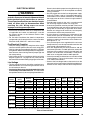
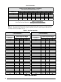
RLA LRA
R8GE-X36C
72,000 208/-230/60/3 187 253 11.6 73 1.46 3.6 20.9 30
96,000 208/-230/60/3 187 253 11.6 73 1.46 3.6 20.9 30
R8GE-X48C
96,000 208/-230/60/3 187 253 15.3 83.1 1.46 5 27 40
120,000 208/-230/60/3 187 253 15.3 83.1 1.46 5 27 40
R8GE-X60C
96,000 208/-230/60/3 187 253 17.4 110 1.46 6.5 31.1 45
120,000 208/-230/60/3 187 253 17.4 110 1.46 6.5 31.1 45
R8GE-X36D
72,000 460/60/3 414 506 6.4 38 0.6 1.9 11.9 15
96,000 460/60/3 414 506 6.4 38 0.6 1.9 11.9 15
R8GE-X48D
96,000 460/60/3 414 506 6.9 41 0.6 3.3 13.9 20
120,000 460/60/3 414 506 6.9 41 0.6 3.3 13.9 20
R8GE-X60D
96,000 460/60/3 414 506 8.6 52 0.6 3.3 16 20
120,000 460/60/3 414 506 8.6 52 0.6 3.3 16 20
FLA=FullLoadAmps;LRA=LockRotoramps;RLA=RatedLoadAmps.

14
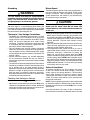
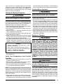
Voltage unbalance occurs when the voltages of all phases
of a 3-phase power supply are no longer equal. This
unbalance reduces motor efficiency and performance.
Some underlying causes of voltage unbalance may
include: Lack of symmetry in transmission lines, large
single-phase loads, and unbalanced or overloaded
transformers. A motor should never be operated when a
phase imbalance in supply is greater than 2%.
Perform the following steps to determine the percentage
of voltage imbalance:
1. Measure the line voltages
of your 3-phase power
supply where it enters
the building and at a
location that will only
be dedicated to the
unit installation. (at the
units circuit protection or
disconnect).
EXAMPLE:
AB = 451V
BC = 460V
AC = 453V
2. Determine the average voltage in the power supply.
In this example, the measured line voltages were 451,
460, and 453. The average would be 454 volts (451 +
460 + 453 = 1,364 / 3 = 454).
3. Determine the maximum deviation:
EXAMPLE
From the values given in step 1, the BC voltage (460V)
is the greatest difference in value from the average:
460 - 454 = 6
454 - 451 = 3
454 - 453 = 1
4. Determine percent of
voltage imbalance by
using the results from
steps2&3inthefollowing
equation.
6
454
100 x
= 1.32%
EXAMPLE
maxvoltage deviation
fromaverage voltage
=100 x
averagevoltage
% Voltage Imbalance
The amount of phase imbalance (1.32%) is satisfactory
since the amount is lower than the maximum allowable
2%. Please contact your local electric utility company if
your voltage imbalance is more than 2%.
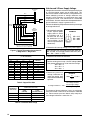
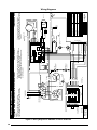
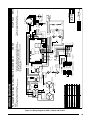
Gas
Valve
1
2
3
4
5
6
7
8
9
Economizer
Plug
Indoor
Thermostat
Sub-Base
Furnace
Board
(Optional, Check
thermostat Instructions)
Optional Commercial Thermostat Only
(Occupied / unoccupied - If Equipped)
R
R
W1
W1
G
G
C
X
Y1
Y1
A1
Y2
A1
Green
Gray
Black
Yellow
White
Y2
Blue
COPPER WIRE SIZE — AWG
SUPPLY CIRCUIT
AMPACITY
200 150 100 50
6 8 10 14 15
4 6 8 12 20
4 6 8 10 25
4 4 6 10 30
3 4 6 8 35
3 4 6 8 40
2 3 4 6 45
2 3 4 6 50
2 3 4 6 55
1 2 3 4 60
WireSizebasedonN.E.C.for60°typecopperconductors.
THERMOSTAT
WIRE GAUGE
24 55 25
22 90 45
20 140 70
18 225 110

15
WARNING:
!
This unit must be electrically grounded in accordance
with local codes or, in the absence of local codes, with
theNationalElectricalCode(ANSI/NFPA70)ortheCSA
C22.1 Electrical Code. Use the grounding lug provided in
the control box for grounding the unit.
• TheR8GEunitisdesignedtooperatefroma24VAC
Class II control circuit. The control circuit wiring must
complywiththecurrentprovisionsoftheNEC(ANSI/
NFPA 70) and with applicable local codes having
jurisdiction. Thermostat connections should be made
in accordance with the instructions supplied with the
thermostat and the indoor equipment.
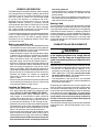
• The low voltage wires must be properly connected.
Route24Vcontrolwiresthroughthesealinggrommet
nearthepowerentrance.Recommendedwiregauge
and wire lengths for typical thermostat connections are
listed in Table 5.
• Several thermostat options are available depending
on the accessories installed with the unit. Select a
thermostat that operates in conjunction with the installed
accessories.
• Thethermostatshouldbemountedabout5feetabove
theooronaninsidewall.DONOTinstallthethermostat
on an outside wall or any other location where its
operation may be adversely affected by radiant heat from
fireplaces, sunlight, or lighting fixtures, and convective
heat from warm air registers or electrical appliances.
Refertothethermostatmanufacturer’sinstructionsheet
for detailed mounting information.
Checking Heat Anticipator Settings
• Addthecurrentdrawofthesystemcomponents.
OR
• MeasurethecurrentowonthethermostatR-W circuit
after the circulating blower motor has started. Set the heat
anticipator according to the thermostat manufacturer’s
instructions for heat anticipator settings.
The blower speed is preset at the factory for operation at
the same speed for heating and cooling. These factory
settings are listed in Table 10 (page 25). For optimum
system performance and comfort, it may be necessary
to change the factory set speed.
CAUTION:
1. Shut off all electrical power to the unit and remove the
blower panel. Locate the orange, red and blue wires
terminated to the blower motor. NOTE: The orange wire
controls cooling operation while the red wire controls
heating operation. The blue wire controls fan-only
operation.
2. Verify the required speed from the airflow data found in
Table 10. Place appropriate wire on the correct motor
speed tap for the required airflow point.
3. The integrated furnace control can be set to a 2 or 3
speed mode. When a G only call is received from the
thermostat (indicating a continuous fan mode), the
blower will run the heating speed when the
mode is selected using the jumper on the control board
(factory setting). When mode is selected, the fan
only speed may be different than the heating or cooling
speed. If no jumper is present, the control defaults to the
mode of operation. A call for heating or cooling
takes priority over fan only mode
An optional humidistat may be installed in the return
air duct for humidity control (when needed), maximum
system capacity and energy efficiency. The humidistat
senses when humidity in the return air stream is above
a preset level and sends a signal to the motor to reduce
airflow. This allows more moisture to be removed until
the humidity level drops.
NOTE: The packaged heat pump unit is pre-programmed
forhumidistatoperation.Removethejumperconnector
between the two terminals marked HUM on the variable
speed board.
Install the humidistat in the return air duct as directed in
the installation instructions included with the kit. Wire the

16
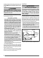
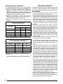
WARNING:
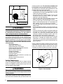
FIRE OR EXPLOSION HAZARD
After the gas piping to the unit is complete, all connections
must be tested for gas leaks. This includes pipe connections
at the main gas valve, emergency shutoff valve and
other gas connectors. A soap and water solution can be
applied on each joint or union using a small paintbrush.
If any bubbling is observed, the connection is not sealed
adequatelyandmustberetightened.Repeatthetightening
and soap check process until bubbling ceases.
•
•
Ground
Joint
Union
Dripleg
Shut-Off Valve
with
1
/8 NPT
plugged tap
Burner
Assembly
Manifold
Some utilities
require Shut-Off
Valve to be
4 to 5 feet
above floor
Automatic Gas Valve
(with manual shut-off)
humidistat through the low-voltage wire entrance in the
packaged heat pump unit to the quick-connect terminals
(marked Wire the humidistat to open on rise in
humidity.
CAUTION:
Check all factory wiring to the units wiring diagram. Inspect
the factory wiring connections to be sure none loosened
during shipping or installation.
GAS SUPPLY & PIPING
This unit only has right side gas entry. When connecting
the gas, provide clearance between the gas supply line
and the entry hole in the unit’s casing to avoid unwanted
noise and/or damage to the unit. A typical gas service
hookup is shown in Figure 8.
Table 11 (page 26) lists gas pipe capacities for standard
pipe sizes as a function of length in typical applications
based on nominal pressure drop in the line.

17
Conversion of this unit must be performed by qualified
service personnel, using only approved parts. All
installationsmustbemadeinaccordancewiththeNational
Fuel Gas Code and/or local jurisdiction codes.
WARNING:
High altitude conversion can be field performed by a
simple adjustment of manifold pressure or a change of
the orifices (if necessary) as described on page 20. The
changes required depend on the installation altitude and
the heating value of the gas (based on sea level) which
can be obtained from your local gas utility. The heating
value of gas at high altitude is always lower than the sea
level heating value. The heating values listed in Tables
6&7(page20)arebasedonsealevelvalues.
If installing this unit above 2,000 feet, the input rate must
be reduced 4% per 1,000 feet of altitude (Example: 12%
at 3,000 feet, 16% at 4,000 feet, etc). NOTE: Deration is
necessary to compensate for low atmospheric pressure
at high altitudes.
For altitudes between 5,000 and 10,000 feet above sea
level, the unit can be converted by adjusting the furnace
manifold pressure. See Tables 6 or 7 for the correct
manifold pressure settings.
WARNING:
Conversion of this equipment to LP/Propane gas must
be made by qualified service personnel, using approved
factory parts. Conversion to LP can be accomplished by
replacing the natural gas orifices with the appropriate LP/
Propane orifices and then adjusting the manifold pressure
(page 20). Conversion to LP/Propane (sea level and high
altitude) is detailed in the installation instructions provided
with the conversion kit.
Approved conversion kits are:
• TheUnitedStatesLP/PropaneGasSeaLevelandHigh
AltitudeConversionKitisforLP/propaneconversionin
the United States at altitudes between zero and 10,000
ft. above sea level.
• TheCanadianLP/PropaneGasSeaLevelandHigh
AltitudeConversionKitisforLP/propaneconversions
in Canada at altitudes between zero and 4,500 ft. above
sea level.
For installations between zero and 4,999 ft. above sea
level, a #54 drill size orifice should be used. Installations
5,000 ft. above sea level require a # 55 drill size orifice.
Table 7 (page 20) lists the correct orifice size to use at
different altitudes.
After changing the orifices, it is required that you measure
the gas input rate by clocking the gas meter and using
the local gas heating value. See Verifying and Adjusting
theFiringRatesectiononpage19.

18
START UP & ADJUSTMENTS
√ Verify the unit is level and allows condensate to drain.
√ Verify all clearance requirements are met and there is
free airflow to and from the outdoor coil.
√ Verify that the duct work is sealed to prevent air leakage.
√ Verify that the line voltage power leads are securely
connected and the unit is properly grounded.
√ Verify that the low voltage wires are securely connected
to the correct leads in the low voltage area of the control
box.
√ Verify that the gas line service pressure does not exceed
10.0 inches WC (0.36 psig), and is not less than 4.5
inches WC (0.16 psig) for natural gas. For LP gas the
line service pressure must not exceed 14 inches WC
(0.51 psig) and must not be less than 11.0 inches WC
(0.40 psig).
√ Verify that the flame roll-out control is closed. If
necessary, press the red button to reset the control. DO
NOT install a jumper wire across the control to defeat its
function. If the control reopens upon start-up, DO NOT
reset the control without identifying and correcting the
fault condition which caused the control to trip.
√ Verify that the gas line has been purged and all
connections are leak tight.
√ Verify that all exterior panels are replaced and securely
fastened.
√ Verify that the outdoor fan turns freely.
√ Verify that the power supply branch circuit overcurrent
protection is sized properly.
√ Verify that the thermostat is wired correctly. The
thermostat function switch should be set to OFF and
the thermostat fan switch should be set to AUTO.
WARNING:
• Checkallelectricalwiringforlooseconnectionsand
tighten as required.
• Checkunitforreturnairltersandcondensatetrap.
• Closeallelectricaldisconnectstoenergizethesystem.
Air Circulation
Leave the thermostat system mode on OFF, and set the
fanmodetoON.Blowershouldruncontinuously.Check
the air delivery at the supply registers and adjust register
openings for balanced air distribution. Examine ductwork
for leaks or obstruction if insufficient air is detected. Set
the thermostat fan mode to AUTO. The blower should
stop running.
System Cooling
1. Set the thermostat’s system mode to COOL and the
fan mode to AUTO. Gradually lower the thermostat
temperature setpoint below room temperature and verify
the compressor, fan and indoor blower energize.
2. Feel the air being circulated by the indoor blower and
verify that it is cooler than ambient temperature. Listen for
any unusual noises. If unusual sounds occur, determine
the source of the noise and correct as necessary.
3. Allow the cooling system to operate for several minutes
and then set the temperature selector above room
temperature. Verify the fan and compressor cycle off
with the thermostat. NOTE: The blower will also stop
after an 85 - 90 second delay.
System Heating
1. Set the thermostat to the lowest setting.
2. Follow the procedures given on the operating instruction
label, this manual or attached inside the louvered control
access panel.
3. Set the thermostat above room temperature and verify
the Operating Sequence. See page 20.
4. Verify that the compressor and outdoor fan motor are
not energized.
5. After the unit has run for approximately five minutes,
set the thermostat below room temperature and verify
the shutdown sequence; steps 10 -12 in the Operating
Sequence section (page 20).
Verify the temperature rise through the unit is within the
range specified on the unit data label. Temperature rises
outside the specified range could result in premature heat
exchanger failure.
1. Place thermometers in the return and supply air stream
as close to the unit as possible. The thermometer on the
supply air side must be shielded against direct radiation
from the heat exchanger to avoid false readings.
2. Adjust all registers and duct dampers to the desired
position. Run the unit for 10 to 15 minutes before
taking any temperature readings. The temperature
rise is the difference between the supply and return air
temperatures.
NOTE: For typical duct systems, the temperature rise will
fall within the range specified on the data label (with the
blower speed at the factory recommended setting) shown
in Table 10 (page 25). If the measured temperature rise
falls outside the specified range, it may be necessary to
change the blower speed. Lowering the blower speed
increases the temperature rise and a higher speed
decreases the temperature rise.
The unit is equipped with a variable speed motor. Speed
selection is made by moving the leads on the blower motor
terminal block. The speed taps for adjusting the motor
speed are shown in the unit wiring diagram or Figures 12
&13(pages28-29).RefertotheBlowerSpeedSection
(page 15) for additional information.
The integrated control starts the circulating air blower
30 seconds after the gas valve is opened. The control is

19
factory wired to turn the blower motor off 135 seconds
afterthegasvalveisclosed.NOTE:Theheatingblower
off delay is factory set at 90 seconds. An additional 45
second off delay is programmed into the X-13 blower
motor for a total of 135 seconds.
CAUTION:
The firing rate must be verified for each installation to
prevent over-firing of the furnace.
. To
determine the firing rate, follow the steps below:
1. Obtain the gas heating value (HHV) from the gas supplier.
2. Shut off all other gas fired appliances.
3. Start the unit in heating mode and allow it to run for at
least 3 minutes.
4. Measure the time (in seconds) required for the gas
meter to complete one revolution.
5. Convert the time per revolution to cubic feet of gas per
hour using Table 13 (page 27).
6. Multiply the gas flow rate in cubic feet per hour by the
heating value of the gas in Btu per cubic foot to obtain
the firing rate in Btu per hour. See Example.
7. Adjust the manifold pressure if necessary. See Manifold
Pressure Adjustment instructions on page 20. For
additional information about elevations above 2,000
:
• Timefor1revolutionofagasmeterwitha1cubic
foot dial = 40 seconds.
• FromTable13,read90cubicfeetgasperhour.
• Localheatingvalueofthegas(obtainedfromgas
supplier) = 1,040 Btu per cubic foot.
• Inputrate=1,040x90=93,600Btuh.
feet, see page 17.
1. Verify the louvered control access panel is in place and
that there is power to the unit.
2. Block the return airflow to the unit by installing a close-
off plate in place of or upstream of the filter.
3. Set the thermostat above room temperature and verify
the units operating sequence (page 20).
NOTE: The over-temperature limit control should turn off
the gas valve within approximately four minutes (exact time
depends on the efficiency of the close-off when blocking
the return air). The circulating air and combustion blowers
should continue to run when the over-temperature limit
control switch opens.
3.Removetheclose-offplateimmediatelyaftertheover-
temperature limit control opens. If the unit operates
for more than four minutes with no return air, set the
thermostat below room temperature, shut off power to
the unit, and replace the over-temperature limit control.
WARNING:
1.Removethelouveredcontrolaccesspanelandverify
there is power to the unit.
2. Set thermostat above room temperature and observe
the ignition sequence. NOTE: The burner flame should
carry over immediately between all burners without
lifting off, curling, or floating. The flames should be blue,
without yellow tips. Make sure the flame is drawn into
the center of the heat exchanger tube. In a properly
adjusted burner assembly, the flame bends down and
to the right at the end of the heat exchanger tube. The
end of the flame will be out of sight around the bend.
3. After validating flame characteristics, set the thermostat
below room temperature and verify the burner flame
extinguishes completely.
WARNING:
CAUTION:
The system refrigerant charge can be checked and
adjusted through the service ports provided at the front
panel. Use only gauge lines which have a “Schrader”
depression device present to actuate the valve. Draw a
vacuum on gauge lines to remove air before attaching
themtotheserviceportsontheunit.Refrigerantcharging
must be done by qualified personnel familiar with safe
and environmentally responsible refrigerant handling
procedures.

20
OPERATING SEQUENCE
The operating sequences for the heating, cooling, and
fanmodesaredescribedbelow.Refertotheeldand
furnace wiring diagrams (Figures 12 or 13, pages 28 - 29).
1. On a call for heat, the thermostat closes and applies
24 VAC to terminal W on the control board.
2. The control board checks for continuity on the 24 VAC
limit control circuit, over-temperature limit switch, flame
rollout switches, and blocked vent switch in series. If an
open limit is detected, the control board will energize
the inducer blower. All other system functions will be
inoperable until the limit circuit closes. While the limit
is open, the red LED will pulse at a rate of 1 blink per
unit time.
3. The furnace control checks for continuity (24 VAC)
across the pressure switch. If the pressure switch is
closed, the heat mode sequence will not continue. If it
remains closed for 10 seconds, the red LED will flash
3 times repetitively until the fault condition clears.
4. The inducer energizes (if pressure switch is open).
5. The pressure switch will close. If the pressure switch
does not close after 10 seconds, the fault LED will flash
2 times and the inducer will continue to run until the
switch is closed.
6. The inducer will pre-purge for 30 seconds and then the
igniter will start its warm-up as follows:
Initial Power up: After 30 seconds of igniter warm-up,
the gas valves (24 VAC) will open. The igniter circuit
will stay energized for 3 seconds after the gas valve
opens.
After Initial Power up: The control has a programmed
adaptive ignition feature which varies the warm-up
period as follows: If ignition is successful the warm-up
is reduced by 3 seconds on each subsequent call for
heat until ignition failure occurs. Upon ignition failure,
the warm-up is increased by 3 seconds on the next try.
If successful, the timing remains fixed at this level. In
general, whenever ignition failure occurs the warm-up
interval is increased by 3 seconds on the next try. And
if successful, it remains there. Minimum and maximum
warm-up time limits are set at 6 and 54 seconds.
7. The furnace control must prove flame via the flame
sensor 5 seconds after the gas valves open. If flame is
sensed, burners are on and the igniter cools off. If no
flame is sensed, the gas valve closes immediately and
the inducer continues to run. A second trial for ignition
(step 6) begins. If no flame is sensed on the fifth try for
ignition, the furnace control is locked and the red LED
will blink 4 times repetitively. The thermostat must be
opened for at least ten seconds to reset the furnace
control after a lock out. Otherwise, the furnace will
attempt another ignition sequence in 1 hour.
8. After the gas valve opens (30 seconds), the blower will
ramp to the selected airflow and continues to run.
9. When the thermostat has been satisfied, the W terminal
on the integrated control is de-energized.
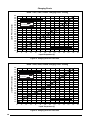
NATURAL GAS INSTALLATIONS
800 TO 899 900 TO 999
zero to 1,999 FT
3.5 3.5 3.5
2,000 to 4,999 FT 3.5 3.5 3.5
5,000 to 5,999 FT 3.5 3.5 3.0
6,000 to 7,999 FT 3.5 3.2 2.8
8,000 to 10,000 FT
3.0 2.8 2.5
MANIFOLD
PRESSURE
ORIFICE
SIZE
zero to 1,999 FT
10.0 54
2,000 to 4,999 FT 8.5 54
5,000 to 5,999 FT 10.0 55
6,000 to 7,999 FT 9.0 55
8,000 to 10,000 FT
8.5 55
NOTE: Manifold pressure based on sea level LP heating value
of 2,500 Btu/cu. ft.
3
The manifold pressure must be set to the appropriate
value for your installation. To adjust the manifold pressure:
1. Obtain the required manifold pressure setting. Use
Table 6 for natural gas or Table 7 for LP/propane gas.
NOTE: The values listed in the tables are based on sea
level values. At higher altitudes, the heating value of gas
is lower than the sea level heating value.
2.Remove the regulator cap. Turn the high fire
adjusting screw clockwise to increase the pressure or
counterclockwise to reduce the pressure.
3.Replace the regulator cap after adjustments are
complete.
La page est en cours de chargement...
La page est en cours de chargement...
La page est en cours de chargement...
La page est en cours de chargement...
La page est en cours de chargement...
La page est en cours de chargement...
La page est en cours de chargement...
La page est en cours de chargement...
La page est en cours de chargement...
La page est en cours de chargement...
La page est en cours de chargement...
La page est en cours de chargement...
-
 1
1
-
 2
2
-
 3
3
-
 4
4
-
 5
5
-
 6
6
-
 7
7
-
 8
8
-
 9
9
-
 10
10
-
 11
11
-
 12
12
-
 13
13
-
 14
14
-
 15
15
-
 16
16
-
 17
17
-
 18
18
-
 19
19
-
 20
20
-
 21
21
-
 22
22
-
 23
23
-
 24
24
-
 25
25
-
 26
26
-
 27
27
-
 28
28
-
 29
29
-
 30
30
-
 31
31
-
 32
32


Westinghouse R8GE, Three Phase Guide d'installation
- Taper
- Guide d'installation
- Ce manuel convient également à
dans d''autres langues
Documents connexes
Autres documents
-
Unbranded R6GD 3 - 5 Ton, 3 Phase Guide d'installation
-
Miller R8GE, Single Phase Guide d'installation
-
Miller H8HK Information produit
-
-
-
-
Unbranded R6GN 12.5 - 15 Ton Guide d'installation
-
Nordyne M2 Series Manuel utilisateur
-
Miller M3RL Manuel utilisateur
-
Dettson EVD-18_24 Guide d'installation