
INSTRUCTIONS FOR INSTALLATION AND MAINTENANCE
INSTRUCTIONS POUR L’INSTALLATION ET L’ENTRETIEN

Manual valid for firmware versions 2.x.y-4.x-1.x
Manuel valide pour les versions micrologiciel 2.x.y-4.x-1.x

ENGLISH
EN
38
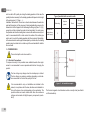
INDEX
Key 41
Warnings 41
Responsibility 42
1.
General 42
1.1 Description of the Integrated Inverter 43
1.2 Integrated expansion vessel 43
1.3 Technical characteristics 44
2. Installation 45
2.1 Vertical Conguration 45
2.1.1 Hydraulic connections 46
2.1.2 Loading operation – Installation above head and below head 46
2.2 Horizontal Conguration 47
2.2.1 Hydraulic connections 47
2.2.2 Orientation of the interface panel 47
2.2.3 Loading operation – Installation above head and below head 48
3. Commissioning 49
3.1 Electrical connections 49
3.2 Conguration of the integrated inverter 50
3.3 Priming 50
4. The keypad and the display 51
4.1 Direct access with a combination of keys 52
4.2 Access by name with a drop-down menu 55
4.3 Structure of the menu pages 55
4.4 Blocking parameter setting by Password 56
4.5 Enabling and disabling the motor 56
5. Meaning of the individual parameters 57
5.1 User Menu 57
5.1.1 Status 57
5.1.2 RS: Rotation speed display 57
5.1.3 VP: Pressure display 57
5.1.4 VF: Flow display 57
5.1.5 PO: Absorbed power display 57
5.1.6 C1: Phase current display 57
5.1.7 SV: Supply voltage 57
5.1.8 SR: Supply range 57
5.1.9 TE: Dissipator temperature display 57
5.1.10 PKm: Pressure measured at suction 57
5.1.11 Operating hours and number of starts 57
5.1.12 PI: Power histogram 57
5.1.13 Output ow meter 58
5.1.14 VE: Version display 58
5.1.15 FF: Fault log display 58
5.2 Monitor Menu 58
5.2.1 CT: Display contrast 58
5.2.2 BK: Display brightness 58
5.2.3 TK: Backlight switch-on time 58
5.2.4 LA: Language 58
5.2.5 TE: Dissipator temperature display 58
5.3 Setpoint Menu 58
5.3.1 SP: Setting the setpoint pressure 59
5.4 Manual Menu 59
5.4.1 Status 59
5.4.2 RI: Speed setting 59
5.4.3 VP: Pressure display 59
5.4.4 VF: Flow display 59
5.4.5 PO: Absorbed power display 59
5.4.6 C1: Phase current display 59
5.4.7 RS: Rotation speed display 59
5.4.8 SV: Tupply voltage 60
5.4.9 SR: Supply range 60
5.4.10 TE: Dissipator temperature display 60
5.5 Installer Menu 60
5.5.1 RP: Setting the pressure fall to restart 60
5.5.2 OD: Type of plant 60
5.5.3 MS: Measuring system 60
5.5.4 AS: Association of devices 61
5.5.5 EK: Setting the low pressure function on suction 61
5.5.6 PK: Low pressure threshold on suction 61
5.5.7 T1: Low pressure delay (function detecting low pressure on suction) 61
5.6 Technical Assistance Menu 62
5.6.1 TB: Water lack blockage time 62
5.6.2 T2: Delay in switching off 62
5.6.3 GP: Proportional gain coefcient 62
5.6.4 GI: Integral gain coefcient 62
5.6.5 RM: Maximum speed 62
5.6.6 AY: Anti Cycling 62
5.6.7 AE: Enabling the anti-block function 62
5.6.8 AF: Enabling the anti-freeze function 62
5.7 Setting low pressure detection on suction
62
5.8 RF: Fault and warning reset 63
5.8.1 PW: Change password 63
6. Protection systems 63
6.1 Description of blockages 64
6.1.1 “BL” Anti Dry-Run (Protection against dry running) 64

EN
ENGLISH
39
6.1.2 “Anti-Cycling (Protection against continuous cycles without utility request) 64
6.1.3 “Anti-Freeze (Protection against freezing of water in the system) 64
6.1.4 “BP1” Blockage due to fault of the delivery pressure sensor 65
6.1.5 “BP2” Blockage due to fault of the suction pressure sensor 65
6.1.6 “PB” Blockage due to supply voltage outside specications 65
6.1.7 “SC” Blockage due to short circuit between the motor phases 65
6.2 Manual reset of error conditions 65
6.3 Self-reset of error conditions 65
7. Reset and factory settings 66
7.1 General system reset 66
7.2 Factory settings 66
7.3 Restoring the factory settings 66
8. Particular installations 67
8.1 Inhibiting self-priming 67
8.2 Wall installation 68
9. Maintenance 68
9.1 Accessory tool 68
9.2 Emptying the system 68
9.3 Non-return valve 69
9.4 Motor shaft 69
9.5 Expansion Vessel 70
10. Troubleshooting 70
11. Updating the rmware 72
12. Disposal 72
13. Guarantee 72


EN
ENGLISH
41
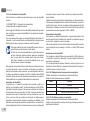
It is the responsibility of the installer to make sure that the power
supply system is equipped with an efcient grounding system
according to the regulations in force.
To improve immunity to possible noise radiating to other equip-
ment, it is advisable to use separate wiring to power the inverter.
The appliance may be used by children over 8 years old and by
persons with reduced physical, sensory or mental capacities, or
who lack experience or knowledge, on condition that they are
under supervision or after they have received instructions con-
cerning the safe use of the appliance and the understanding of
the dangers involved. Children must not play with the appliance.
Cleaning and maintenance intended to be carried out by the user
must not be performed by children without supervision.
Safety
Use is allowed only if the electric system is in possession of
safety precautions in accordance with the regulations in force in
the country where the product is installed (for Italy CEI 64/2).
Pumped liquids
The machine has been designed and made for pumping water,
free from explosive substances and solid particles or bres, with
a density of 1000 Kg/m³, a kinematic viscosity of 1mm²/s and
non chemically aggressive liquids.
The power supply cable must never be used to carry or shift the
pump.
Never pull on the cable to detach the plug from the socket.
If the power cable is damaged, it must be replaced by the manu-
facturer or by their authorised technical assistance service, so
as to avoid any risk.
Failure to observe the warnings may create situations of risk for persons
or property and will void the product guarantee.
KEY
The following symbols have been used in the discussioni:
SITUATION OF GENERAL DANGER. Failure to respect the
instructions that follow may cause harm to persons and
property.
SITUATION OF ELECTRIC SHOCK HAZARD. Failure to re-
spect the instructions that follow may cause a situation of
grave risck for personal safety.
Notes and general information.
WARNINGS
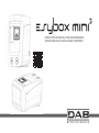
This manual refers to e.sybox mini³.
Read this documentation carefully before installation.
Installation and operation must comply with the local safety reg-
ulations in force in the country in which the product is installed.
Everything must be done in a workmanlike manner.
Failure to respect the safety regulations not only causes risk to
personal safety and damage to the equipment, but invalidates
every right to assistance under guarantee.
The products dealt with in this discussion fall within the type of
professional equipment and belong to insulation class 1.
Skilled personnel
The electrical and hydraulic connections may only be carried out
by skilled personnel in possession of the technical qualications
required by the safety regulations in force in the country in which
the product is installed.
The term skilled personnel means persons whose training, ex-
perience and instruction, as well as their knowledge of the re-
spective standards and requirements for accident prevention
and working conditions, have been approved by the person in
charge of plant safety, authorizing them to perform all the neces-
sary activities, during which they are able to recognize and avoid
all dangers. (Denition for technical personnel IEC 364).

ENGLISH
EN
42
RESPONSIBILITY
The Manufacturer does not vouch for correct operation of
the electropumps or answer for any damage that they may
cause if they have been tampered with, modied and/or run
outside the recommended work range or in contrast with
other indications given in this manual.
The Manufacturer declines all responsibility for possible er-
rors in this instructions manual, if due to misprints or errors
in copying. The Manufacturer reserves the right to make any
modications to products that it may consider necessary
or useful, without affecting their essential characteristics.
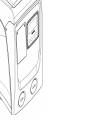
1- GENERAL
The product is an integrated system composed mainly of a self-priming
multi-stage centrifugal electropump, an electronic circuit that controls it
and an expansion vessel. Cooling of the motor with water rather than air
ensures less noise in the system and the possibility of locating it even in
recesses without ventilation.
Applications
Water systems supply and pressure boosting domestic use or industrial
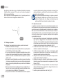
use. On the outside the product appears as a parallelepiped that presents
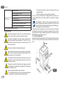
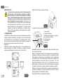
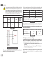
6 faces as shown in Fig.1.
Figure 1
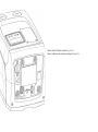
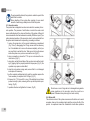
Face A: a door allows access to the Technical Compartment.
Inside the technical compartment you can access (see Fig.3):
1. Rapid Guide;
2. Technical data plate;
3. Filling cap (only for vertical
conguration);
4. Accessory tool;
5. Motor shaft;
6. QR-code
Face B: A rubber cable gland allows the exit of the power cable to be con-
nected to the power mains.
Face C: the 4 brass threads form the seat for the 4 support feet in the case
of vertical installation. The two 1” screw caps can be removed to make the
connections towards the system, depending on the installation congura-
tion you want to adopt. If applicable, connect to the connection marked
“IN” the system from which you want to draw water (well, cistern,…) and
connect the delivery system to the connection marked “OUT”. There is also
a ventilation grid. The 3/8” cap allows drainage of the system in the case of
horizontal installation. There is also a ventilation grid.
Face E: the 4 brass threads form the seat for the 4 support feet in the case
of horizontal installation. The main function of the 1” cap is drainage of the
system in the case of vertical installation. There are also 2 ventilation grids.
Figure 2
Figure 3
1
2
3
45
6
B
C
E
F
A

EN
ENGLISH
43
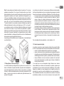
Face F: as indicated by the label to be removed, the 1” cap next to the
word “IN” on face C has a dual function: in the case of horizontal installa-
tion, the outlet that is closed by the cap acts as the system’s loading door
(see below “loading operations”, par. 2.2.3); in the case of vertical installa-
tion, the same outlet can act as the input hydraulic connection (exactly like
the one marked “IN” on face C and as an alternative to it). The other 1” cap
gives access to a second delivery connection that can be used at the same
time as or alternatively to the one indicated with “OUT” on face C. The user
interface panel is composed of a display and a keyboard and its function is
to set the system, query its status and communicate any alarms. The door
closed by 2 screws gives access to a special maintenance compartment:
cleaning of the non-return valve and resetting of the tank preload pressure.
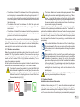
The system can be installed in 2 different congurations: horizontal (Fig.4)
or vertical (Fig.5).
1.1 Description of the Integrated Inverter
The electronic control integrated in the system is of the type with inverter
and it makes use of ow, pressure and temperature sensors, also inte-
grated in the system.
By means of these sensors the system switches on and off automatically
according to the utility’s needs and it is able to detect conditions of mal-
function, to prevent and indicate them.
Figure 5
Figure 4
The Inverter control ensures different functions, the most important of
which, for pumping systems, are the maintaining of a constant pressure
value in delivery and energy saving.
• The inverter is able to keep the pressure of a hydraulic circuit con-
stant by varying the rotation speed of the electropump. In operation
without an inverter the electropump is unable to modulate and, when
there is an increase of the request for ow, the pressure necessarily
decreases, or vice versa; this means the pressures are too high at
low ow rates or too low when there is an increased request for ow.
• By varying the rotation speed according to the instantaneous request
of the utility, the inverter limits the power supplied to the electropump
to the minimum necessary to ensure that the request is satised. In-
stead, operation without an inverter contemplates operation of the
electropump always and only at maximum power.
For the conguration of the parameters see chapters 4-5.
1.2 Integrated Expansion Vessel
The system is complete with an integrated expansion vessel with a total
capacity of 1 litres. The main functions of the expansion vessel are:
• to make the system elastic so as to protect it against water hammer;
• to ensure a water reserve which, in the case of small leaks, maintains
the pressure in the system for a longer time and spreads out needless
restarts of the system which otherwise would be continuous;
• when the utility is turned on, ensure the water pressure for the sec-
onds that the system takes to switch on and reach the correct rotation
speed.
It is not a function of the integrated expansion vessel to ensure a water re-
serve such as to reduce interventions of the system (requests from the util-
ity, not from a leak in the system). It is possible to add an expansion vessel
with the capacity you prefer to the system, connecting it to a point on the
delivery system (not a suction point!). In the case of horizontal installation
it is possible to connect to the unused delivery outlet. When choosing the
tank, consider that the quantity of water released will also depend on the
parameters SP and RP that can be set on the system (par. 4-5).

ENGLISH
EN
44
The expansion vessel is preloaded with pressurised air through the valve
accessible from the special maintenance compartment (Fig.1, Face F).
The preload value with which the expansion vessel is supplied by the man-
ufacturer is in agreement with the parameters SP and RP set as default,
and anyway it satises the following equation:
Pair = SP – RP – 0.7 bar Where:
- Pair = air pressure value in bar
- SP = Set Point (par. 5.3.1) in bar
- RP = Reduction of pressure to restart
(par. 5.5.1) in bar
So, by the manufacturer: Pair = 3.0 – 0.3 – 0.7 = 2.0 bar
If different values are set for the parameters SP and/or RP, regulate the
valve of the expansion vessel releasing or letting in air until the above
equation is satised again (e.g.: SP=2.0bar; RP=0.3bar; release air from
the expansion vessel until a pressure of 1.0 bar is reached on the valve).
Failure to respect the above equation may lead to malfunctions
of the system or to premature breakage of the diaphragm inside
the expansion vessel.
Considering the expansion vessel capacity of only 1 litres, any
operation to check the air pressure must be performed by con-
necting the pressure gauge very rapidly: on small volumes the
loss of even a limited quantity of air can cause an appreciable
drop in pressure. The quality of the expansion vessel ensures
the maintenance of the set air pressure value, proceed to check
it only at calibration or if you are sure of a malfunction.
Any operation to check and/or reset the air pressure must be
performed with the delivery system not under pressure: discon-
nect the pump from the power supply and open the utility nearest
to the pump, keeping it open until it no longer gives any water.
The special structure of the expansion vessel ensures its quan-
tity and duration over time, especially of the diaphragm which
is typically the component subject to wear for items of this type.
However, in the case of breakage, the entire expansion vessel
must be replaced and exclusively by authorised personnel.
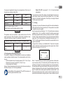
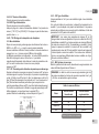
1.3 Technical characteristics
Topic
Parameter
e.sybox mini³
ELECTRIC
POWER SUPPLY
Voltage* 1x220-
240 V
1x230 V 1x110-
127 V
Frequency 50/60 Hz
Maximum power 850 W
Leakage current to
earth
<2 mA
STRUCTURAL
CHARACTERISTICS
Overall dimensions 445x262x242 mm without feet
support
Empty weight
(excluding packaging)
14 kg / 30,8 lb
Protection class
IP x4
Insulation class of the
motor
F
HYDRAULIC
PERFORMANCE
Maximum head 55 m / 180 ft
Maximum ow rate 80 l/min / 21 U.S. GPM
Priming
<5min at 8m / 26 ft
Maximum working
pressure
7.5 bar / 109 psi
WORKING
CONDITIONS
Max liquid temper-
ature
40 °C / 104 °F
Max environment
temperature
50 °C / 122 °F
Environment tempera-
ture of storage
-10÷60 °C / 14÷140 °F

EN
ENGLISH
45
FUNCTIONALITY AND
PROTECTIONS
Constant pressure
Protection against dry running
Antifreeze protection
Anticycling protection
Motor overload protection
Protection against abnormal supply voltages
Protection against excess temperature
*: refer to the technical plate on the pump
2- INSTALLATION
The system is designed for indoor use: do not install the system
outdoors and/or directly exposed to atmospheric agents.
The system is designed to be able to work in environments
where the temperature remains between 1°C and 50°C (on con-
dition that the electric power supply is ensured: see par. 5.6.8
“anti-freeze function”).
The system is suitable for treating drinking water.
The system cannot be used to pump salt water, sewage, inam-
mable, corrosive or explosive liquids (e.g. petroleum, petrol, thin-
ners), greases, oils or food productsi.
The system can suck up water with a level that does not exceed
the depth of 8 m (he height between the water level and the
pump suction mouth).
If the system is used for the domestic water supply, respect the
local regulations of the authorities responsible for the manage-
ment of water resources.
When choosing the installation site, check that:
• The voltage and frequency on the pump’s technical data plate
correspond to the values of the power supply system.
• The electrical connection is made in a dry place, far from any
possible ooding.
• The earth system must comply with the regulations.
If you are not sure of the absence of foreign bodies in the water to be
pumped, install a lter on the system intake that is suitable for catching
impurities.
The installation of a lter on intake causes a decrease of the
system’s hydraulic performance proportional to the loss of load
caused by the lter itself (generally the greater the ltering pow-
er, the greater the fall in performance).
Choose the type of conguration you intend to use (vertical or horizontal)
considering the connections to the system, the position of the user inter-
face panel, and the spaces available according to the indications below.
Wall installation is possible, see par. 8.2.
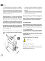
2.1 - Vertical Conguration
Screw the 4 rubber feet supplied loose in the package into the brass seats
in face C. Put the system in place, taking into account the dimensions in
Fig.6.
Figure 6

ENGLISH
EN
46
• The distance of at least 10mm between Face E of the system and any
wall is obligatory to ensure ventilation through the grids provided • I f
you expect to have to drain the system from its discharge door and
not from the system, leave a further distance sufcient to manoeuvre
the drainage cap.
• The distance of at least 10mm between Face B of the system and
an obstruction is obligatory to let out the power supply cable to the
mains socket.
• The distance of at least 200mm between Face A of the system and an
obstruction is recommended so as to be able to remove the door and
gain access to the technical compartment.
If the surface is not at, unscrew the foot that is not touching and adjust
its height until it contacts the surface so as to ensure the stability of the
system. The system must in fact be placed in a safe and stable position,
ensuring that its axis is vertical: it must not be in an inclined position.
2.1.1 Hydraulic connections
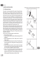
Make the connection at input to the system through the mouth on Face F
marked “IN” in Fig.6 (suction connection). Then remove the cap using a
screwdriver. Make the connection at output from the system through the
mouth on Face F marked “OUT” in Fig.6 (delivery connection). Then re-
move the cap using a screwdriver.
All the hydraulic connections of the system to the plant to which it can be
connected are of the threaded female type 1” GAS, made of brass.
If you intend to connect the product to the plant with ttings that
have a diameter larger than the normal 1” pipe (for example the
ring nut in the case of ttings in 3 pieces), make sure that the 1”
Gas male thread of the coupling protrudes at least 25mm from
the above diameter (see Fig.7).
Figure 7
< 25 mm
> 25 mm
The brass threads are housed in technopolymer seats. When
making the connection watertight by adding material (e.g. Teon,
hemp,...) ensure that the gasket is not too thick: under the action
of an adequate tightening torque (e.g. long handled pipe wrench),
the excess material could exert abnormal force on the technop-
olymer seat, damaging it irremediably.
With reference to its position with respect to the water to be pumped, the
installation of the system may be dened “above head” or “below head”. In
particular the installation is dened “above head” when the pump is placed
at a level higher than the water to be pumped (e.g. pump on the surface
and water in a well); vice versa it is “below head” when the pump is placed
at a level lower than the water to be pumped (e.g. overhead cistern and
pump below).
If the vertical installation of the system is of the “over head” type,
it is recommended to t a non-return valve in the suction section
of the system; this is to allow the operation of loading the system
(par. 2.1.2).
If the installation is of the “over head” type, install the suction pipe
from the water source to the pump in such a way as to avoid the
formation of goosenecks or siphons. Do not place the suction
pipe above the pump level (to avoid the formation of air bubbles
in the suction pipe). The suction pipe must draw at its entrance
at a depth of at least 30cm below the water level and must be
watertight along its whole length, as far as the entrance to the
electropump.
The suction and delivery pipes must be tted so that they do not
exert any mechanical pressure on the pump.
2.1.2.Loading Operation
Installation above head and below head
Installation “above head” (par. 2.1.1): access the technical compartment
and, using a screwdriver, remove the lling cap (Fig.3_point 6). Fill the
system with clean water through the loading door, taking care to let the air
out. If the non-return valve on the suction pipe (recommended in paragraph

EN
ENGLISH
47
2.1.1) has been placed close to the system entry door, the quantity of
water with which to ll the system should be 0,9 litres. It is recommended
to t the non-return valve at the end of the suction pipe (foot valve) so as
to be able to ll it quickly too during the loading operation. In this case the
quantity of water necessary for the loading operation will depend on the
length of the suction pipe (0,9 litres + …).
Installation “below head” (par. 2.1.1): if there are no check valves between
the water deposit and the system (or if they are open), it loads automati-
cally as soon as it is allowed to let out the trapped air. So slackening the
lling cap (Fig.3_point 6) enough to vent the trapped air allows the system
to load completely. You must survey the operation and close the loading
door as soon as the water comes out (however it is recommended to t a
check valve in the section of the suction pipe and to use it to control the
loading operation with the cap open). Alternatively, in the case where the
suction pipe is intercepted by a closed valve, the loading operation may be
carried out in a similar way to the one described for installation over head.
2.2 - Horizontal Conguration
Screw the 4 rubber feet supplied loose in the package into the brass seats
in face E. Put the system in place, taking into account the dimensions in
Fig.8.
Figure 8
• The distance of at least 10mm between Face B of the system and
an obstruction is obligatory to let out the power supply cable to the
mains socket.
• The distance of at least 200mm between Face A of the system and an
obstruction is recommended so as to be able to remove the door and
gain access to the technical compartment.
If the surface is not at, unscrew the foot that is not touching and adjust
its height until it contacts the surface so as to ensure the stability of the
system. The system must in fact be placed in a safe and stable position,
ensuring that its axis is vertical: it must not be in an inclined position.
2.2.1 Hydraulic connections
Make the connection at input to the system through the mouth on Face C
marked “IN” in Fig. 8 (suction connection). Then remove the cap using a screw-
driver. Make the connection at output from the system through the mouth on
Face C marked “OUT 1” in Fig. 8 and/or through the mouth on Face F marked
“OUT 2” in Fig. 8 (delivery connection).
In this conguration either of the 2 mouths can be used as an alternative to
the other (depending on the convenience of the installation), or simultaneously
(dual delivery system). Then remove the cap(s) from the door(s) you intend
to use with a screwdriver.
All the hydraulic connections of the system to the plant to which it can be con-
nected are of the threaded female type 1” GAS, made of brass.
See WARNING for Figure 7.
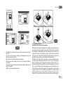
2.2.2 Orientation of the Interface Panel
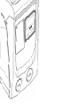
The Interface Panel has been designed so that it can be oriented in the
direction where it is most convenient for the user to read: its square shape
allows it to be rotated from 90° to 90° (Fig.9).

ENGLISH
EN
48
2.2.3 Loading Operation
Installation above head and below head
With reference to its position with respect to the water to be pumped, the instal-
lation of the system may be dened “above head” or “below head”. In particular
the installation is dened “above head” when the pump is placed at a level
higher than the water to be pumped (e.g. pump on the surface and water in a
well); vice versa it is “below head” when the pump is placed at a level lower than
the water to be pumped (e.g. overhead cistern and pump below).
Installation “above head”: with a screwdriver, remove the lling cap which,
for the horizontal conguration, is the one on Face F (Fig.1). Fill the system
with clean water through the loading door, taking care to let the air out: to en-
sure optimum lling it is convenient to open also the loading door on Face A
(Fig.1), used for lling in the vertical conguration, so as to let all the air out,
which otherwise could remain trapped in the system; take care to close the
openings correctly once the operation is completed. The quantity of water
with which to ll the system must be at least 0,7 litri almeno. litres. It is recom-
mended to t a non-return valve at the end of the suction pipe (foot valve) so
Figure 10
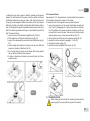
• Disengage the 4 screws at the corners of the panel using the acces-
sory tool.
• Do not remove the screws completely, just disengage them from the
thread on the product body.
• Be careful not to drop the screws into the system.
• Move the panel away, taking care not to pull on the signal transmis-
sion cable.
• Reposition the panel in its seat at the preferred angle taking care not
to pinch the cable.
• Tighten the 4 screws with the wrench.
Figure 9

EN
ENGLISH
49
as to be able to ll it quickly too during the loading operation. In this case the
quantity of water necessary for the loading operation will depend on the length
of the suction pipe (0,7 litres + …).
Installation “below head”: if there are no check valves between the water de-
posit and the system (or if they are open), it loads automatically as soon as it is
allowed to let out the trapped air. So slackening the lling cap (Face F - Fig.1)
enough to vent the air allows the system to load completely. You must survey
the operation and close the loading door as soon as the water comes out (how-
ever it is recommended to t a check valve in the section of the suction pipe
and to use it to control the loading operation with the cap loose). Alternatively,
in the case where the suction pipe is intercepted by a closed valve, the loading
operation may be carried out in a similar way to the one described for installa-
tion over head.
3 - COMMISSIONING
The suction depth must not exceed 8 m.
3.1 - Electrical Connections
To improve immunity to the possible noise radiated towards other appli-
ances it is recommended to use a separate electrical duct to supply the
product.
The line voltage may change when the electropump is started.
The line voltage may undergo variations depending on other de-
vices connected to it and on the quality of the line.
It is recommended to carry out installation as indicated in the
manual, in compliance with the laws, directives and standards in
force in the place of use and depending on the application. The
product contains an inverter inside which there are continuous
voltages and currents with high-frequency components (see ta-
ble 0).
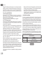
Type of possible fault currents to earth
Alternating
Unipolar
pulsed
Direct
With high-
frequency
components
Inverter with
single-phase
power supply
X X X
The thermal magnetic circuit breaker must be correctly sized (see Electri-
cal Characteristics).
Table 0
Figure 11 - bis Installation example

ENGLISH
EN
50
For pumps not supplied with a plug, the correspondence of the colours of
the leads is as indicated in table 0bis:
Connection Type A Type B
Phase Brown Brown
Neutral Blue Blue
Earth (EP) Yellow/Green Green
Type A: European markets or similar.
Type B: American and Canadian markets or similar.
The appliance must be connected to a main switch that cuts off all the
power supply poles. When the switch is in off position, the distance sepa-
rating each contact must respect the indications in table 0tris.
Minimum distance between the contacts of the power switch
Power supply [V] ≤127 >127 e ≤240
Minimum distance
[mm]
>1,7 >3
3.2 Conguration of the Integrated Inverter
The system is congured by the manufacturer to satisfy most installation
cases operating at constant pressure. The main parameters set in the fac-
tory are:
• Set-Point (desired value of constant pressure); SP = 2.7 bar / 39 psi.
• Reduction of pressure to restart RP = 0.3 bar / 4.3 psi.
• Anti-cycling function: Disabled.
However, these parameters and others can be set by the user according to
the system. See par. 5-6-7 for the specications.
For the denition of the parameters SP and RP, the pressure at
which the system starts has the value:
Table 0 bis
Table 0 tris
Pstart = SP – RP For example: 2.7 – 0.3 = 2.4 bar in the default
conguration
The system does not work if the utility is at a height higher than the equiva-
lent in metres of water column of the Pstart (consider 1 bar = 10 m water
column): for the default conguration, if the utility is at a height of at least
27m the system does not start.
3.3 - Priming
The priming of a pump is the phase during which the machine attempts to
ll the body and the suction pipe with water. If the operation is successful
the machine can work regularly.
Once the pump has been lled (par. 2.1.2, 2.2.3) and the device has been
congured (par. 3.2), it is possible to connect the electric power supply
after having opened at least one utility on delivery for the rst 10 seconds.
If a ow of water is detected in delivery, the pump is primed and starts its
regular work. This is the typical case of installation below head (par. 2.1.2,
2.2.3). The utility opened in delivery from which the pumped water is com-
ing out can be closed.
If a regular ow in delivery is not detected after 10 seconds, the system
asks for conrmation to enter the priming procedure (typical case of instal-
lation above head pa 2.1.2, 2.2.3). Or:
When “+” is pressed the pump enters the priming procedure: it starts work-
ing for a maximum time of 5 minutes during which the safety block for dry
operation is not tripped. The priming time depends on various parameters,
the most inuential of which are the depth of the water level from which it is
drawing, the diameter of the suction pipe, the water-tightness of the suction
pipe. On condition that a suction pipe is used that is no smaller than 1” and
that it is well sealed (with no holes or joins from which it can take in air), the
product has been studied to manage to prime in water conditions up to 8m

EN
ENGLISH
51
in depth in a time of less than 5 minutes. As soon as the product detects
a regular ow in delivery, it leaves the priming procedure and starts its
regular work. The utility opened in delivery from which the pumped water
is coming out can be closed. If after 5 minutes of the procedure the product
is still not primed, the interface display sends a failure message. Discon-
nect the power supply, load the product adding new water, wait 10 minutes
and repeat the procedure from the moment you put the plug in the socket.
Press “-“ to conrm that you do not want to start the priming procedure.
The product remains in alarm status
Operation
Once the electropump is primed, the system starts regular operation ac-
cording to the congured parameters: it starts automatically when the tap
is turned on, supplies water at the set pressure (SP), keeps the pressure
constant even when other taps are turned on, stops automatically after
time T2 once the switching off conditions are reached (T2 can be set by
the user, factory value 10 sec).
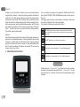
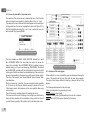
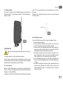
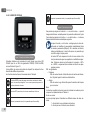
4 - THE KEYPAD AND THE DISPLAY
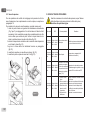
Figure 12: Aspect of the user interface
The user interface is composed of a keypad with 128x240 pixel LCD dis-
play and with POWER, COMM, ALARM warning leds as can be seen in
Figure 12.
The display shows the values and the statuses of the device, with indica-
tions on the functionality of the various parameters.
The functions of the keys are summed up in Table 1.
The MODE key allows you to move on to the next items in the same
menu. Holding it down for at least 1 sec allows you to skip to previous
menu item.
The SET key allows you to leave the current menu.
Decreases the current parameter (if it is an editable parameter).
Increases the current parameter (if it is an editable parameter).
Holding down the “+” key or the “-” key allows the automatic increase/
decrease of the parameter selected. After the “+” key or the “-” key has
been held down for 3 seconds, the automatic increase/decrease speed
increases.
Table 1: Key functions

ENGLISH
EN
52
When the + key or the - key is pressed the selected value is
modied and saved immediately in the permanent memory (EE-
prom). If the machine is switched off, even accidentally, in this
phase it does not cause the loss of the parameter that has just
been set.
The SET key is only for leaving the current menu and is not nec-
essary for saving the changes made. Only in particular cases
described in the following paragraphs are some values updated
by pressing “SET” or “MODE”.
Warning leds
• Power
White led. Lit with a xed light when the machine is powered. Blink-
ing when the machine is disabled.
• Alarm
Red led. Lit with a xed light when the machine is blocked by an
error.
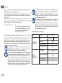
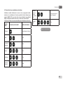
Menus
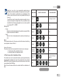
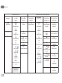
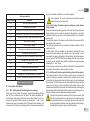
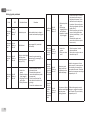
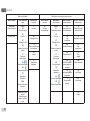
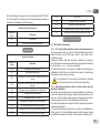
The complete structure of all the menus and of all the items of which they
are composed is shown in Table 3.
Access to the menus
The various menus can be accessed from the main menu in two ways:
1 - Direct access with a combination of keys.
2 - Access by name with a drop-down menu.
4.1 Direct Access with a Combination of Keys
The desired menu can be accessed directly by pressing simultaneously
the appropriate combination of keys for the required time (for example
MODE SET to enter the Setpoint menu) and the various items in the menu
are scrolled with the MODE key.
Table 2 shows the menus that can be reached with the combinations of
keys.
MENU NAME DIRECT ACCESS KEYS HOLD-DOWN TIME
User On releasing the button
Monitor 2 Sec
Setpoint 2 Sec
Manual 5 Sec
Installer 5 Sec
Technical
assistance
5 Sec
Reset factory
values
2 sec after switching on
appliance
Reset 2 Sec
Table 2: Access to the menus

EN
ENGLISH
53
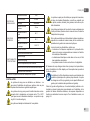
Reduced menu (visible) Extended menu (direct access or password)
Main Menu
User Menu
mode
Monitor Menu
set-minus
Setpoint Menu
mode-set
Manual Menu
set-minus-plus
Installer Menu
mode-set-minus
Tech. Assist. Menu
mode-set-plus
MAIN
(Main Page)
STATUS
RS
Revs per minute
VP
Pressure
VF
Display of ow
PO
Power absorbed by
pump
C1
Pump phase current
SV
Supply voltage
SR
Supply range
TE
Dissipator
temperature
PKm
Pressure measured at
intake
CT
Contrast
SP
Setpoint pressure
STATUS
RI
Speed setting
VP
Pressure
VF
Display of ow
PO
Power absorbed by
pump
C1
Pump phase current
RS
Revs per minute
TE
Dissipator
temperature
SV
Supply voltage
SR
Supply range
RP
Decrease pressure
for restart
TB
Block time for
water lack.
Menu Selection BK
Back lighting
OD
Type of
plant
T2
Delay in switching off
TK
Backlighting switch-
on time
MS
Measuring system
GP
Proportional gain.
LA
Language
AS
Wireless Devices
GI
Integral gain
TE
Dissipator temperature
EK
Enabling
low pressure function
on suction
RM
Maximum speed
PK
Low pressure threshold
on suction
AY
Anti Cycling
T1
Low pr. delay
AE
Anti-blocking
Hours switched on
Working hours
Number of starts
AF
AntiFreeze

ENGLISH
EN
54
PI
Power histogram
RF
Reset faults and
warnings
Output ow meter PW
Modify Password
VE
Information
HW e SW
FF
Fault & Warning
(Log)
Key
Parameters available in version K.
Parameters available only in version DV
Table 3: Menu structure

EN
ENGLISH
55
4.2 - Access by name with a drop-down menu
The selection of the various menus is accessed by name. From the main
menu you access menu selection by pressing either of the + or – keys.
The names of the menus that can be accessed appear on the menu selec-
tion page and one of the menus is highlighted by a bar (see Figure 13-14).
Shift the highlighting bar using the + and – keys to select the menu you
want and enter it by pressing MODE.
The items available are MAIN, USER, MONITOR, followed by a fourth
item, EXTENDED MENU; this item allows the number of menus dis-
played to be extended. When EXTENDED MENU is selected a pop-up
appears asking you to type in an access key (PASSWORD). The access
key (PASSWORD) coincides with the combination of keys used for direct
access (as in Table 8) and allows the extended display of the menus from
the menu corresponding to the access key to all those with a lower priority.
The order of the menus is: User, Manual Setpoint, Manual, Installer, Tech-
nical Assistance.
When an access key is selected, the menus released remain available
for 15 minutes or until they are disabled manually by means of the item
“Hide forward menus” which appears on the menu selection when using
an access key.
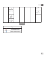
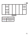
Figure 14 shows an operating diagram for selecting the menus.
The menus are in the centre of the page, from the right you reach them by
means of direct selection with a combination of keys, while from the left
you reach them by means of the selection system with drop-down menu.
Figure 13: Selection of the drop-down menus
4.3 - Structure of the menu pages
When switched on, some presentation pages are displayed showing the
name of the product and the logo, after which the main menu appears.
The name of each menu, whichever it may be, is always at the top of the
display.
The following always appear on the main page
Status: operating status (e.g. standby, go, Fault)
Revs per minute: value in [rpm]
Pressure: value in [bar] or [psi] depending on the set unit of measure.
Power: value in [kW] of the power absorbed by the device.
Figure 14: Diagram of possible menu accesses
La page est en cours de chargement...
La page est en cours de chargement...
La page est en cours de chargement...
La page est en cours de chargement...
La page est en cours de chargement...
La page est en cours de chargement...
La page est en cours de chargement...
La page est en cours de chargement...
La page est en cours de chargement...
La page est en cours de chargement...
La page est en cours de chargement...
La page est en cours de chargement...
La page est en cours de chargement...
La page est en cours de chargement...
La page est en cours de chargement...
La page est en cours de chargement...
La page est en cours de chargement...
La page est en cours de chargement...
La page est en cours de chargement...
La page est en cours de chargement...
La page est en cours de chargement...
La page est en cours de chargement...
La page est en cours de chargement...
La page est en cours de chargement...
La page est en cours de chargement...
La page est en cours de chargement...
La page est en cours de chargement...
La page est en cours de chargement...
La page est en cours de chargement...
La page est en cours de chargement...
La page est en cours de chargement...
La page est en cours de chargement...
La page est en cours de chargement...
La page est en cours de chargement...
La page est en cours de chargement...
La page est en cours de chargement...
La page est en cours de chargement...
La page est en cours de chargement...
La page est en cours de chargement...
La page est en cours de chargement...
La page est en cours de chargement...
La page est en cours de chargement...
La page est en cours de chargement...
La page est en cours de chargement...
La page est en cours de chargement...
La page est en cours de chargement...
La page est en cours de chargement...
La page est en cours de chargement...
La page est en cours de chargement...
La page est en cours de chargement...
La page est en cours de chargement...
La page est en cours de chargement...
La page est en cours de chargement...
La page est en cours de chargement...
La page est en cours de chargement...
-
 1
1
-
 2
2
-
 3
3
-
 4
4
-
 5
5
-
 6
6
-
 7
7
-
 8
8
-
 9
9
-
 10
10
-
 11
11
-
 12
12
-
 13
13
-
 14
14
-
 15
15
-
 16
16
-
 17
17
-
 18
18
-
 19
19
-
 20
20
-
 21
21
-
 22
22
-
 23
23
-
 24
24
-
 25
25
-
 26
26
-
 27
27
-
 28
28
-
 29
29
-
 30
30
-
 31
31
-
 32
32
-
 33
33
-
 34
34
-
 35
35
-
 36
36
-
 37
37
-
 38
38
-
 39
39
-
 40
40
-
 41
41
-
 42
42
-
 43
43
-
 44
44
-
 45
45
-
 46
46
-
 47
47
-
 48
48
-
 49
49
-
 50
50
-
 51
51
-
 52
52
-
 53
53
-
 54
54
-
 55
55
-
 56
56
-
 57
57
-
 58
58
-
 59
59
-
 60
60
-
 61
61
-
 62
62
-
 63
63
-
 64
64
-
 65
65
-
 66
66
-
 67
67
-
 68
68
-
 69
69
-
 70
70
-
 71
71
-
 72
72
-
 73
73
-
 74
74
-
 75
75


DAB E.SYBOX MINI 3 Manuel utilisateur
- Taper
- Manuel utilisateur
- Ce manuel convient également à
dans d''autres langues
- English: DAB E.SYBOX MINI 3 User manual
Documents connexes
-
DAB ESYBOX MINI 3 Manuel utilisateur
-
-
-
-
-
DAB ESYBOX Mode d'emploi
-
-
-
DAB DTron 3 Mode d'emploi
-
DAB 2 EURO AD Mode d'emploi
