
ISTRUZIONI PER L'INSTALLAZIONE E LA MANUTENZIONE (IT)
INSTRUCTIONS FOR INSTALLATION AND MAINTENANCE (GB)
INSTRUCTIONS POUR L´INSTALLATION ET LA MAINTENANCE (FR)
INSTALLATIONS- UND WARTUNGSANLEITUNGEN (DE)
INSTRUCCIONES DE INSTALACIÓN Y MANTENIMIENTO (ES)
INSTRUCTIES VOOR INSTALLATIE EN ONDERHOUD (NL)
ИНСТРУКЦИЯ ПО МОНТАЖУ И ТЕХНИЧЕСКОМУ ОБСЛУЖИВАНИЮ (RU)
POKYNY K INSTALACI A ÚDRŽBĚ (CZ)
INSTRUKCJA MONTAŻU I KONSERWACJI (PL)
INSTRUÇÕES PARA A INSTALAÇÃO E A MANUTENÇÃO (PT)
ASENNUS- JA HUOLTO-OHJEET (FI)
INSTALLATIONS- OCH UNDERHÅLLSANVISNING (SE)
INSTRUCŢIUNI PENTRU INSTALARE ŞI ÎNTREŢINERE (RO)
ΟΔΗΓΙΕΣ ΓΙΑ ΤΗΝ ΕΓΚΑΤΑΣΤΑΣΗ ΚΑΙ ΤΗ ΣΥΝΤΗΡΗΣΗ (GR)
KURULUM VE BAKIM TALIMATLARI (TR)
INSTALLÁCIÓS ÉS KARBANTARTÁSI KÉZIKÖNYV (HU)
ИНСТРУКЦИЯ ЗА МОНТИРАНЕ И ПОДДРЪЖКАТА (BG)
ﺔﻧﺎﯿﺼﻟاو ﺐﯿﻛﺮﺘﻟا تﺎﻤﯿﻠﻌﺗ)ﺔّﯿِﺑَﺮَﻌﻟا ﺔﻐﻠﻟا(

ENGLISH
41
INDEX
1. GENERAL ................................................................................................................................................................................... 42
1.1 Applications .............................................................................................................................................................................. 42
1.2 Integrated electropump ........................................................................................................................................................... 42
1.3 Integrated Inverter .................................................................................................................................................................... 43
1.4 Integrated Expansion Vessel .................................................................................................................................................. 43
1.5 Technical characteristics ........................................................................................................................................................ 43
2. PUMPABLE LIQUIDS ................................................................................................................................................................. 44
3. INSTALLATION........................................................................................................................................................................... 44
4. PROCEDURE FOR FIXING THE PUMP TO THE ESYDOCK BASE ......................................................................................... 45
5. HYDRAULIC CONNECTIONS .................................................................................................................................................... 47
5.1 Loading Operation – Installation above head and below head ............................................................................................ 47
5.2 Maximum pressure at intake (pump below head) ................................................................................................................. 48
5.3 Systems in booster mode ........................................................................................................................................................ 48
6. COMMISSIONING ....................................................................................................................................................................... 49
6.1 Electrical Connections ............................................................................................................................................................. 49
6.2 Configuration of the Integrated Inverter ................................................................................................................................ 50
6.3 Priming ...................................................................................................................................................................................... 50
7. THE KEYPAD AND THE DISPLAY ............................................................................................................................................ 51
7.1 Direct access with a combination of keys ............................................................................................................................. 52
7.2 Access by name with a drop-down menu .............................................................................................................................. 53
7.3 Structure of the menu pages ................................................................................................................................................... 54
7.4 Blocking parameter setting by Password .............................................................................................................................. 55
7.5 Enabling and disabling the motor .......................................................................................................................................... 55
8. MEANING OF THE INDIVIDUAL PARAMETERS ...................................................................................................................... 55
8.1 User Menu ................................................................................................................................................................................. 55
8.2 Monitor Menu ............................................................................................................................................................................ 57
8.3 Setpoint Menu ........................................................................................................................................................................... 57
8.4 Manual Menu ............................................................................................................................................................................. 58
8.5 Installer Menu ........................................................................................................................................................................... 59
8.6 Technical Assistance Menu .................................................................................................................................................... 61
9. RESET AND FACTORY SETTINGS ........................................................................................................................................... 67
9.1 General system reset ............................................................................................................................................................... 67
9.2 Factory settings ........................................................................................................................................................................ 67
9.3 Restoring the factory settings ................................................................................................................................................ 67
10. PROTECTION SYSTEMS ........................................................................................................................................................... 68
10.1 Description of blockages ....................................................................................................................................................... 69
10.2 Manual reset of error conditions .......................................................................................................................................... 69
10.3 Self-reset of error conditions ................................................................................................................................................ 69
11. PARTICULAR INSTALLATIONS ................................................................................................................................................ 70
11.1 Multiple Sets ........................................................................................................................................................................... 70
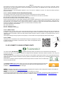
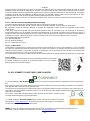
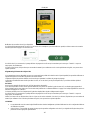
12. APP, DCONNECT CLOUD AND SOFTWARE UPDATE ........................................................................................................... 73
12.1 System requirements ............................................................................................................................................................. 74
12.2 Updating the software ............................................................................................................................................................ 74
12.3 DSYNC ..................................................................................................................................................................................... 76
13. MAINTENANCE .......................................................................................................................................................................... 77
13.1 Accessory tool ........................................................................................................................................................................ 77
13.2 Emptying the system ............................................................................................................................................................. 77
13.3 Non-return valve ..................................................................................................................................................................... 77
13.4 Motor shaft .............................................................................................................................................................................. 78
13.5 Expansion Vessel ................................................................................................................................................................... 78
14. TROUBLESHOOTING ................................................................................................................................................................ 79

ENGLISH
42
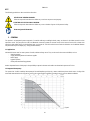
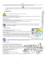
KEY
The following symbols have been used in the discussion:
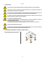
SITUATION OF GENERAL DANGER.
Failure to respect the instructions that follow may cause harm to persons and property.
SITUATION OF ELECTRIC SHOCK HAZARD.
Failure to respect the instructions that follow may cause a situation of grave risk for personal safety.
Notes and general information.
1. GENERAL
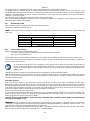
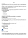
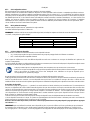
The product is an integrated system composed of a vertical multi-stage centrifugal electric pump, an electronic circuit that controls it and an
expansion vessel. The pump also has WiFi and Bluetooth connection systems for remote control via DConnect Cloud and for a better user
experience with mobile devices via the dedicated app, see chapter 12. The APP and DConnect Cloud also allow the use of additional features
not present directly on the display (e.g. energy and flow meters).
1.1 Applications
Indicated for booster sets for water systems of small, medium and large users. They can be used in the most varied fields, such as:
- Washing systems
- Supply of drinking water and autoclave supplies
- Boiler supply
- Irrigation systems
- Other pressure boosting systems
Another important feature of this pump is the possibility to operate in booster mode with a maximum intake pressure of 5.0 bar.
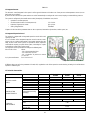
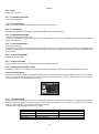
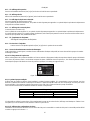
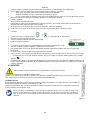
1.2 Integrated electropump
The system has a built-in centrifugal electropump of the multi-impeller type driven by a water-cooled three-phase electric motor. Cooling of the
motor with water rather than air ensures less noise in the system and the possibility of locating it even in recesses without ventilation.
Figure 1

ENGLISH
43
1.3 Integrated Inverter
The electronic control integrated in the system is of the type with inverter and it makes use of two pressure and temperature sensors (one on
intake and one on delivery).
By means of these sensors the system switches on and off automatically according to the user’s needs, keeping a constant delivery pressure.
The system is configured by the manufacturer to satisfy the majority of installation cases, that is:
• Operation at constant pressure;
• Set-Point (desired value of constant pressure): SP = 3.0 bar
• Reduction of pressure to restart: RP = 0.3 bar
• Anti-cycling function: Disabled
Chapters 8-9-10 show all the parameters that can be set: pressure, intervention of protections, rotation speed, etc.
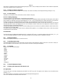
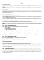
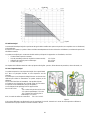
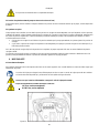
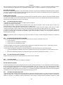
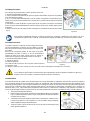
1.4 Integrated Expansion Vessel
The system is complete with an integrated expansion vessel with a total
capacity of 2 litres.
It is not a function of the integrated expansion vessel to ensure a water
reserve such as to reduce interventions of the system (requests from the
utility, not from a leak in the system). It is possible to add an expansion
vessel with the capacity you prefer to the system, connecting it to a point
on the delivery system (not a suction point!).
The expansion vessel is preloaded according to the following ratio:
Pair= SP-RP-0.2 bar Where:
- Pair = air pressure value in bar
- SP = Set Point (7.3) in bar
- RP = Reduction of pressure to restart
(7.5.1) in bar
So, by the manufacturer: Pair = 3-0.2-0.3=2.5
Figure 2
If different values are set for the parameters SP and/or RP, regulate the valve of the expansion vessel releasing or letting in air until the above
equation is satisfied again.
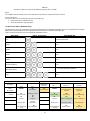
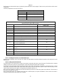
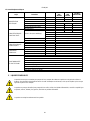
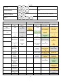
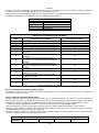
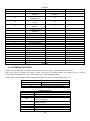
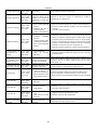
1.5 Technical characteristics
Text Parameter
ESYBOX MAX
60/120M
ESYBOX MAX
60/120T
ESYBOX MAX
85/120T
ELECTRIC POWER
SUPPLY
Voltage
208-240
380/480
380/480
Phases
1
3
3
Frequency
50/60
Maximum current
11,8 A
4,2 A
5,5 A
Maximum power
2,68 KW
2,65 KW
3,5 KW
Leakage current to earth
<2 mA
<4 mA
<4 mA
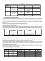
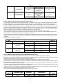
CONSTRUCTION
CHARACTERISTICS
Overall dimensions
766x375x384
Empty weight (excluding
packaging)
PUMP
29
29
30
ESYDOCK
9
2 ESYDOCK
18
3 ESYDOCK
27
Protection class
IPX5
Motor insulation class
F
HYDRAULIC
PERFORMANCE
Maximum head
7,7bar
7,7bar
10bar
Maximum pressure at
intake
5 bar
Maximum working
pressure (PN)
12 bar
Maximum flow rate
300 l/min

ENGLISH
44
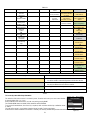
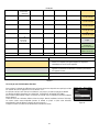
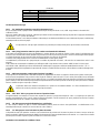
WORKING
CONDITIONS
Max liquid temperature
50°C ( 40°C – AMERICAS )
Max environment
temperature
55°C ( 45°C – AMERICAS )
Storage environment
temperature
-10÷60 °C
FUNCTIONALITY AND
PROTECTIONS
Constant pressure
Wireless communication
WiFi and Bluetooth communication (APP and DConnect Cloud)
Protection against dry running
Antifreeze protection
Anticycling protection
Motor overload protection
Protection against abnormal supply voltages
Protection against excess temperature
Table 1
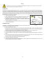
2. PUMPABLE LIQUIDS
The machine has been designed and made for pumping water, free from explosive substances and solid particles or fibres, with a
density of 1000 Kg/m³, a kinematic viscosity of 1mm²/s and non chemically aggressive liquids.
The system cannot be used to pump salt water, sewage, inflammable, corrosive or explosive liquids (e.g. petroleum, petrol,
thinners), greases, oils or food products.
The system is suitable for treating drinking water.
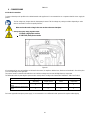
3. INSTALLATION
The pumps may contain small quantities of residual water from testing
The electric pump has degree of protection IPX5 and can be installed in dusty environments without special
weather protection measures.
The system is designed to be able to work in environments where the temperature remains between 0°C and 55°C (on
condition that the electric power supply is ensured: see par. 8.6.14 “anti-freeze function”).
If the system is used for the domestic water supply, respect the local regulations of the authorities responsible for
the management of water resources.
When choosing the installation site, check that:
• The voltage and frequency on the pump’s technical data plate correspond to the values of the power supply
system.
• The electrical connection is made in a dry place, far from any possible flooding.
• The electrical system is provided with a differential switch with
I Δn ≤ 30 mA and that the earth system is efficient.
The pump must be installed in vertical position.

ENGLISH
45
The pump is not self-priming. It is suitable for suction from tanks or connected to the mains in booster mode where it is
possible according to local regulations.
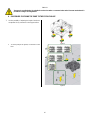
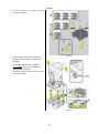
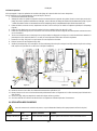
4. PROCEDURE FOR FIXING THE PUMP TO THE ESYDOCK BASE
1. Use the possibility of adjusting the height of the feet to
compensate for any unevenness in the support surface.
Figure 3
2. To fix the pump to the ground, use the slots on the
base.
Figure 4

ENGLISH
46
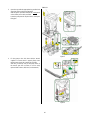
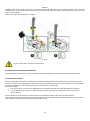
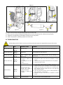
3. Open the caps with the appropriate key provided and
store them in the technical compartment.
With the grease provided, lubricate the O-Ring seals
on the delivery and suction manifolds.
Lower the pump onto the Esydock base, centring the
fixing pins.
Figure 5
4. Fix the pump to the dock base with the wrench
supplied. To ensure that it is properly fixed, check
that the green ring of the centring pins is visible.
After use, put the key away on the pump hooks. If
the wrench gets lost or broken, it can be easily
replaced with a 10mm (13/32 inch) socket wrench).
Figure 6

ENGLISH
47
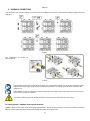
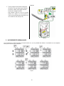
5. HYDRAULIC CONNECTIONS
The connections to the hydraulic system are all 2" female, with the possibility to be reduced to 1"1/4 female with adapters supplied only for the
single dock.
Figure 7
Four configurations are possible, as
shown in figure 8.
Figure 8
If the installation of the system is of the “above head” type, it is recommended to provide a non-return valve as foot valve (at the
beginning of the suction pipe); this will allow the system loading operation so as to fill the whole pipe before switching on the
pump (par. 5.1)
If the installation is of the “over head” type, install the suction pipe from the water source to the pump in such a way as to avoid
the formation of goosenecks or siphons.
The suction and delivery pipes must be fitted so that they do not exert any mechanical pressure on the pump.
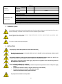
5.1 Loading Operation – Installation above head and below head
Installation “above head” (Fig 9A): access the technical compartment and, with the aid of the accessory tool or with a screwdriver, remove the
filling cap. Fill the system with clean water through the loading door, taking care to let the air out.

ENGLISH
48
Installation “below head” (Fig 9B): if there are no check valves between the water deposit and the system (or if they are open), it loads
automatically as soon as it is allowed to let out the trapped air. So slackening the filling cap enough to vent the trapped air (2.5 turns) allows the
system to load completely.
Tighten the cap again when the operation is complete.
Figure 9
Dry up any water residue in the technical compartment.
5.2 Maximum pressure at intake (pump below head)
It is important that the intake pressure is always lower than the maximum working pressure allowed by the pump as indicated in the table.
5.3 Systems in booster mode
Each pump, depending on the model, is characterised by a maximum achievable Setpoint pressure (without the suction being pressurised).
The user is allowed to set any setpoint pressure (SP) from 1.0 bar up to the maximum pressure PN, thus reaching pressure values higher than
the maximum pressure that can be achieved by the pump in order to allow use in booster mode.
Operation is as follows:
• If the set pressure SP is lower than the maximum pressure achievable by the pump, the system will adjust to the set pressure;
• If, on the other hand, the set pressure is greater than that achievable by the pump, the set point will be reached only if there is
pressure at intake.
Based on the setpoint set and the pressure read at intake, the pump understands whether it will achieve the desired setpoint.
If the setpoint set cannot be reached due to the reduced intake pressure, the pump will still continue to deliver water at the pressure it is able to
achieve and will show the flashing pressure gauge symbol on the main page.

ENGLISH
49
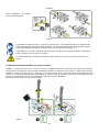
6. COMMISSIONING
6.1 Electrical Connections
To improve immunity to the possible noise radiated towards other appliances it is recommended to use a separate electrical duct to supply the
product.
The line voltage may change when the electropump is started. The line voltage may undergo variations depending on other
devices connected to it and on the quality of the line.
Make sure that the mains voltage is the same as that on the motor data plate.
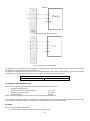
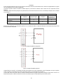
Strictly observe the wiring diagrams below:
- L-N-Earth, single-phase version
- U-V-W-Earth, three-phase version
Figure 10
It is recommended to carry out installation as indicated in the manual, in compliance with the laws, directives and standards in force in the place
of use and depending on the application.
The product contains an inverter inside which there are continuous voltages and currents with high-frequency components.
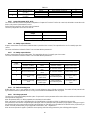
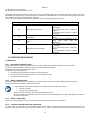
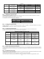
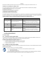
The differential switch for protecting the system must be correctly sized according to the characteristics indicated in Table 2 and Table 3.
Type of possible fault currents to earth
Alternating Unipolar pulsed Direct
With high-frequency
components
Inverter with single-phase power
supply
Inverter with three-phase power
supply
Table 2
For inverter types with three-phase power supply, it is recommended to use a differential switch protected also against sudden tripping.

ENGLISH
50
Fig 11 example of single-phase installation
Fig 12 example of three-phase installation
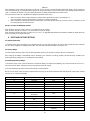
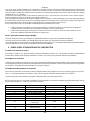
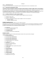
The appliance must be connected to a main switch that cuts off all the power supply poles. When the switch is in off position, the distance
separating each contact must respect the indications in table 3.
The cable gland, supplied with the terminal box, binds the outer diameter of the cable sheath in a range between 7 and 13mm. The mammoth
terminal block can accommodate cables with a lead cross-section up to 2.5mm2 (AWG14 for USA versions).
Minimum distance between the contacts of the power switch
Minimum distance [mm]
>3
Table 3
6.2 Configuration of the Integrated Inverter
The system is configured by the manufacturer to satisfy the majority of installation cases, that is:
• operation at constant pressure;
• Set-Point (desired value of constant pressure): SP = 3.0 bar
• Reduction of pressure to restart: RP = 0.3 bar
• Anti-cycling function: Disabled
However, all these parameters can be set by the user (see the chapter Settable parameters)
The system does not work if the utility is at a height higher than the equivalent in metres of water column of the Pstart (consider 1 bar = 10 m.
water column): for the default configuration, if the utility is at a height of at least 27m the system does not start.
6.3 Priming
For the first start-up, follow the steps below:
• Make the hydraulic and electrical connections (without supplying power)

ENGLISH
51
• Fill the pump (par 5.1)
• Open a utility on delivery
• Provide electric power supply
• Connect to the pump via App to carry out assisted configuration
The system starts and checks the presence of water in delivery. If a regular flow of water is detected, the pump is primed and starts its pressure
boosting work.
Operation
Once the electropump is primed, the system starts regular operation according to the configured parameters: it starts automatically when the tap
is turned on, supplies water at the set pressure (SP), keeps the pressure constant even when other taps are turned on, stops automatically after
time T2 once the switching off conditions are reached (T2 can be set by the user, factory value 10 sec).
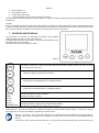
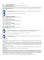
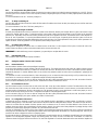
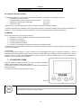
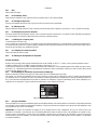
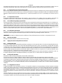
7. THE KEYPAD AND THE DISPLAY
The user interface is composed of a keypad with 2.8’’ display and with POWER,
COMM, ALARM warning leds as can be seen in Figure 13.
The display shows the values and the statuses of the device, with indications on the
functionality of the various parameters.
The functions of the keys are summed up in Table 4.
Figure 13
The MODE key allows you to move on to the next items in the same menu. Holding it down for at least 1 sec allows
you to skip to previous menu item.
The SET key allows you to leave the current menu.
Decreases the current parameter (if it is an editable parameter).
Increases the current parameter (if it is an editable parameter).
WHITE LED
POWER On with a fixed light: the machine is powered
Flashing: the machine is disabled
RED LED
ALLARM
On with a fixed light: the machine is blocked by an error
BLUE LED
COMMUNICATION
On with a fixed light: active wireless communication
Slow flashing: wireless communication not available due to problems
Fast flashing: association with other wireless devices in progress
Table 4
Holding down the “^” key or the “˅” key allows the automatic increase/decrease of the parameter selected. After the “^” key or the “˅” key has
been held down for 3 seconds, the automatic increase/decrease speed increases.
When the ^ key or the ˅ key is pressed the selected value is modified and saved immediately in the permanent memory
(EEprom). If the machine is switched off, even accidentally, in this phase it does not cause the loss of the parameter that has just
been set.
The SET key is only for leaving the current menu and is not necessary for saving the changes made. Only in particular cases

ENGLISH
52
described in chapter 0 are some values updated by pressing “SET” or “MODE”.
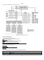
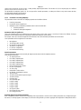
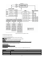
Menus
The complete structure of all the menus and of all the items of which they are composed is shown in Table 6.
Access to the menus
The various menus can be accessed from the main menu in two ways:
1. Direct access with a combination of keys
2. Access by name with a drop-down menu
7.1 Direct access with a combination of keys
The desired menu can be accessed directly by pressing simultaneously the appropriate combination of keys for the required time (for example
MODE SET to enter the Setpoint menu) and the various items in the menu are scrolled with the MODE key.
Table 5 shows the menus that can be reached with the combinations of keys.
MENU NAME
DIRECT ACCESS KEYS
HOLD-DOWN TIME
User
On releasing the button
Monitor
2 Sec
Setpoint
2 Sec
Manual
5 Sec
Installer
5 Sec
Technical assistance
5 Sec
Reset factory values
2 sec after switching on appliance
Reset
2 Sec
Table 5
Reduced menu (visible)
Extended menu (direct access or password)
Main Menu
User Menu
mode
Monitor Menu
set- ˅
Setpoint Menu
mode-set Manual Menu
set- ˅ - ^ Installer Menu
mode-set- ˅ Tech. Assist. Menu
mode-set-^
MAIN
(Main Page) STATUS
BK
Back lighting SP
Setpoint pressure STATUS
RP
Decrease pressure
for restart
TB
Block time for
water lack
Menu
Selection RS
Revs per minute
TK
Backlighting switch-
on
time
RI
Speed setting OD
Type of plant T1
Low pressure delay
VP
Pressure
LA
Language
VP
Pressure
AD
Address Configuration
T2
Delay in switching off
VF
Display of flow
TE
Heat sink
temperature
VF
Display of flow MS
Measuring system GP
Proportional gain
PO
Power absorbed by
pump
BT
Card temperature
PO
Power delivered to
the pump
AS
Wireless devices GI
Integral gain
C1
C1
PR
RM

ENGLISH
53
Pump phase current
Pump phase
current
Remote pressure sensor
Maximum speed
TE
Heat sink
temperature
RS
Revs per minute
EK
Low pressure function
on suction
NA
Active devices
Pin
Pressure at intake
TE
Heat sink
temperature
PK
Low pressure
threshold on suction
NC
Max. simultaneous
devices
Hours switched on
Working hours
Number of starts
RT
Direction of rotation IC
Device configuration
PI
Power histogram
ET
Max. switching time
Multi-pump
system AY
AntiCycling
NT
Mains information
AE
Anti-blocking
VE
HW and SW
Information
AF
AntiFreeze
FF
Fault & Warning
(Log)
I1
Function input 1
I2
Function input 2
I3
Function input 3
I4
Function input 4
O1
Function output 1
O2
Function output 2
RF
Reset faults and
warnings
PW
Modify Password
Key
Identifying colours
Modification of parameters in multi-pump assemblies
Set of sensitive parameters. The modification of one of these on
any device results in automatic alignment on all the other devices.
Parameters that automatically align in all devices. It is tolerated that
they may be different from one device to another.
Setting parameters that are significant only locally.
Read-only parameters.
Table 6
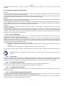
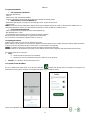
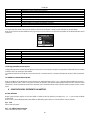
7.2 Access by name with a drop-down menu
The selection of the various menus is accessed by name. From the main menu you access menu selection
by pressing either of the ^ or ˅ keys.
Once positioned on the desired menu, it can be accessed by pressing MODE.
The available MENU items are: MAIN, USER, MONITOR and EXTENDED.
To access the Extended Menu, the access key is required, which coincides with the key combination shown
in Table 5.
The order of the menus is: User, Monitor, Setpoint, Manual, Installer, Technical Assistance.
Unlocked menus remain available for 15 minutes or until they are manually disabled through “Hide advanced menus”.
Figure 14

ENGLISH
54
Figure 15 shows an operating diagram for selecting the menus.
Figure15 Diagram of possible menu accesses
7.3 Structure of the menu pages
The following always appear on the main page
Status: operating status (e.g. standby, go, Fault, input functions)
Revs per minute: value in [rpm]
Pressure: value in [bar] or [psi] depending on the set unit of measure.
Power: value in [kW] of the power absorbed by the device.
WiFi and Bluetooth status/power through corresponding icons
Connection between telephone and available pump indicated by house symbol with drop
If the case occurs the following may appear:
Fault indications
Warning indications
Indications of the functions associated with the inputs
Specific icons
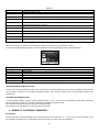
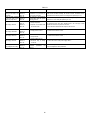
The error conditions are shown in Table 7, see chapter 10 PROTECTION SYSTEMS.
Error or status conditions shown on the main page
Identifying code
Description
GO
Motor running
SB
Motor stopped

ENGLISH
55
DIS
Motor status manually disabled
F1
Float function status / alarm
F3
System disable function status / alarm
F4
Low pressure signal function status / alarm
P1
Operating status with auxiliary setpoint 1
P2
Operating status with auxiliary setpoint 2
P3
Operating status with auxiliary setpoint 3
P4
Operating status with auxiliary setpoint 4
Com. icon with number
Operating status in multi-pump communication with the address indicated
Com. icon with E
Error status of communication in the multi-pump system
EE
Writing and reading the factory settings on EEprom
WARN. Low voltage
Warning due to lack of supply voltage
Table 7 Status and error messages on the main page
The other menu pages vary with the associated functions and are described later by type of indication or setting.
In any menu at the bottom of the page there is a status bar with the main operating parameters (status, speed and pressure).
Figure 16 Menu parameter
Indications on the status bar at the bottom of each page
Identifying code
Description
GO
Motor running
SB
Motor stopped
Disabled
Motor status manually disabled
rpm
Motor revs per minute
bar
Plant pressure
FAULT
Presence of an error preventing operation of the electropump
Table 8 Indications on the status bar
7.4 Blocking parameter setting by Password
The device has a password-enabled protection system. If a password is set, the parameters of the device will be accessible and visible but it will
not be possible to change them. The password management system is in the “technical assistance” menu and is managed by means of the
parameter PW.
7.5 Enabling and disabling the motor
In normal operating conditions, pressing and then releasing both the “^” and “˅” keys causes the blocking/release of the motor (self-holding
even after switching off). If there is a fault alarm, the operation described above resets the alarm.
When the motor is disabled this status is shown by the blinking white LED.
This command can be activated from any menu page except RF and PW.
8. MEANING OF THE INDIVIDUAL PARAMETERS
8.1 User Menu
From the main menu, pressing the MODE key (or using the selection menu and pressing ^ or ˅ ), gives access to the USER MENU. In the
menu the MODE key allows you to scroll through the various menu pages. The values shown are the following.

ENGLISH
56
8.1.1 Status
Displays the pump status.
8.1.2 RS: Rotation speed display
Motor rotation speed in rpm.
8.1.3 VP: Pressure display
Plant pressure measured in [bar] or [psi] depending on the measuring system used.
8.1.4 VF: Flow display
Displays the instantaneous flow in [litre/min] or [gal/min] depending on the set measuring system.
8.1.5 PO: Absorbed power display
Power absorbed by the electropump in [kW].
A flashing round symbol may appear under the symbol of the measured power PO. This symbol indicates the pre-alarm for exceeding the
allowed maximum power.
8.1.6 C1: Phase current display
Motor phase current in [A].
A flashing round symbol may appear under the symbol of the phase current C1. This symbol indicates the pre-alarm for exceeding the allowed
maximum current. If it flashes at regular intervals it means that the motor overload protection is about to trip and it will very probably go into
protection status.
8.1.7 TE: Heat sink temperature
Heat sink temperature display
8.1.8 Pin: Pressure at intake
Pressure at intake measured in [bar] or [psi] depending on the measuring system used.
8.1.9 Operating hours and number of starts
Indicates on three lines the hours that the device has been powered up, the pump working hours and the number of starts of the motor.
8.1.10 PI: Power histogram
A histogram of the power delivered is displayed on 5 vertical bars. The histogram indicates how long the pump has been on at a given power
level. On the horizontal axis are the bars at the various power levels; on the vertical axis, the time for which the pump has been on at the
specific power level (% of the time with respect to the total).
Figure 17 Power histogram display
8.1.11 Multi-pump system
Displays the system status when in the presence of a multi-pump installation. If communication is not present, an icon depicting communication
absent or interrupted is displayed. If there are several devices connected to one another, an icon is shown for each of them. The icon has the
symbol of a pump under which are characters indicating the pump status.
Depending on the operating status it will display as in Table 9.
System display
Status
Icon
Status information under the icon
Motor running
Symbol of pump turning
Speed in three figures
Motor stopped
Symbol of static pump
SB
Device faulty
Symbol of static pump
F
Table 9 View of the multi-pump system

ENGLISH
57
If the device is configured as reserve the icon depicting the pump is dark in colour, the display remains similar to Table 5 with the exception that,
if the motor is stopped, it shows F instead of SB.
8.1.12 NT: Display of network configurations
Information on network and serial connections for connectivity. The serial for connectivity can be displayed in full by pressing the “^” key.
8.1.13 VE: Version display
Information on the hardware version, serial number and mac address of the pump.
8.1.14 FF: Fault log display (log)
Chronological display of the faults that have occurred during system operation.
Under the symbol FF appear two numbers x/y indicating respectively the fault displayed and the total number of faults present; to the right of
these numbers is an indication of the type of fault displayed. The ^ and ˅ keys scroll through the list of faults: pressing the ˅ key goes back
through the log and stops at the oldest fault present, pressing the ^ key goes forward in the log and stops at the most recent fault.
The faults are displayed in chronological order from the one that appeared furthest back in time x=1 to the most recent one x=y. The date and
time when the fault occurred is also displayed for each one. The maximum number of faults that can be displayed is 8; when this number is
reached, the list starts to overwrite the oldest ones.
This menu item displays the list of faults, but does not allow resetting. Reset can be carried out only with the dedicated control from item RF on
the TECHNICAL ASSISTANCE MENU.
The fault log cannot be deleted with a manual reset, by switching off the appliance, or by resetting the factory values, unless the procedure
described above has been followed.
8.2 Monitor Menu
From the main menu, by holding down simultaneously for 2 sec the keys “SET” and “˅ “,or using the selection menu and pressing ^ or ˅ , you
can access the MONITOR MENU. In this menu, by pressing the MODE key, the following values are displayed in sequence.
8.2.1 BK: Display brightness
Adjusts the backlighting of the display on a scale from 0 to 100.
8.2.2 TK: Backlight switch-on time
Sets the time that the backlight is lit since the last time a key was pressed. Values allowed: ‘0’ always off; from 20 sec to 10 min or ‘always on’.
When the backlight is off, the first time any key is pressed has the sole effect of restoring the backlighting.
8.2.3 LA: Language
Display in one of the following languages:
• Italian
• English
• French
• German
• Spanish
• Dutch
• Swedish
• Turkish
• Slovak
• Romanian
• Russian
• Thai
• Portuguese
8.2.4 TE: Heat sink temperature display
8.2.5 BT: Display of the temperature of the electronic card.
8.3 Setpoint Menu
From the main menu, hold down simultaneously the “MODE” and “SET” keys until “SP” appears on the display (or use the selection menu
pressing ^ or ˅ ).
The ^ and keys allow you respectively to increase and decrease the plant boosting pressure.
Press SET to leave this menu and return to the main menu.

ENGLISH
58
8.3.1 SP: Setting the setpoint pressure
Pressure at which the system is pressurised: min 1.0 bar (14 psi) - max 12.0 bar (174 psi)
8.3.2 Setting the auxiliary pressures
The device has the possibility of varying the setpoint pressure according to the status of the inputs, up to 4 auxiliary pressures can be set for a
total of 5 different setpoints. For the electrical connections refer to the control unit manual. ; For the software settings see paragraph 9.6.15.3 -
Setting the auxiliary point input function.
If several auxiliary pressure functions associated with several inputs are active at the same time, the device will set the lowest
pressure of all the active ones.
The auxiliary setpoints can be used only through the control unit.
8.3.2.1 P1: Setting the auxiliary setpoint 1
Pressure at which the system is pressurised if the auxiliary setpoint
function is activated on input 1.
8.3.2.2 P2: Setting the auxiliary setpoint 2
Pressure at which the system is pressurised if the auxiliary setpoint
function is activated on input 2.
8.3.2.3 P3: Setting the auxiliary setpoint 3
Pressure at which the system is pressurised if the auxiliary setpoint
function is activated on input 3.
8.3.2.4 P4: Setting the auxiliary setpoint 4
Pressure at which the system is pressurised if the auxiliary setpoint
function is activated on input 4.
The pump restarting pressure is linked not only to the set pressure (SP, P1, P2, P3, P4) but also to RP. RP expresses the
decrease in pressure, with respect to “SP” (or to an auxiliary setpoint if activated), caused by the pump starting.
Example: SP = 3.0 [bar]; RP = 0.3 [bar]; no active auxiliary setpoint function: During normal operation the system is pressurised at
3.0 [bar]. The electropump restarts when the pressure falls below 2.7 [bar].
Setting a pressure (SP, P1, P2, P3, P4) that is too high for the pump performance may cause false water lack errors BL; in these
cases lower the set pressure.
8.4 Manual Menu
From the main menu, hold down simultaneously the “SET” and “^” and “˅“keys until the manual menu page appears (or use the selection menu
pressing ^ or ˅).
The menu allows you to view and modify various configuration parameters: the MODE key allows you to scroll through the menu pages, the ^
and ˅ keys allow you respectively to increase and decrease the value of the parameter concerned. Press SET to leave this menu and return to
the main menu. Entering the manual menu by pressing the SET ^ ˅ keys puts the machine into forced STOP condition. This function can be
used to force the machine to stop. In manual mode, irrespective of the parameter displayed, it is always possible to perform the following
controls:
Temporary starting of the electropump
Pressing the MODE and ^ keys at the same time causes the pump to start at speed RI and this running status remains as long as the two keys
are held down.
When the pump ON of pump OFF command is given, a communication appears on the display.
Starting the pump
Holding down the MODE ˅ ^ keys simultaneously for 2 sec. causes the pump to start at speed RI. The running status remains until the SET key
is pressed. The next time the SET key is pressed the pump leaves the manual menu. When the pump ON of pump OFF command is given, a
communication appears on the display. In case of operation in this mode for more than 5’ with no flow of liquid, an alarm overheating alarm will
be triggered, with the error PH shown on the display. Once the PH error condition is no longer present, the alarm will be reset automatically
only. The reset time is 15’; if the PH error occurs more than 6 times consecutively, the reset time increases to 1h.
Once it has reset further to this error, the pump will remain in stop status until the user restarts it using the “MODE” “˅” “^”keys.

ENGLISH
59
8.4.1 Status
Displays the pump status.
8.4.2 RI: Speed setting
Sets the motor speed in rpm. Allows you to force the number of revolutions at a predetermined value.
8.4.3 VP: Pressure display
Plant pressure measured in [bar] or [psi] depending on the measuring system used.
8.4.4 VF: Flow display
Displays the flow in the chosen unit of measure. The measuring unit may be [l/min] o [gal/min] see par. 8.5.4 - MS: Measuring system.
8.4.5 PO: Absorbed power display
Power absorbed by the electropump in [kW]. A flashing round symbol may appear under the symbol of the measured power PO. This symbol
indicates the pre-alarm for exceeding the allowed maximum power.
8.4.6 C1: Phase current display
Motor phase current in [A]. A flashing round symbol may appear under the symbol of the phase current C1. This symbol indicates the pre-alarm
for exceeding the allowed maximum current. If it flashes at regular intervals it means that the motor overload protection is about to trip and it will
very probably go into protection status.
8.4.7 RS: Rotation speed display
Motor rotation speed in rpm.
8.4.8 TE: Heat sink temperature display
8.5 Installer Menu
From the main menu, hold down simultaneously the “MODE” and “SET” and “˅” keys until the first parameter of the installer menu appears on
the display (or use the selection menu pressing ^ or ˅ ).
The menu allows you to view and modify various configuration parameters: the MODE key allows you to scroll through the menu pages, the ^
and ˅ keys allow you respectively to increase and decrease the value of the parameter concerned. Press SET to leave this menu and return to
the main menu.
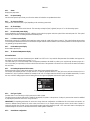
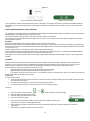
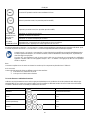
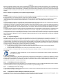
8.5.1 RP: Setting the pressure fall to restart
Expresses the fall in pressure with respect to the SP value which causes restarting of the pump.
For example if the setpoint pressure is 3.0 [bar] and RP is 0.3 [bar] the pump will restart at 2.7 [bar]. RP can be set from a minimum of 0.1 to a
maximum of 1 [bar]. In particular conditions (for example in the case of a setpoint lower than the RP) it may be limited automatically. To assist
the user, on the RP setting page the actual restarting pressure also appears highlighted under the RP symbol, see Figure 18.
Figure 18 Setting the restart pressure
8.5.2 OD: Type of plant
Possible values 1 and 2 referring to a rigid system and an elastic system.
The device leaves the factory with mode 1 suitable for the majority of systems. In the presence of swings in pressure that cannot be stabilised
by adjusting the parameters GI and GP, change to mode 2.
IMPORTANT: The regulating parameters GP and GI also change in the two configurations. In addition the GP and GI values set in mode 1 are
stored in a different memory from the GP and GI values set in mode 2. So, for example, when passing to mode 2, the GB value of mode 1 is
replaced by the GB value of mode 2 but it is kept and will reappear again when returning to mode 1. The same value shown on the display has
a different weight in one mode or in the other because the control algorithm is different.
8.5.3 AD: Address configuration
La page est en cours de chargement...
La page est en cours de chargement...
La page est en cours de chargement...
La page est en cours de chargement...
La page est en cours de chargement...
La page est en cours de chargement...
La page est en cours de chargement...
La page est en cours de chargement...
La page est en cours de chargement...
La page est en cours de chargement...
La page est en cours de chargement...
La page est en cours de chargement...
La page est en cours de chargement...
La page est en cours de chargement...
La page est en cours de chargement...
La page est en cours de chargement...
La page est en cours de chargement...
La page est en cours de chargement...
La page est en cours de chargement...
La page est en cours de chargement...
La page est en cours de chargement...
La page est en cours de chargement...
La page est en cours de chargement...
La page est en cours de chargement...
La page est en cours de chargement...
La page est en cours de chargement...
La page est en cours de chargement...
La page est en cours de chargement...
La page est en cours de chargement...
La page est en cours de chargement...
La page est en cours de chargement...
La page est en cours de chargement...
La page est en cours de chargement...
La page est en cours de chargement...
La page est en cours de chargement...
La page est en cours de chargement...
La page est en cours de chargement...
La page est en cours de chargement...
La page est en cours de chargement...
La page est en cours de chargement...
La page est en cours de chargement...
La page est en cours de chargement...
La page est en cours de chargement...
La page est en cours de chargement...
La page est en cours de chargement...
La page est en cours de chargement...
La page est en cours de chargement...
La page est en cours de chargement...
La page est en cours de chargement...
La page est en cours de chargement...
La page est en cours de chargement...
La page est en cours de chargement...
La page est en cours de chargement...
La page est en cours de chargement...
La page est en cours de chargement...
La page est en cours de chargement...
La page est en cours de chargement...
La page est en cours de chargement...
La page est en cours de chargement...
La page est en cours de chargement...
La page est en cours de chargement...
La page est en cours de chargement...
La page est en cours de chargement...
La page est en cours de chargement...
-
 1
1
-
 2
2
-
 3
3
-
 4
4
-
 5
5
-
 6
6
-
 7
7
-
 8
8
-
 9
9
-
 10
10
-
 11
11
-
 12
12
-
 13
13
-
 14
14
-
 15
15
-
 16
16
-
 17
17
-
 18
18
-
 19
19
-
 20
20
-
 21
21
-
 22
22
-
 23
23
-
 24
24
-
 25
25
-
 26
26
-
 27
27
-
 28
28
-
 29
29
-
 30
30
-
 31
31
-
 32
32
-
 33
33
-
 34
34
-
 35
35
-
 36
36
-
 37
37
-
 38
38
-
 39
39
-
 40
40
-
 41
41
-
 42
42
-
 43
43
-
 44
44
-
 45
45
-
 46
46
-
 47
47
-
 48
48
-
 49
49
-
 50
50
-
 51
51
-
 52
52
-
 53
53
-
 54
54
-
 55
55
-
 56
56
-
 57
57
-
 58
58
-
 59
59
-
 60
60
-
 61
61
-
 62
62
-
 63
63
-
 64
64
-
 65
65
-
 66
66
-
 67
67
-
 68
68
-
 69
69
-
 70
70
-
 71
71
-
 72
72
-
 73
73
-
 74
74
-
 75
75
-
 76
76
-
 77
77
-
 78
78
-
 79
79
-
 80
80
-
 81
81
-
 82
82
-
 83
83
-
 84
84


dans d''autres langues
- English: DAB Esybox Max User manual
Documents connexes
-
DAB E.SYBOX Mode d'emploi
-
-
-
DAB E.SYBOX MINI 3 Manuel utilisateur
-
-
DAB ESYBOX Mode d'emploi
-
-
-
DAB ESYBOX DIVER 55/120 Manuel utilisateur