DAB DAB E.SYBOX Instruction For Installation And Maintenance
- Taper
- Instruction For Installation And Maintenance

ISTRUZIONI PER L’INSTALLAZIONE E LA MANUTENZIONE
INSTRUCTIONS FOR INSTALLATION AND MAINTENANCE
INSTRUCTIONS POUR L’INSTALLATION ET L’ENTRETIEN
BEDIENUNGS- UND WARTUNGSANWEISUNGEN
GEBRUIKS- EN ONDERHOUDSAANWIJZINGEN
GE
BR
UI
KS
-
EN
O
ND
ER
HO
UD
SA
AN
WI
JZ
IN
GE


4
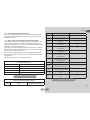
(IT) DICHIARAZIONE DI CONFORMITÀ CE
Noi, DAB Pumps S.p.A. - Via M.Polo, 14 - Mestrino (PD) - Italy, dichiariamo sotto
la nostra esclusiva responsabilità che il prodotto al quale questa dichiarazione si
riferisce è conforme alle seguenti direttive
2006/95/CE
2004/108/CE
2009/125/EC ErP
2011/65/EU
ed alle seguenti norme:
EN 60335-2-41
EN 60335-1
EN 55014-1
EN 55014-2
(FR) DÉCLARATION DE CONFORMITÉ CE
Nous, DAB Pumps S.p.A. - Via M.Polo, 14 - Mestrino (PD) - Italie, déclarons sous
notre responsabilité exclusive que le produit auquel la présente déclaration fait
référence est conforme aux directives
2006/95/CE
2004/108/CE
2009/125/EC ErP
2011/65/EU
ainsi qu’aux normes suivantes:
EN 60335-2-41
EN 60335-1
EN 55014-1
EN 55014-2
(GB) DECLARATION OF CONFORMITY CE
We, DAB Pumps S.p.A. - Via M.Polo, 14 - Mestrino (PD) - Italy, declare under our
responsibility that the product to which this declaration refers is in conformity with
the following directives:
2006/95/CE
2004/108/CE
2009/125/EC ErP
2011/65/EU
and with the following standards:
EN 60335-2-41
EN 60335-1
EN 55014-1
EN 55014-2
(DE) EG-KONFORMITÄTSERKLÄRUNG
Wir, DAB Pumps S.p.A. - Via M.Polo, 14 – Mestrino (PD) – Italy, erklären unter
unserer ausschließlichen Verantwortlichkeit, dass die Produkte auf die sich diese
Erklärung bezieht, den folgenden Richtlinien:
2006/95/CE
2004/108/CE
2009/125/EC ErP
2011/65/EU
sowie den folgenden Normen entsprechen:
EN 60335-2-41
EN 60335-1
EN 55014-1
EN 55014-2
DECLARATION OF CONFORMITY

5
(NL) EG-VERKLARING VAN OVEREENSTEMMING
Wij, DAB Pumps S.p.A. - Via M.Polo, 14 – Mestrino (PD) – Italy, verklaren uitslu-
itend voor eigen verantwoordelijkheid dat de producten waarop deze verklaring
betrekking heeft, conform de volgende richtlijnen zijn:
2006/95/CE
2004/108/CE
2009/125/EC ErP
2011/65/EU
en conform de volgende normen:
EN 60335-2-41
EN 60335-1
EN 55014-1
EN 55014-2
DECLARATION OF CONFORMITY
Mestrino (PD) 01/01/2013
Francesco Sinico
Technical Director

ENGLISH
GB
60
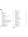
INDEX
Key 63
Warnings 63
Responsibility 64
1. General 64
1.1 Description of the Integrated Inverter 65
1.2 Integrated expansion vessel 65
1.3 Integrated electropump 66
1.4 Technical characteristics 67
2. Installation 68
2.1 9HUWLFDO&RQ¿JXUDWLRQ 68
2.1.1 Hydraulic connections 69
2.1.2 Loading operation – Installation above head and below head 70
2.2 +RUL]RQWDOFRQ¿JXUDWLRQ 70
2.2.1 Hydraulic connections 70
2.2.2 Orientation of the interface panel 71
2.2.3 Loading operation – Installation above head and below head 72
3. Commissioning 72
3.1 Electrical connections 72
3.2 &RQ¿JXUDWLRQRIWKHLQWHJUDWHGLQYHUWHU 72
3.3 Priming 72
4. Protection systems 74
4.1 Description of blockages 74
4.1.1 “BL” AAnti Dry-Run (Protection against dry running) 74
4.1.2 Anti-Cycling (Protection against continuous cycles without utility request) 74
4.1.3 Anti-Freeze (Protection against freezing of water in the system) 74
4.1.4 “BP1” Blockage due to fault of the internal pressure sensor 75
4.1.5 “BP2” Blockage due to reading error on the remote pressure sensor 75
4.1.63%´%ORFNDJHGXHWROLQHYROWDJHRXWVLGHVSHFL¿FDWLRQV
4.1.7 “SC” Blockage due to short circuit between the motor phases 75
4.2 Manual reset of error conditions 76
4.3 Self-reset of error conditions 76
5. Inverter electronic control and user interface 76
5.1 Electrical connections of utility inputs and outputs 76
6. The keypad and the display 79
6.1 Direct access with a combination of keys 80
6.2 Access by name with a drop-down menu 84
6.3 Structure of the menu pages 85
6.4 Blocking parameter setting by Password 86
6.5 Enabling and disabling the motor 86
7. Meaning of the individual parameters 86
7.1 User Menu 86
7.1.1 Status 87
7.1.2 RS: Rotation speed display 87
7.1.3 VP: Pressure display 87
7.1.4 VF: Flow display 87
7.1.5 PO: Absorbed power display 87
7.1.6 C1: Phase current display 87
7.1.7 Operating hours and number of starts 87
7.1.8 Multi-pump system 87
7.1.9 VE: Version display 87
7.1.10 PI: Power histogram 88
7.1.11 FF: Fault log display 88
7.2 Monitor Menu 88
7.2.1 CT: Display contrast 88
7.2.2 BK: Display brightness 88
7.2.3 TK: Backlight switch-on time 88
7.2.4 LA: Language 88
7.2.5 TE: Dissipator temperature display 88
7.3 Setpoint Menu 88
7.3.1 SP: Setting the setpoint pressure 89
7.3.2 Setting the auxiliary pressures 89
7.3.2.1 P1: Setting the auxiliary setpoint 1 89
7.3.2.2 P2: Setting the auxiliary setpoint 2 89
7.3.2.3 P3: Setting the auxiliary setpoint 3 89
7.3.2.4 P4: Setting the auxiliary setpoint 4 89
7.4 Manual Menu 89
7.4.1 Status 90
7.4.2 RI: Speed setting 90
7.4.3 VP: Pressure display 90
7.4.4 VF: Flow display 90
7.4.5 PO: Absorbed power display 90
7.4.6 C1: Phase current display 90
7.4.7 RS: Rotation speed display 90
7.4.8 TE: Dissipator temperature display 90
7.5 Installer Menu 90
7.5.1 RP: Setting the pressure fall to restart 90
7.5.2 OD: Type of plant 90
$'$GGUHVVFRQ¿JXUDWLRQ 91
7.5.4 MS: Measuring system 91
7.5.5 AS: Association of devices 91
7.5.6 PR: Remote pressure sensor 92
7.6 Technical Assistance Menu 92
7.6.1 TB: Water lack blockage time 92

ENGLISH
GB
6161
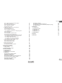
7.6.2 T1: Switch-off time after low pressure signal 92
7.6.3 T2: Delay in switching off 92
*33URSRUWLRQDOJDLQFRHI¿FLHQW 93
*,,QWHJUDOJDLQFRHI¿FLHQW 93
7.6.6 RM: Maximum speed 93
7.7 Setting the number of devices and of reserves 93
7.7.1 NA: Active devices 93
7.7.2 NC: Simultaneous devices 93
,&&RQ¿JXUDWLRQRIWKHUHVHUYH 93
([DPSOHVRIFRQ¿JXUDWLRQIRUPXOWLSXPSV\VWHPV 94
7.7.4 ET: Exchange time 94
7.7.5 AY: Anti Cycling 95
7.7.6 AE: Enabling the anti-block function 95
7.7.7 AF: Enabling the anti-freeze function 95
7.7.8 Setup of the auxiliary digitali inputs IN1, IN2, IN3, IN4 95
7.7.8.1 Disabling the functions associated with the input 96
6HWWLQJH[WHUQDOÀRDWIXQFWLRQ 96
7.7.8.3 Setting auxiliary setpoint input function 96
7.7.8.4 Setting system enabling and fault reset 97
7.7.8.5 Setting low pressure detection (KIWA) 98
7.8 Setup of the outputs OUT1, OUT2 98
7.8.1 O1: Setting output 1 function 99
7.8.2 O2: Setting output 2 function 99
7.9 RF: Fault and warning reset 99
7.10 PW: Change password 99
7.10.1 Password for multipump systems 100
8. Reset and factory settings 100
8.1 Reset generale del sistema
100
8.2 Factory settings 100
8.3 Restoring the factory settings 100
9. Particular installations 101
9.1 Inhibiting self-priming 101
9.2 Wall installation 102
9.3 Installation with Quick Connection 103
9.4 Multiple Sets 103
9.4.1 Introduction to multipump systems 103
9.4.2 Making a multipump system 103
9.4.3 Wireless communication 104
9.4.4 Connection and setting of the photocoupled inputs 104
9.4.5 Parameters linked to multipump operation 104
9.4.6 First start of the multipump system 105
9.4.7 Multipump adjustment 105
9.4.8 Assigning the starting order 106
9.4.9 Maximum work time 106
9.4.10 Reaching the maximum inactivity time 106
9.4.11 Reserves and number of devices that participate in pumping 106
9.4.12 Wireless Control 107
10. Maintenance 107
10.1 Accessory tool 107
10.2 Emptying the system 109
10.3 Non-return valve 109
10.4 Motor shaft 110
10.5 Expansion Vessel 110
11. Troubleshooting 111
12. Disposal 112
13. Guarantee 112


The appliance is not intended to be used by persons (including
children) with reduced physical, sensory or mental capacities,
or who lack experience or knowledge, unless, through the
mediation of a person responsible for their safety, they have
KDGWKHEHQH¿WRIVXSHUYLVLRQRURILQVWUXFWLRQVRQWKHXVHRI
the appliance. Children must be supervised to ensure that they
do not play with the appliance. (EN 60335-1: 02).
Safety
Use is allowed only if the electric system is in possession of
safety precautions in accordance with the regulations in force in
the country where the product is installed (for Italy CEI 64/2).
Pumped liquids
The machine has been designed and made for pumping water,
IUHHIURPH[SORVLYHVXEVWDQFHVDQGVROLGSDUWLFOHVRU¿EUHV
with a density of 1000 Kg/m³, a kinematic viscosity of 1mm²/s
and non chemically aggressive liquids.
The power supply cable must never be used to carry or shift the
pump.
Never pull on the cable to detach the plug from the socket.
If the power cable is damaged, it must be replaced by the
manufacturer or by their authorised technical assistance
service, so as to avoid any risk.
Failure to observe the warnings may create situations of risk for persons
or property and will void the product guarantee.
KEY
The following symbols have been used in the discussion:
Situation of general danger. Failure to respect the instruc-
tions that follow may cause harm to persons and property.
Situation of electric shock hazard. Failure to respect the
instructions that follow may cause a situation of grave risk for
personal safety.
Notes
WARNINGS
Read this documentation carefully before installation.
Installation and operation must comply with the local safety reg-
ulations in force in the country in which the product is installed.
Everything must be done in a workmanlike manner.
Failure to respect the safety regulations not only causes risk to
personal safety and damage to the equipment, but invalidates
every right to assistance under guarantee.
Skilled personnel
It is advisable that installation be carried out by competent,
VNLOOHGSHUVRQQHOLQSRVVHVVLRQRIWKHWHFKQLFDOTXDOL¿FDWLRQV
UHTXLUHGE\WKHVSHFL¿FOHJLVODWLRQLQIRUFH
The term skilled personnel means persons whose training,
experience and instruction, as well as their knowledge of the
respective standards and requirements for accident prevention
and working conditions, have been approved by the person in
charge of plant safety, authorizing them to perform all the nec-
essary activities, during which they are able to recognize and
DYRLGDOOGDQJHUV'H¿QLWLRQIRUWHFKQLFDOSHUVRQQHO,(&
ENGLISH
GB
63

ENGLISH
GB
64
RESPONSIBILITY
The Manufacturer does not vouch for correct operation of
the electropumps or answer for any damage that they may
FDXVHLIWKH\KDYHEHHQWDPSHUHGZLWKPRGL¿HGDQGRUUXQ
outside the recommended work range or in contrast with
other indications given in this manual.
The Manufacturer declines all responsibility for possible
errors in this instructions manual, if due to misprints or
errors in copying. The Manufacturer reserves the right to
PDNHDQ\PRGL¿FDWLRQVWRSURGXFWVWKDWLWPD\FRQVLGHU
necessary or useful, without affecting their essential char-
acteristics.
1- GENERAL
The product is an integrated system composed mainly of a self-priming
multi-stage centrifugal electropump, an electronic control unit that
controls it and an expansion vessel.
Applications
Water systems supply and pressure boosting domestic use or industrial
use.
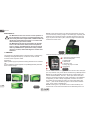
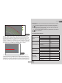
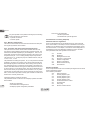
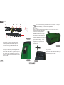
On the outside the product appears as a parallelepiped that presents 6
faces as shown in Fig.1.
A B C D
E
F
Figure 1
A
B
E
F
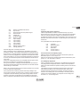
Face A: a door allows access to the Technical Compartment. The door
FDQEHUHPRYHGE\LQVHUWLQJ¿QJHUVLQWKHUXEEHUJULSVVTXHH]LQJDQG
rotating the door around the hinges on the side opposite the grips (see
Fig.2). To put the door back in place, insert the hinges in their slots and
close the door until it clicks.
Inside the technical compartment you can access (see Fig.3):
1. Valve of the expansion vessel;
2. Technical data plate;
3. Rapid Guide;
4. Motor shaft;
5. Accessory tool;
6. Filling cap (only for vertical
FRQ¿JXUDWLRQ
Face B: a removable screw cap gives access to the non return valve (see
par. 10.3). Remove it only in the case of maintenance by skilled personnel.
Face C: the 4 brass threads form the seat for the 4 support feet in the
case of vertical installation. The two 1” screw caps can be removed to
make the connections towards the system, depending on the installation
FRQ¿JXUDWLRQ\RXZDQWWRDGRSW,IDSSOLFDEOHFRQQHFWWRWKHFRQQHF-
tion marked “IN” the system from which you want to draw water (well,
cistern,…) and connect the delivery system to the connection marked
“OUT”. There is also a ventilation grid.
Face D: removing the 1” cap allows access to a second delivery con-
nection which can be used at the same time or alternatively to the one
Figure 2
Figure 3

ENGLISH
GB
65
marked ”OUT” of face C. The power supply cable is for connection to the
power mains.
Face E: the 4 brass threads form the seat for the 4 support feet in the
case of horizontal installation. The 1” cap has the main function of empty-
ing the system. There are also 2 ventilation grids.
Face F: as indicated by the label to be removed, the 1” cap has a dual
function: in the case of horizontal installation, the outlet that is closed by
the cap acts as the system’s loading door (see below “loading opera-
tions”, par. 2.2.3); in the case of vertical installation, the same outlet can
act as the input hydraulic connection (exactly like the one marked “IN” on
face C and as an alternative to it). The user interface panel is composed
of a display and a keyboard and its function is to set the system, query its
status and communicate any alarms.
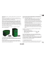
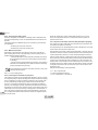
7KHV\VWHPFDQEHLQVWDOOHGLQGLIIHUHQWFRQ¿JXUDWLRQVKRUL]RQWDO
(Fig.4) or vertical (Fig.5).
1.1 Description of the Integrated Inverter
The electronic control integrated in the system is of the type with inverter
DQGLWPDNHVXVHRIÀRZSUHVVXUHDQGWHPSHUDWXUHVHQVRUVDOVRLQWH-
grated in the system.
By means of these sensors the system switches on and off automati-
cally according to the utility’s needs and it is able to detect conditions of
malfunction, to prevent and indicate them.
Figure 4
Figure
Figure 5
The Inverter control ensures different functions, the most important of
which, for pumping systems, are the maintaining of a constant pressure
value in delivery and energy saving.
7KHLQYHUWHULVDEOHWRNHHSWKHSUHVVXUHRIDK\GUDXOLFFLUFXLW
constant by varying the rotation speed of the electropump.
In operation without an inverter the electropump is unable to
PRGXODWHDQGZKHQWKHUHLVDQLQFUHDVHRIWKHUHTXHVWIRUÀRZ
the pressure necessarily decreases, or vice versa; this means the
SUHVVXUHVDUHWRRKLJKDWORZÀRZUDWHVRUWRRORZZKHQWKHUHLV
DQLQFUHDVHGUHTXHVWIRUÀRZ
%\YDU\LQJWKHURWDWLRQVSHHGDFFRUGLQJWRWKHLQVWDQWDQHRXV
request of the utility, the inverter limits the power supplied to the
electropump to the minimum necessary to ensure that the re-
TXHVWLVVDWLV¿HG,QVWHDGRSHUDWLRQZLWKRXWDQLQYHUWHUFRQWHP-
plates operation of the electropump always and only at maximum
power.
7KHV\VWHPLVFRQ¿JXUHGE\WKHPDQXIDFWXUHUWRVDWLVI\WKHPDMRULW\RI
installation cases, that is:
Operation at constant pressure;
Set-Point (desired value of constant pressure:SP = 3.0 bar
Reduction of pressure to restart: RP = 0.3 bar
Anti-cycling function: Disabled
However, these parameters and others can be set according to the
system. All the settable values are illustrated in the par. 5-6-7: pressure,
intervention of protections, rotation speed, etc.
There are many other operating modes and accessory functions. Thanks
WRWKHGLIIHUHQWSRVVLEOHVHWWLQJVDQGWKHDYDLODELOLW\RIFRQ¿JXUDEOHLQSXW
and output channels, it is possible to adapt the inverter operation to the
requirements of various systems. See 5-6-7.
1.2 Integrated Expansion Vessel
The system is complete with an integrated expansion vessel with a total
capacity of 2 litres. The main functions of the expansion vessel are:

ENGLISH
GB
66
WRPDNHWKHV\VWHPHODVWLFVRDVWRSURWHFWLWDJDLQVWZDWHU
hammer;
WRHQVXUHDZDWHUUHVHUYHZKLFKLQWKHFDVHRIVPDOOOHDNV
maintains the pressure in the system for a longer time and
spreads out needless restarts of the system which otherwise
would be continuous;
ZKHQWKHXWLOLW\LVWXUQHGRQHQVXUHWKHZDWHUSUHVVXUHIRUWKH
seconds that the system takes to switch on and reach the correct
rotation speed.
It is not a function of the integrated expansion vessel to ensure a water
reserve such as to reduce interventions of the system (requests from the
utility, not from a leak in the system). It is possible to add an expansion
vessel with the capacity you prefer to the system, connecting it to a point
on the delivery system (not a suction point!). In the case of horizontal
installation it is possible to connect to the unused delivery outlet. When
choosing the tank, consider that the quantity of water released will also
depend on the parameters SP and RP that can be set on the system
(par.6-7).
The expansion vessel is preloaded with pressurised air through the valve
accessible from the technical compartment (Fig.3, point 1). The preload
value with which the expansion vessel is supplied by the manufacturer is
in agreement with the parameters SP and RP set as default, and anyway
LWVDWLV¿HVWKHIROORZLQJHTXDWLRQ
Pair = SP – RP – 0.7bar Where:
- Pair = air pressure value in bar
- SP = Set Point (par.7.3) in bar
- RP = Reduction of pressure to restart
(par. 7.5.1) in bar
So, by the manufacturer: Pair = 3.0 – 0.3 – 0.7 = 2.0 bar
If different values are set for the parameters SP and/or RP, regulate the
valve of the expansion vessel releasing or letting in air until the above
HTXDWLRQLVVDWLV¿HGDJDLQHJ63 EDU53 EDUUHOHDVHDLUIURP
the expansion vessel until a pressure of 1.5bar is reached on the valve).
Failure to respect the above equation may lead to malfunctions
of the system or to premature breakage of the diaphragm inside
the expansion vessel.
Considering the expansion vessel capacity of only 2 litres, any
operation to check the air pressure must be performed by con-
necting the pressure gauge very rapidly: on small volumes the
loss of even a limited quantity of air can cause an appreciable
drop in pressure. The quality of the expansion vessel ensures
the maintenance of the set air pressure value, proceed to check
it only at calibration or if you are sure of a malfunction.
Any operation to check and/or reset the air pressure must
be performed with the delivery system not under pressure:
disconnect the pump from the power supply and open the utility
nearest to the pump, keeping it open until it no longer gives any
water.
The special structure of the expansion vessel ensures its quan-
tity and duration over time, especially of the diaphragm which
is typically the component subject to wear for items of this type.
However, in the case of breakage, the entire expansion vessel
must be replaced and exclusively by authorised personnel.
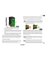
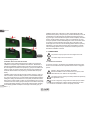
1.3 Integrated electropump
7KHV\VWHPKDVDEXLOWLQPXOWLLPSHOOHUFHQWULIXJDOHOHFWURSXPS6SHFL¿-
cally, the electropump comprises a hydraulic assembly of 5 impellers
driven by a water-cooled three-phase electric motor. Cooling of the motor
with water rather than air ensures less noise in the system and the pos-
sibility of locating it even in recesses without ventilation.
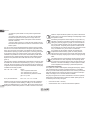
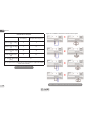
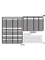
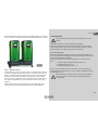
The graph in Fig.6 shows in red the characteristic curve of the hydraulic
performance of the electropump at maximum rotation speed (pump not
controlled by the inverter). This gives:
PD[LPXPÀRZUDWH OPLQ
maximum head = 65 m => about 6.5 bar maximum pressure.

ENGLISH
GB
67
Failure to respect the above equation may lead to malfunctions
of the system or to premature breakage of the diaphragm inside
the maintenance of the set air pressure value, proceed to check
disconnect the pump from the power supply and open the utility
nearest to the pump, keeping it open until it no longer gives any
is typically the component subject to wear for items of this type.
7KHV\VWHPKDVDEXLOWLQPXOWLLPSHOOHUFHQWULIXJDOHOHFWURSXPS6SHFL¿
driven by a water-cooled three-phase electric motor. Cooling of the motor
PD[LPXPÀRZUDWH OPLQ
(set up)
(set up)
(set up)
(set up)
(set up)
(set up)
0
5
10
15
20
25
30
35
40
45
50
55
60
65
0 10 20 30 40 50 60 70 80 9 0 100 110 120 130
H (m)
Q (lt/1')
3000 rpm (impostati)
2700 rpm (impostati)
2400 rpm (impostati)
2100 rpm (impostati)
1800 rpm (impostati)
1500 rpm (impostati)
Figure 6
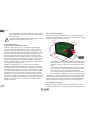
The same graph in Fig.6 shows in green other characteristic curves
corresponding to reduced rotation speeds of the same electropump.
By
automatically modulating the rotation speed of the electropump, the in-
verter allows it to move its operation from one of the characteristic curves
to another, maintaining the constant set pressure value (SP). Practically,
the resulting curve of the system controlled by the inverter becomes the
one shown in Fig.7 (considering a default SP value = 3.0 bar).
This means that, with SP = 3.0 bar, the system is able to ensure the
FRQVWDQWVHWSUHVVXUHWRXWLOLWLHVWKDWUHTXLUHÀRZUDWHVEHWZHHQDQG
OLWUHVPLQXWH)RUKLJKHUÀRZUDWHVWKHV\VWHPZRUNVDFFRUGLQJWRWKH
characteristic curve of the electropump at maximum rotation speed. For
ÀRZUDWHVORZHUWKDQOLWUHVPLQXWHDVZHOODVHQVXULQJFRQVWDQWSUHV-
Figure 7
0
5
10
15
20
25
30
35
40
45
50
55
60
65
0 10 20 30 4 0 50 60 70 80 90 100 110 120 1 30
H (m)
Q (lt/1')
sure, the system reduces the absorbed power and therefore the energy
consumption.
The above performances are to be considered measured at
DPELHQWWHPSHUDWXUHDQGZDWHUDWDERXW&GXULQJWKH¿UVW
10 minutes of motor operation, with water level at suction at a
depth of no more than 1 metre
As the suction depth increases, the performance of the electro-
pump decreases.
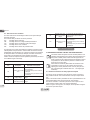
1.4 Technical characteristics
ELECTRIC POWER
SUPPLY
Voltage 1 x 220/240 ~ VAC
Frequency 50/60 Hz
Maximum current 11 A
Maximum power 1550 W
CONSTRUCTION
CHARACTERISTICS
Overall dimensions 565x265x352 mm without
feet
Empty weight (excluding
packaging)
24,8 kg
Protection class IP x4
Motor insulation class F
HYDRAULIC
PERFORMANCE
Maximum head 65 m
0D[LPXPÀRZUDWH 120 l/min
Priming <5min at 8m
WORKING
CONDITIONS
Maximum working pressure 8 bar
Liquid temperature max 40 °C
Environment temperature
max
50 °C
Storage environment
temperature
-10÷60 °C

ENGLISH
GB
68
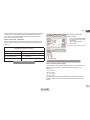
FUNCTIONALITY
AND
PROTECTIONS
Constant pressure
Wireless communication
Protection against dry running
Antifreeze protection
Anticycling protection
Motor overload protection
Protection against abnormal supply voltages
Protection against excess temperature
2- INSTALLATION
The system is designed for indoor use: do not install the system
outdoors and/or directly exposed to atmospheric agents.
The system is designed to be able to work in environments
where the temperature remains between 0°C and 50°C (on
condition that the electric power supply is ensured: see par.
7.7.7 “anti-freeze function”).
The system is suitable for treating drinking water.
The system cannot be used to pump salt water, sewage,
LQÀDPPDEOHFRUURVLYHRUH[SORVLYHOLTXLGVHJSHWUROHXP
petrol, thinners), greases, oils or food products.
The system can take in water the level of which must not be at
a depth greater than 8m (the height between the water level
and the pump suction mouth).
If the system is used for the domestic water supply, respect the
local regulations of the authorities responsible for the manage-
ment of water resources.
When choosing the installation site, check that:
7KHYROWDJHDQGIUHTXHQF\RQWKHSXPS¶VWHFKQLFDOGDWD
plate correspond to the values of the power supply system.
7KHHOHFWULFDOFRQQHFWLRQLVPDGHLQDGU\SODFHIDUIURP
DQ\SRVVLEOHÀRRGLQJ
The electrical system is provvided with a differential switch
ZLWK,ǻQP$DQGWKDWWKHHDUWKV\VWHPLVHI¿FLHQW
If you are not sure of the absence of foreign bodies in the water to be
SXPSHGLQVWDOOD¿OWHURQWKHV\VWHPLQWDNHWKDWLVVXLWDEOHIRUFDWFKLQJ
impurities.
7KHLQVWDOODWLRQRID¿OWHURQLQWDNHFDXVHVDGHFUHDVHRIWKH
system’s hydraulic performance proportional to the loss of load
FDXVHGE\WKH¿OWHULWVHOIJHQHUDOO\WKHJUHDWHUWKH¿OWHULQJ
power, the greater the fall in performance).
&KRRVHWKHW\SHRIFRQ¿JXUDWLRQ\RXLQWHQGWRXVHYHUWLFDORUKRUL]RQWDO
considering the connections to the system, the position of the user inter-
face panel, and the spaces available according to the indications below.
2WKHUW\SHVRILQVWDOODWLRQFRQ¿JXUDWLRQDUHSRVVLEOHXVLQJ'$%DFFHV-
sory interfaces: see dedicated paragraph (par.9.2, 9.3).
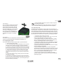
9HUWLFDO&RQ¿JXUDWLRQ
Remove the 4 support feet from the bottom tray of the packaging and
screw them fully into their brass seats on face C. Put the system in place,
taking into account the dimensions in Fig.8.

ENGLISH
GB
69
7KHGLVWDQFHRIDWOHDVWPPEHWZHHQ)DFH(RIWKH
system and any wall is obligatory to ensure ventilation
through the grids provided.
7KHGLVWDQFHRIDWOHDVWPPEHWZHHQ)DFH%RIWKHV\VWHP
and an obstruction is recommended so as to be able to carry out
maintenance on the non-return valve without disconnecting the
system.
7KHGLVWDQFHRIDWOHDVWPPEHWZHHQ)DFH$RIWKHV\VWHP
and an obstruction is recommended so as to be able to remove
the door and gain access to the technical compartment.
,IWKHVXUIDFHLVQRWÀDWXQVFUHZWKHIRRWWKDWLVQRWWRXFKLQJDQGDGMXVW
its height until it contacts the surface so as to ensure the stability of the
system. The system must in fact be placed in a safe and stable position,
ensuring that its axis is vertical: it must not be in an inclined position.
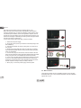
2.1.1 Hydraulic connections
Make the connection at input to the system through the mouth on Face
F marked “IN” in Fig.8 (suction connection). Then remove the respective
cap with the aid of the accessory tool or with a screwdriver.
Make the connection at output from the system through the mouth on
7KHYROWDJHDQGIUHTXHQF\RQWKHSXPS¶VWHFKQLFDOGDWD
7KHHOHFWULFDOFRQQHFWLRQLVPDGHLQDGU\SODFHIDUIURP
DQ\SRVVLEOHÀRRGLQJ
The electrical system is provvided with a differential switch
ZLWK,ǻQP$DQGWKDWWKHHDUWKV\VWHPLVHI¿FLHQW
SXPSHGLQVWDOOD¿OWHURQWKHV\VWHPLQWDNHWKDWLVVXLWDEOHIRUFDWFKLQJ
7KHLQVWDOODWLRQRID¿OWHURQLQWDNHFDXVHVDGHFUHDVHRIWKH
FDXVHGE\WKH¿OWHULWVHOIJHQHUDOO\WKHJUHDWHUWKH¿OWHULQJ
&KRRVHWKHW\SHRIFRQ¿JXUDWLRQ\RXLQWHQGWRXVHYHUWLFDORUKRUL]RQWDO
2WKHUW\SHVRILQVWDOODWLRQFRQ¿JXUDWLRQDUHSRVVLEOHXVLQJ'$%DFFHV
9HUWLFDO&RQ¿JXUDWLRQ
w them fully into their brass seats on face C. Put the system in place,
10 mm
200 mm
270 mm
IN
OUT
580 mm
355 mm
265 mm
Figure 8
Face F marked “OUT” in Fig.8 (delivery connection). Then remove the
respective cap with the aid of the accessory tool or with a screwdriver.
All the hydraulic connections of the system to the plant to which it can be
connected are of the threaded female type 1” GAS, made of brass.
II\RXLQWHQGWRFRQQHFWWKHSURGXFWWRWKHSODQWZLWK¿WWLQJVWKDW
have a diameter larger than the normal 1” pipe (for example the
ULQJQXWLQWKHFDVHRI¿WWLQJVLQSLHFHVPDNHVXUHWKDWWKH´
Gas male thread of the coupling protrudes at least 25mm from
the above diameter (see Fig.9)
With reference to its position with respect to the water to be pumped, the
LQVWDOODWLRQRIWKHV\VWHPPD\EHGH¿QHG³DERYHKHDG´RU³EHORZKHDG´
,QSDUWLFXODUWKHLQVWDOODWLRQLVGH¿QHG³DERYHKHDG´ZKHQWKHSXPSLV
placed at a level higher than the water to be pumped (e.g. pump on the
surface and water in a well); vice versa it is “below head” when the pump
is placed at a level lower than the water to be pumped (e.g. overhead
cistern and pump below).
If the vertical installation of the system is of the “over head”
W\SHLWLVUHFRPPHQGHGWR¿WDQRQUHWXUQYDOYHLQWKHVXFWLRQ
section of the system; this is to allow the operation of loading
the system (par. 2.1.2).
If the installation is of the “over head” type, install the suction
pipe from the water source to the pump in such a way as to
avoid the formation of goosenecks or siphons. Do not place the
suction pipe above the pump level (to avoid the formation of air
bubbles in the suction pipe). The suction pipe must draw at its
< 25 mm > 25 mm
Figure 9

ENGLISH
GB
70
entrance at a depth of at least 30cm below the water level and
must be watertight along its whole length, as far as the entrance
to the electropump.
7KHVXFWLRQDQGGHOLYHU\SLSHVPXVWEH¿WWHGVRWKDWWKH\GRQRW
exert any mechanical pressure on the pump.
2.1.2 Loading Operation
Installation above head and below head
Installation “above head” (par. 2.1.1): access the technical compart-
ment and, with the aid of the accessory tool (Fig.3_point 5) or with a
VFUHZGULYHUUHPRYHWKH¿OOLQJFDS)LJBSRLQW)LOOWKHV\VWHPZLWK
clean water through the loading door, taking care to let the air out. If the
non-return valve on the suction pipe (recommended in paragraph 2.1.1)
has been placed close to the system entry door, the quantity of water
ZLWKZKLFKWR¿OOWKHV\VWHPVKRXOGEHOLWUHV,WLVUHFRPPHQGHGWR¿W
the non-return valve at the end of the suction pipe (foot valve) so as to
EHDEOHWR¿OOLWTXLFNO\WRRGXULQJWKHORDGLQJRSHUDWLRQ,QWKLVFDVHWKH
quantity of water necessary for the loading operation will depend on the
length of the suction pipe (2.2 litres + …).
Installation “below head” (par. 2.1.1): if there are no check valves
between the water deposit and the system (or if they are open), it loads
automatically as soon as it is allowed to let out the trapped air. So slack-
HQLQJWKH¿OOLQJFDS)LJBSRLQWHQRXJKWRYHQWWKHWUDSSHGDLUDOORZV
the system to load completely. You must survey the operation and close
the loading door as soon as the water comes out (however it is recom-
PHQGHGWR¿WDFKHFNYDOYHLQWKHVHFWLRQRIWKHVXFWLRQSLSHDQGWRXVH
it to control the loading operation with the cap open). Alternatively, in the
case where the suction pipe is intercepted by a closed valve, the loading
operation may be carried out in a similar way to the one described for
installation over head.
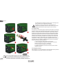
2.2 - +RUL]RQWDO&RQ¿JXUDWLRQ
Remove the 4 support feet from the bottom tray of the packaging and
screw them fully into their brass seats on face E. Put the system in place,
taking into account the dimensions in Fig.10.
7KHGLVWDQFHRIDWOHDVWPPEHWZHHQ)DFH%RIWKHV\VWHP
and an obstruction is recommended so as to be able to carry out
maintenance on the non-return valve without disconnecting the
system.
7KHGLVWDQFHRIDWOHDVWPPEHWZHHQ)DFH$RIWKHV\VWHP
and an obstruction is recommended so as to be able to remove
the door and gain access to the technical compartment.
7KHGLVWDQFHRIDWOHDVWPPEHWZHHQ)DFH'RIWKHV\VWHP
and an obstruction is obligatory to let out the power supply cable.
,IWKHVXUIDFHLVQRWÀDWXQVFUHZWKHIRRWWKDWLVQRWWRXFKLQJDQGDGMXVW
its height until it contacts the surface so as to ensure the stability of the
system. The system must in fact be placed in a safe and stable position,
ensuring that its axis is vertical: it must not be in an inclined position.
2.2.1 Hydraulic connections
Make the connection at input to the system through the mouth on Face C
marked “IN” in Fig.10 (suction connection). Then remove the respective cap
10 mm
200 mm
270 mm
OUT 1
OUT 2
IN
565 mm
370 mm
265 mm
Figure 10

71
71
with the aid of the accessory tool or with a screwdriver.
Make the connection at output from the system through the mouth on Face C
marked “OUT 1” in Fig.10 and/or through the mouth on Face D marked “OUT
´LQ)LJGHOLYHU\FRQQHFWLRQ,QWKLVFRQ¿JXUDWLRQHLWKHURIWKHPRXWKV
can be used as an alternative to the other (depending on the convenience
of the installation), or simultaneously (dual delivery system). So remove the
cap(s) from the door(s) you intend to use with the aid of the accessory tool or
with a screwdriver.
All the hydraulic connections of the system to the plant to which it can be con-
nected are of the threaded female type 1” GAS, made of brass.
See WARNING for Figure 9.
2.2.2 Orientation of the Interface Panel
The Interface Panel has been designed so that it can be oriented in
the direction where it is most convenient for the user to read: its square
shape allows it to be rotated from 90° to 90° (Fig.11).
Figure 11
'LVHQJDJHWKHVFUHZVDWWKHFRUQHUVRIWKHSDQHOXVLQJWKH
hex wrench provided with the accessory tool.
'RQRWUHPRYHWKHVFUHZVMXVWGLVHQJDJHWKHPIURPWKHWKUHDG
on the product body.
%HFDUHIXOQRWWRGURSWKHVFUHZVLQWRWKHV\VWHP
0RYHWKHSDQHODZD\WDNLQJFDUHQRWWRSXOORQWKHVLJQDO
transmission cable
5HSRVLWLRQWKHSDQHOLQLWVVHDWDWWKHSUHIHUUHGDQJOHWDNLQJ
care not to pinch the cable.
7LJKWHQWKHVFUHZVZLWKWKHZUHQFK
ENGLISH
GB

ENGLISH
GB
72
2.2.3 Loading Operation
Installation above head and below head
With reference to its position with respect to the water to be pumped, the
LQVWDOODWLRQRIWKHV\VWHPPD\EHGH¿QHG³DERYHKHDG´RU³EHORZKHDG´,Q
SDUWLFXODUWKHLQVWDOODWLRQLVGH¿QHG³DERYHKHDG´ZKHQWKHSXPSLVSODFHG
at a level higher than the water to be pumped (e.g. pump on the surface and
water in a well); vice versa it is “below head” when the pump is placed at a
level lower than the water to be pumped (e.g. overhead cistern and pump
below).
Installation “above head”: with the aid of the accessory tool (Fig.3_point 5) or
ZLWKDVFUHZGULYHUUHPRYHWKH¿OOLQJFDSZKLFKIRUWKHKRUL]RQWDOFRQ¿JXUD-
tion, is the one on Face F (Fig.1). Fill the system with clean water through the
loading door, taking care to let the air out. The quantity of water with which to
¿OOWKHV\VWHPPXVWEHDWOHDVWOLWUHV,WLVUHFRPPHQGHGWR¿WDQRQUHWXUQ
YDOYHDWWKHHQGRIWKHVXFWLRQSLSHIRRWYDOYHVRDVWREHDEOHWR¿OOLWTXLFNO\
too during the loading operation. In this case the quantity of water necessary
for the loading operation will depend on the length of the suction pipe (1.5
litres + …).
Figure 12
x4
x4
Installation “below head”: if there are no check valves between the water
deposit and the system (or if they are open), it loads automatically as soon as
LWLVDOORZHGWROHWRXWWKHWUDSSHGDLU6RVODFNHQLQJWKH¿OOLQJFDS)DFH)
Fig.3) enough to vent the air allows the system to load completely. To slacken
the cap, use the accessory tool (Fig.3_point 5) or a screwdriver. You must
survey the operation and close the loading door as soon as the water comes
RXWKRZHYHULWLVUHFRPPHQGHGWR¿WDFKHFNYDOYHLQWKHVHFWLRQRIWKH
suction pipe and to use it to control the loading operation with the cap loose).
Alternatively, in the case where the suction pipe is intercepted by a closed
valve, the loading operation may be carried out in a similar way to the one
described for installation over head.
3 - COMMISSIONING
The pressure at pump input must not be higher than 2 bar.
The suction depth must not exceed 8 m.
3.1 - Electrical Connections
To improve immunity to the possible noise radiated towards other appli-
ances it is recommended to use a separate electrical duct to supply the
product.
Attention: always respect the safety regulations!
Electrical installation must be carried out by an expert, autho-
rised electrician, who takes on all responsibility.
The system must be correctly and safely earthed as required by
the regulations in force.
The line voltage may change when the electropump is started.
The line voltage may undergo variations depending on other
devices connected to it and on the quality of the line.

ENGLISH
GB
73
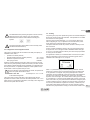
The differential switch protecting the system must be correctly
sized and must be of the “Class A” type. The automatic
differential switch must be marked with the following two
symbols:
The thermal magnetic circuit breaker must be correctly sized
(see Electrical Characteristics)
&RQ¿JXUDWLRQRIWKH,QWHJUDWHG,QYHUWHU
7KHV\VWHPLVFRQ¿JXUHGE\WKHPDQXIDFWXUHUWRVDWLVI\WKHPDMRULW\RI
installation cases, that is:
operation at constant pressure;
Set-Point (desired value of constant pressure): SP = 3.0 bar
Reduction of pressure to restart: RP = 0.3 bar
Anti-cycling function: Disabled
However, all these parameters and many others can be set by the user.
There are many other operating modes and accessory functions. Thanks
WRWKHGLIIHUHQWSRVVLEOHVHWWLQJVDQGWKHDYDLODELOLW\RIFRQ¿JXUDEOHLQSXW
and output channels, it is possible to adapt the inverter operation to the
requirements of various systems. See par. 5-6-7
)RUWKHGH¿QLWLRQRIWKHSDUDPHWHUV63DQG53WKHSUHVVXUHDW
which the system starts has the value:
Pstart = SP – RP For example: 3.0 – 0.3 = 2.7 bar
LQWKHGHIDXOWFRQ¿JXUDWLRQ
The system does not work if the utility is at a height higher than the
equivalent in metres of water column of the Pstart (consider 1 bar = 10 m
ZDWHUFROXPQIRUWKHGHIDXOWFRQ¿JXUDWLRQLIWKHXWLOLW\LVDWDKHLJKWRIDW
least 27m the system does not start.
3.3 - Priming
The priming of a pump is the phase during which the machine attempts to
¿OOWKHERG\DQGWKHVXFWLRQSLSHZLWKZDWHU,IWKHRSHUDWLRQLVVXFFHVVIXO
the machine can work regularly.
2QFHWKHSXPSKDVEHHQ¿OOHGSDUDQGWKHGHYLFHKDV
EHHQFRQ¿JXUHGSDULWLVSRVVLEOHWRFRQQHFWWKHHOHFWULFSRZHU
supply after having opened at least one utility on delivery.
The system starts and checks the presence of water in delivery for the
¿UVWVHFRQGV
,IDÀRZRIZDWHULVGHWHFWHGLQGHOLYHU\WKHSXPSLVSULPHGDQGVWDUWV
its regular work. This is the typical case of installation below head (par.
2.1.2, 2.2.3). The utility opened in delivery from which the pumped water
is coming out can be closed.
,IDUHJXODUÀRZLQGHOLYHU\LVQRWGHWHFWHGDIWHUVHFRQGVWKHV\VWHP
DVNVIRUFRQ¿UPDWLRQWRHQWHUWKHSULPLQJSURFHGXUHW\SLFDOFDVHRI
installation above head par. 2.1.2, 2.2.3). Or:
When “+” is pressed the pump enters the priming procedure: it starts
working for a maximum time of 5 minutes during which the safety block
for dry operation is not tripped. The priming time depends on various
SDUDPHWHUVWKHPRVWLQÀXHQWLDORIZKLFKDUHWKHGHSWKRIWKHZDWHUOHYHO
from which it is drawing, the diameter of the suction pipe, the water-
tightness of the suction pipe. On condition that a suction pipe is used that
is no smaller than 1” and that it is well sealed (with no holes or joins from
which it can take in air), the product has been studied to manage to prime
in water conditions up to 8m in depth in a time of less than 5 minutes. As
VRRQDVWKHSURGXFWGHWHFWVDUHJXODUÀRZLQGHOLYHU\LWOHDYHVWKHSULP-
ing procedure and starts its regular work. The utility opened in delivery
from which the pumped water is coming out can be closed. If after 5 min-

ENGLISH
GB
74
utes of the procedure the product is still not primed, the interface display
sends a failure message. Disconnect the power supply, load the product
adding new water, wait 10 minutes and repeat the procedure from the
moment you put the plug in the socket.
3UHVV³³WRFRQ¿UPWKDW\RXGRQRWZDQWWRVWDUWWKHSULPLQJSURFHGXUH
The product remains in alarm status
Operation
Once the electropump is primed, the system starts regular operation ac-
FRUGLQJWRWKHFRQ¿JXUHGSDUDPHWHUVLWVWDUWVDXWRPDWLFDOO\ZKHQWKHWDS
is turned on, supplies water at the set pressure (SP), keeps the pressure
constant even when other taps are turned on, stops automatically after
time T2 once the switching off conditions are reached (T2 can be set by
the user, factory value 10 sec).
4 - PROTECTION SYSTEMS
IThe device is equipped with protection systems to preserve the pump,
the motor, the supply line and the inverter. If one or more protections trip,
WKHRQHZLWKWKHKLJKHVWSULRULW\LVLPPHGLDWHO\QRWL¿HGRQWKHGLVSOD\
Depending on the type of error the motor may stop, but when normal
conditions are restored the error status may be cancelled immediately or
only after a certain time, following an automatic reset.
In the case of blockage due to water lack (BL), blockage due to motor
overload (OC), blockage, blockage due to direct short circuit between
the motor phases (SC), you can try to exit the error conditions manually
by simultaneously pressing and releasing the + and – keys. If the error
condition remains, you must take steps to eliminate the cause of the fault.
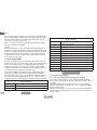
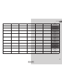
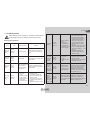
Alarm in the fault log
Display indication Description
PD Irregular switching off
FA Problems in the cooling system
Table 1: Alarms
Blockage conditions
Display indication Description
BL Blockage due to water lack
BP1 Blockage due to reading error on the internal pressure sensor
BP2 Blockage due to reading error on the remote pressure sensor
PB %ORFNDJHGXHWRVXSSO\YROWDJHRXWVLGHVSHFL¿FDWLRQV
OT Blockage due to overheating of the power stages
OC Blockage due to motor overload
SC Blockage due to short circuit between the motor phases
ESC Blockage due to short circuit to earth
PB Blockage due to abnormal voltage
NC Blockage due to motor disconnected
Ei Blockage due to i-th internal error
Vi Blockage due to i-th internal voltage out of tolerance
4.1 - Description of blockages
4.1.1 - “BL” Anti Dry-Run (Protection against dry running)
In the case of lack of water the pump is stopped automatically after the
time TB. This is indicated by the red “Alarm” led and by the letters “BL” on
the display.
$IWHUKDYLQJUHVWRUHGWKHFRUUHFWÀRZRIZDWHU\RXFDQWU\WROHDYHWKH
protective block manually by pressing the “+” and “-“ keys simultaneously
and then releasing them.
If the alarm status remains, or if the user does not intervene by restoring
WKHÀRZRIZDWHUDQGUHVHWWLQJWKHSXPSWKHDXWRPDWLFUHVWDUWZLOOWU\WR
restart the pump.
Table 2: Indications of blockages

75
75
If the parameter SP is not correctly set, the protection against
water lack may not work correctly.
4.1.2 - Anti-Cycling (Protection against continuous cycles without
utility request)
If there are leaks in the delivery section of the plant, the system starts
and stops cyclically even if no water is intentionally being drawn: even
just a slight leak (a few ml) can cause a fall in pressure which in turn
starts the electropump.
The electronic control of the system is able to detect the presence of the
leak, based on its recurrence.
The Anti-Cycling function can be excluded or activated in Basic or Smart
mode (par 7.7.5).
In Basic mode, once the condition of recurrence is detected the pump
stops and remains waiting to be manually reset. This condition is commu-
nicated to the user by the lighting of the red “Alarm” led and the appear-
ance of the word “ANTICYCLING” on the display. After the leak has been
removed, you can manually force restart by simultaneously pressing and
releasing the “+” and “-“ keys.
In Smart mode, once the leak condition is detected, the parameter RP is
increased to decrease the number of starts over time.
4.1.3 - Anti-Freeze (Protection against freezing of water in the sys-
tem)
The change of state of water from liquid to solid involves an increase
in volume. It is therefore essential to ensure that the system does not
remain full of water with temperatures close to freezing point, to avoid
breakages of the system. This is the reason why it is recommended to
empty any electropump that is going to remain unused during the winter.
However, this system has a protection that prevents ice formation inside
by activating the electropump when the temperature falls to values close
to freezing point. In this way the water inside is heated and freezing
prevented.
The Anti-Freeze protection works only if the system is regularly
fed: with the plug disconnected or in the absence of current the
protection cannot work.
However, it is advised not to leave the system full during long
periods of inactivity: drain the system accurately through the
drainage cap (Fig.1 Face E) and put it away in a sheltered place.
4.1.4 - “BP1” Blockage due to fault of the internal pressure sensor
If the device detects a fault in the pressure sensor the pump remains
blocked and the error signal “BP1” is given. This status begins as soon as
the problem is detected and ends automatically when correct conditions
have been restored.
4.1.5 - “BP2” Blockage due to reading error on the remote pressure
sensor
BP2 indicates a warning on the remote pressure sensor connected to the
I/O control unit.
³3%´%ORFNDJHGXHWRVXSSO\YROWDJHRXWVLGHVSHFL¿FDWLRQV
This occurs when the allowed line voltage at the supply terminal assumes
YDOXHVRXWVLGHWKHVSHFL¿FDWLRQV,WLVUHVHWRQO\DXWRPDWLFDOO\ZKHQWKH
voltage at the terminal returns within the allowed values.
4.1.7 - “SC” Blockage due to short circuit between the motor phases
The device is provided with protection against the direct short circuit
which may occur between the motor phases. When this blockage is
indicated you can attempt to restore operation by simultaneously holding
down the + and – keys, but this will not have any effect until 10 seconds
have passed since the moment the short circuit occurred.
4.2 - Manual reset of error conditions
In error status, the user can cancel the error by forcing a new attempt,
pressing and then releasing the + and – keys.
ENGLISH
GB
La page est en cours de chargement...
La page est en cours de chargement...
La page est en cours de chargement...
La page est en cours de chargement...
La page est en cours de chargement...
La page est en cours de chargement...
La page est en cours de chargement...
La page est en cours de chargement...
La page est en cours de chargement...
La page est en cours de chargement...
La page est en cours de chargement...
La page est en cours de chargement...
La page est en cours de chargement...
La page est en cours de chargement...
La page est en cours de chargement...
La page est en cours de chargement...
La page est en cours de chargement...
La page est en cours de chargement...
La page est en cours de chargement...
La page est en cours de chargement...
La page est en cours de chargement...
La page est en cours de chargement...
La page est en cours de chargement...
La page est en cours de chargement...
La page est en cours de chargement...
La page est en cours de chargement...
La page est en cours de chargement...
La page est en cours de chargement...
La page est en cours de chargement...
La page est en cours de chargement...
La page est en cours de chargement...
La page est en cours de chargement...
La page est en cours de chargement...
La page est en cours de chargement...
La page est en cours de chargement...
La page est en cours de chargement...
La page est en cours de chargement...
-
 1
1
-
 2
2
-
 3
3
-
 4
4
-
 5
5
-
 6
6
-
 7
7
-
 8
8
-
 9
9
-
 10
10
-
 11
11
-
 12
12
-
 13
13
-
 14
14
-
 15
15
-
 16
16
-
 17
17
-
 18
18
-
 19
19
-
 20
20
-
 21
21
-
 22
22
-
 23
23
-
 24
24
-
 25
25
-
 26
26
-
 27
27
-
 28
28
-
 29
29
-
 30
30
-
 31
31
-
 32
32
-
 33
33
-
 34
34
-
 35
35
-
 36
36
-
 37
37
-
 38
38
-
 39
39
-
 40
40
-
 41
41
-
 42
42
-
 43
43
-
 44
44
-
 45
45
-
 46
46
-
 47
47
-
 48
48
-
 49
49
-
 50
50
-
 51
51
-
 52
52
-
 53
53
-
 54
54
-
 55
55
-
 56
56
-
 57
57


DAB DAB E.SYBOX Instruction For Installation And Maintenance
- Taper
- Instruction For Installation And Maintenance
dans d''autres langues
- English: DAB DAB E.SYBOX
Documents connexes
Autres documents
-
Stoelting VB35/VB60/VB80/VB90/VB120/VB160 Manuel utilisateur
-
York Web-enabled Central Controller Guide d'installation
-
Nobles Scout 7 Mode d'emploi
-
Raypak XVers L 406L-856L Type H Mode d'emploi
-
REMEHA Fusion and Fusion Hybrid Mode d'emploi
-
Bradford White BMGH1600 Manuel utilisateur
-
AEG BS7304001M Guide d'installation
-
-
GEAppliances PFE28RSH Technical Service Manual
-
Stanley HP210 HYDRAULIC POWER UNIT Manuel utilisateur