Allen-Bradley MicroLogix 1200 Installation Instructions Manual
- Taper
- Installation Instructions Manual

Publication 1762-IN016A-EN-P - July 2003
Installation Instructions
MicroLogix™ 1200 Analog Output Module
(Catalog Number 1762-OF4)
Inside…
For More Information................................................................................2
Description................................................................................................3
Installation ................................................................................................3
Mounting...................................................................................................5
System Assembly......................................................................................7
Field Wiring Connections..........................................................................7
Output Type Selection...............................................................................8
Wiring .......................................................................................................8
I/O Memory Mapping .............................................................................11
Specifications .........................................................................................16
Hazardous Location Considerations .......................................................18
Environnements dangereux ....................................................................19
AB Spares

2 MicroLogix™ 1200 Analog Output Module
Publication 1762-IN016A-EN-P - July 2003
For More Information
If you would like a manual, you can:
• download a free electronic version from the internet:
www.ab.com/micrologix or www.theautomationbookstore.com
• purchase a printed manual by:
– contacting your local distributor or Rockwell Automation representative
– visiting www.theautomationbookstore.com and placing your order
– calling 1.800.963.9548 (USA/Canada)
or 001.330.725.1574 (Outside USA/Canada)
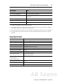
For Refer to this Document Pub. No.
Information on installing, wiring, and operating a
MicroLogix 1200 Programmable Controller
MicroLogix 1200 Programmable
Controllers User Manual
1762-UM001
Installation guide for the MicroLogix 1200
Programmable Controller.
MicroLogix 1200 Programmable
Controllers Installation Instructions
1762-IN006
Installation guide for the MicroLogix 1200 Memory
Module and Real Time clock.
MicroLogix 1200 Memory Module and/or
Real Time Clock Installation Instructions
1762-IN001
More information on proper wiring and grounding
techniques.
Industrial Automation Wiring and
Grounding Guidelines
1770-4.1

MicroLogix™ 1200 Analog Output Module 3
Publication 1762-IN016A-EN-P - July 2003
Description
Installation
1762 I/O is suitable for use in an industrial environment when installed in accordance with
these instructions. Specifically, this equipment is intended for use in clean, dry environments
(Pollution degree 2
(1)
) and to circuits not exceeding Over Voltage Category II
(2)
(IEC
60664-1).
(3)
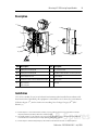
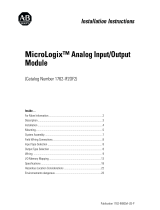
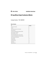
Item Description Item Description
1a upper panel mounting tab 5 bus connector cover
1b lower panel mounting tab 6 flat ribbon cable with bus connector (female)
2 power diagnostic LED 7 terminal block
3 module door with terminal identification label 8 DIN rail latch
4 bus connector
with male pins
9 pull loop
(1) Pollution Degree 2 is an environment where, normally, only non-conductive pollution occurs except that occasionally a
temporary conductivity caused by condensation shall be expected.
(2) Over Voltage Category II is the load level section of the electrical distribution system. At this level transient voltages are
controlled and do not exceed the impulse voltage capability of the product’s insulation.
(3) Pollution Degree 2 and Over Voltage Category II are International Electrotechnical Commission (IEC) designations.
1a
1b
5
2
3
9
4
6
7
1a
1b
2
6
8
AB Spares

4 MicroLogix™ 1200 Analog Output Module
Publication 1762-IN016A-EN-P - July 2003
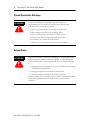
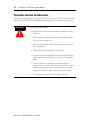
Prevent Electrostatic Discharge
Remove Power
ATTENTION
!
Electrostatic discharge can damage integrated circuits or
semiconductors if you touch bus connector pins. Follow these
guidelines when you handle the module:
• Touch a grounded object to discharge static potential.
• Wear an approved wrist-strap grounding device.
• Do not touch the bus connector or connector pins.
• Do not touch circuit components inside the module.
• If available, use a static-safe work station.
• When not in use, keep the module in its static-shield box.
ATTENTION
!
Remove power before removing or installing this module. When you
remove or install a module with power applied, an electrical arc may
occur. An electrical arc can cause personal injury or property damage
by:
• sending an erroneous signal to your system’s field devices, causing
unintended machine motion
• causing an explosion in a hazardous environment
• causing permanent damage to the module’s circuitry
Electrical arcing causes excessive wear to contacts on both the module
and its mating connector. Worn contacts may create electrical
resistance.

MicroLogix™ 1200 Analog Output Module 5
Publication 1762-IN016A-EN-P - July 2003
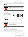
Mounting
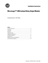
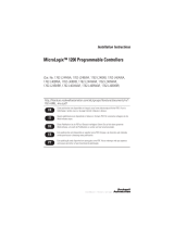
Minimum Spacing
Maintain spacing from enclosure
walls, wireways, adjacent
equipment, etc. Allow 50.8 mm
(2 in.) of space on all sides for
adequate ventilation, as shown:
.
DIN Rail Mounting
The module can be mounted using the following DIN rails: 35 x 7.5 mm
(EN 50 022 - 35 x 7.5) or 35 x 15 mm (EN 50 022 - 35 x 15).
Before mounting the module on a DIN rail, close the DIN rail latch. Press the DIN rail
mounting area of the module against the DIN rail. The latch will momentarily open and lock
into place.
ATTENTION
!
Do not remove protective debris strip until after the module and all
other equipment near the module is mounted and wiring is complete.
Once wiring is complete and the module is free of debris, carefully
remove protective debris strip. Failure to remove strip before operating
can cause overheating.
TIP
1762 expansion I/O may be mounted horizontally only.
ATTENTION
!
During panel or DIN rail mounting of all devices, be sure that all
debris (metal chips, wire strands, etc.) is kept from falling into the
module. Debris that falls into the module could cause damage when
power is applied to the module.
Side
Side
Top
Bottom
MicroLogix
1200
1762 I/O
1762 I/O
1762 I/O
AB Spares

6 MicroLogix™ 1200 Analog Output Module
Publication 1762-IN016A-EN-P - July 2003
Use DIN rail end anchors (Allen-Bradley part number 1492-EA35 or 1492-EAH35) for
environments with vibration or shock concerns.
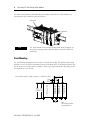
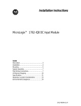
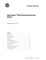
Panel Mounting
Use the dimensional template shown below to mount the module. The preferred mounting
method is to use two M4 or #8 panhead screws per module. M3.5 or #6 panhead screws may
also be used, but a washer may be needed to ensure a good ground contact. Mounting screws
are required on every module.
TIP
For environments with extreme vibration and shock concerns, use
the panel mounting method described below, instead of DIN rail
mounting.
End Anchor
End Anchor
90
(3.54)
100
(3.94)
40.4
(1.59)
40.4
(1.59)
14.5
(0.57)
For more than 2 modules: (number of modules - 1) x 40.4 mm (1.59 in.)
NOTE:
Hole spacing tolerance:
±0.4 mm (0.016 in.).
MicroLogix 1200
Expansion I/O
MicroLogix 1200
Expansion I/O
MicroLogix 1200
Expansion I/O
MicroLogix 1200

MicroLogix™ 1200 Analog Output Module 7
Publication 1762-IN016A-EN-P - July 2003
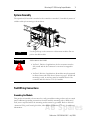
System Assembly
The expansion I/O module is attached to the controller or another I/O module by means of
a ribbon cable after mounting as shown below.
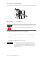
Field Wiring Connections
Grounding the Module
This product is intended to be mounted to a well-grounded mounting surface such as a metal
panel. Additional grounding connections from the module’s mounting tabs or DIN rail (if
used) are not required unless the mounting surface cannot be grounded. Refer to Industrial
Automation Wiring and Grounding Guidelines, Allen-Bradley publication 1770-4.1, for additional
information.
TIP
Use the pull loop on the connector to disconnect modules. Do not
pull on the ribbon cable.
!
WARNING
EXPLOSION HAZARD
• In Class I, Division 2 applications, the bus connector must be
fully seated and the bus connector cover must be snapped in
place.
• In Class I, Division 2 applications, all modules must be mounted
in direct contact with each other as shown on page 5. If DIN rail
mounting is used, an end stop must be installed ahead of the
controller and after the last 1762 I/O module.
AB Spares

8 MicroLogix™ 1200 Analog Output Module
Publication 1762-IN016A-EN-P - July 2003
Output Type Selection
The output type selection, current or voltage, is made by wiring to the appropriate terminals,
Iout or Vout, and by the type/range selection bits in the Configuration Data File (see
page 14).
Wiring
System Wiring Guidelines
Consider the following when wiring your system:
• The analog common (COM) is not connected to earth ground inside the module. All
terminals are electrically isolated from the system.
• Channels are not isolated from each other.
• Use Belden™ 8761, or equivalent, shielded wire.
• Under normal conditions, the drain wire (shield) should be connected to the metal
mounting panel (earth ground). Keep shield connection to earth ground as short as
possible.
• To ensure optimum accuracy for voltage type outputs, limit overall cable impedance
by keeping all analog cables as short as possible. Locate the I/O system as close to
your voltage type sensors or actuators as possible.
ATTENTION
!
Analog outputs may fluctuate for less than a second when power is
applied or removed. This characteristic is common to most analog
outputs. While the majority of loads will not recognize this short
signal, it is recommended that preventive measures be taken to
ensure that connected equipment is not affected.

MicroLogix™ 1200 Analog Output Module 9
Publication 1762-IN016A-EN-P - July 2003
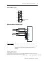
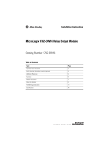
Terminal Block Layout
Differential Sensor Transmitter Types
Labeling the Terminals
A write-on label is provided with the module. Mark the identification of each terminal with
permanent ink, and slide the label back into the door.
TIP
Grounding the cable shield at the module end only usually provides
sufficient noise immunity. However, for best cable shield
performance, earth ground the shield at both ends, using a 0.01 µF
capacitor at one end to block AC power ground currents, if
necessary.
V out 3
V out 2
V out 1
V out 0
I out 3
I out 2
I out 1
I out 0
COM
COM
Commons connected
internally.
I out 0
I out 1
V out 2
V out 3
V out 0
V out 1
COM
I out 3
I out 2
COM
Current Load
Voltage Load
AB Spares

10 MicroLogix™ 1200 Analog Output Module
Publication 1762-IN016A-EN-P - July 2003
Wiring the Finger-Safe Terminal Block
When wiring the terminal block, keep the finger-safe cover in place.
1. Route the wire under the terminal pressure plate. You can use the stripped end of the
wire or a spade lug. The terminals will accept a 6.35 mm (0.25 in.) spade lug.
2. Tighten the terminal screw making sure the pressure plate secures the wire.
Recommended torque when tightening terminal screws is 0.904 Nm (8 in-lbs).
3. After wiring is complete, remove the debris shield.
ATTENTION
!
Be careful when stripping wires. Wire fragments that fall into a
module could cause damage when power is applied. Once wiring is
complete, ensure the module is free of all metal fragments.
TIP
If you need to remove the finger-safe cover, insert a screw driver
into one of the square wiring holes and gently pry the cover off. If
you wire the terminal block with the finger-safe cover removed, you
will not be able to put it back on the terminal block because the
wires will be in the way.

MicroLogix™ 1200 Analog Output Module 11
Publication 1762-IN016A-EN-P - July 2003
Wire Size and Terminal Screw Torque
Each terminal accepts up to two wires with the following restrictions:
I/O Memory Mapping
A
ddressing
The addressing scheme for 1762-OF4 is shown below.
(1) I/O located on the controller (embedded I/O) is slot 0. I/O added to the controller (expansion I/O) begins with slot 1.
Wire Type Wire Size Terminal Screw Torque
Solid Cu-90°C (194°F) #14 to #22 AWG 0.904 Nm (8 in-lbs)
Stranded Cu-90°C (194°F) #16 to #22 AWG 0.904 Nm (8 in-lbs)
O0:x.0/0
Output (O) File
Output Data File (0)
Slot Number
(1)
Word
Bit
Bit Delimiter
Word Delimiter
Slot Delimiter
AB Spares

12 MicroLogix™ 1200 Analog Output Module
Publication 1762-IN016A-EN-P - July 2003
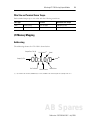
Input Data File
For each module, slot x, words 0 and 1 contain the analog output module status data for use
in the control program.
The bits are defined as follows:
• SOx = General status bits for output channels 0 through 3. This bit is set when an
error (over- or under-range) exists for that channel, or there is a general module
hardware error.
• OOx = Over-range flag bits for output channels 0 through 3. These bits indicate an
input signal above the user range and can be used in the control program for error
detection. The module continues to convert analog data to the maximum full range
value while this bit is set (1). The bit is reset (0) when the error clears.
• UOx = Under-range flag bits for output channels 0 through 3. These bits indicate an
input signal below the user range. They can be used in the control program for error
detection. The module continues to convert analog data to the minimum full range
value while this bit is set (1). The bit is reset (0) when the error clears.
Word
Bit Position
15 14 13 12 11 10 9 8 7 6 5 4 3 2 1 0
0 Reserved SO3 SO2 SO1 SO0
1 Reserved UO0 OO0 UO1 OO1 UO2 OO2 UO3 OO3

MicroLogix™ 1200 Analog Output Module 13
Publication 1762-IN016A-EN-P - July 2003
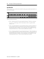
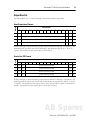
Output Data File
For each module, slot x, words 0 through 3 contain the channel output data.
Words 0 through 3 contain the analog output data for channels 0 through 3, respectively. The
module ignores the “don’t care” bits (0 through 2), but checks the sign bit (15). If bit 15
equals 1, the module sets the output value to 0V or 0 mA.
Words 0 through 3 contain the analog output data for channels 0 through 3, respectively. The
module ignores the “don’t care” bits (0 and 1), but checks the sign bit (15), and bit 14. If bit
15 equals 1, the module sets the output value to 0V or 0 mA. If bit 15 equals zero and bit 14
equals 1, the module sets the output value to 10.5V dc or 21 mA.
Raw/Proportional Format
Word
Bit Position
15 14 13 12 11 10 9 8 7 6 5 4 3 2 1 0
0 0 Channel 0 Data 0 to 32,760 0 0 0
1 0 Channel 1 Data 0 to 32,760 0 0 0
2 0 Channel 2 Data 0 to 32,760 0 0 0
3 0 Channel 3 Data 0 to 32,760 0 0 0
Scaled-for-PID Format
Word
Bit Position
15 14 13 12 11 10 9 8 7 6 5 4 3 2 1 0
0 0 0 Channel 0 Data 0 to 16,380 0 0
1 0 0 Channel 1 Data 0 to 16,380 0 0
2 0 0 Channel 2 Data 0 to 16,380 0 0
3 0 0 Channel 3 Data 0 to 16,380 0 0
AB Spares

14 MicroLogix™ 1200 Analog Output Module
Publication 1762-IN016A-EN-P - July 2003
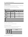
Configuration Data File
The configuration of the format for analog outputs is made at going to run (GTR). Changes
made to the configuration file while in run mode have no effect.
The configuration table for analog outputs is shown in the table below.
Bit 15 and Bits 7 through 0 - Reserved
These bits are reserved and are not checked by the module.
Data Format (Bits 14 through 12)
These bits indicate the format of the data as shown in the following table. Other
combinations of these bits are not supported and result in an error.
Configuration Data File
Word
Bit Position
1514131211109876543210
0
reserved
Data Format
Output Channel 0
Type/Range Select
Output Channel 0
reserved
1
Data Format
Output Channel 1
Type/Range Select
Output Channel 1
reserved
2
Data Format
Output Channel 2
Type/Range Select
Output Channel 2
reserved
3
Data Format
Output Channel 3
Type/Range Select
Output Channel 3
reserved
4reserved
5reserved
6reserved
7reserved
Bit Settings
Data Format
14 13 12
0 0 0 Raw/Proportional
0 1 0 Scaled for PID
other Not Supported

MicroLogix™ 1200 Analog Output Module 15
Publication 1762-IN016A-EN-P - July 2003
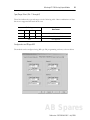
Type/Range Select (Bits 11 through 8)
These bits indicate the type and range as in the following table. Other combinations of these
bits are not supported and result in an error.
Configuration via RSLogix 500
The module can be configured using RSLogix 500 programming software, as shown below.
Bit Settings
Data Format
11 10 9 8
0 0 0 0 Voltage Mode 0 to 10V dc
0 0 1 1 Current Mode 4 to 20 mA
other Not Supported
AB Spares

16 MicroLogix™ 1200 Analog Output Module
Publication 1762-IN016A-EN-P - July 2003
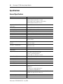
Specifications
General Specifications
Specification Value
Dimensions 90 mm (height) x 87 mm (depth) x 40 mm (width)
height including mounting tabs is 110 mm
3.54 in. (height) x 3.43 in. (depth) x 1.58 in. (width)
height including mounting tabs is 4.33 in.
Approximate Shipping Weight
(with carton)
235 g (0.517 lbs.)
Storage Temperature -40°C to +85°C (-40°F to +185°F)
Operating Temperature 0°C to +55°C (-32°F to +131°F)
Operating Humidity 5% to 95% non-condensing
Operating Altitude 2000 meters (6561 feet)
Vibration Operating: 10 to 500 Hz, 5G, 0.030 in. max. peak-to-peak
Shock Operating: 30G
Bus Current Draw (max.) 40 mA at 5V dc
165 mA at 24V dc
Analog Normal Operating Range
(bipolar)
Voltage: 0 to 10V dc
Current: 4 to 20 mA
Full Scale
(1)
Analog Ranges
Voltage: 0 to 10.5V dc
Current: 0 to 21 mA
Resolution 12 bits (unipolar)
Repeatability
(2)
±0.1%
Output Group to System Isolation
30V ac/30V dc rated working voltage
(3)
(IEC Class 2 reinforced insulation)
type test: 500V ac or 707V dc for 1 minute
Module Power LED On: indicates power is applied.
Recommended Cable Belden™ 8761 (shielded)
Vendor I.D. Code 1
Product Type Code 10
Product Code 66
Agency Certification C-UL certified (under CSA C22.2 No. 142)
UL 508 listed
CE compliant for all applicable directives
C-Tick marked for all applicable acts
Hazardous Environment Class Class I, Division 2, Hazardous Location, Groups A, B, C, D
(UL 1604, C-UL under CSA C22.2 No. 213)
Noise Immunity NEMA standard ICS 2-230
Radiated and Conducted Emissions EN50081-2 Class A

MicroLogix™ 1200 Analog Output Module 17
Publication 1762-IN016A-EN-P - July 2003
Output Specifications
Electrical /EMC: The module has passed testing at the following levels:
ESD Immunity (EN61000-4-2) 4 kV contact, 8 kV air, 4 kV indirect
Radiated Immunity (EN61000-4-3) 10 V/m, 80 to 1000 MHz, 80% amplitude modulation, +900 MHz
keyed carrier
Fast Transient Burst (EN61000-4-4) 2 kV, 5 kHz
Surge Immunity (EN61000-4-5) 1 kV galvanic gun
Conducted Immunity (EN61000-4-6)
10V, 0.15 to 80 MHz
(4)
(1) The over- or under-range flag comes on when the normal operating range (over/under) is exceeded. The module continues to
convert the analog output up to the maximum full scale range.
(2) Repeatability is the ability of the output module to reproduce output reading when the same controller value is applied to it
consecutively, under the same conditions and in the same direction.
(3) Rated working voltage is the maximum continuous voltage that can be applied at the terminals with respect to earth ground.
(4) Conducted Immunity frequency range may be 150 kHz to 30 MHz if the Radiated Immunity frequency range is 30 MHz to
1000 MHz.
Specification Value
Number of Outputs 4 single-ended (bipolar)
D/A Converter Type R-2R Ladder Voltage Switching
Module Update Time 2.5 ms
Resistive Load on Current Output 0 to 500 Ω (includes wire resistance)
Load Range on Voltage Output > 1KΩ
Reactive Load, Current Output < 0.1 mH
Reactive Load, Voltage Output < 1 µF
Typical Overall Accuracy
(1)
(1) Includes offset, gain, non-linearity and repeatability error terms.
±1% full scale at 0 to 55°C
±0.5% full scale at 25°C
Output Ripple
range 0 to 500 Hz
(referred to output range)
< ±0.1%
Non-linearity (in percent full scale) < ±0.5%
Open and Short-Circuit Protection Continuous
Output Protection ±32 mA
Specification Value
AB Spares

18 MicroLogix™ 1200 Analog Output Module
Publication 1762-IN016A-EN-P - July 2003
Hazardous Location Considerations
This equipment is suitable for use in Class I, Division 2, Groups A, B, C, D or non-hazardous
locations only. The following WARNING statement applies to use in hazardous locations.
!
WARNING
\
EXPLOSION HAZARD
• Substitution of components may impair suitability for Class I,
Division 2.
• Do not replace components or disconnect equipment unless
power has been switched off.
• Do not connect or disconnect components unless power has
been switched off.
• This product must be installed in an enclosure.
• In Class I, Division 2 applications, the bus connector must be
fully seated and the bus connector cover must be snapped in
place.
• In Class I, Division 2 applications, all modules must be
mounted in direct contact with each other as shown on page 5.
If DIN rail mounting is used, an end stop must be installed
ahead of the controller and after the last 1762 I/O module.
• All wiring must comply with N.E.C. article 501-4(b).

MicroLogix™ 1200 Analog Output Module 19
Publication 1762-IN016A-EN-P - July 2003
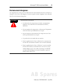
Environnements dangereux
Cet équipement est conçu pour être utilisé dans des environnements de Classe 1, Division 2,
Groupes A, B, C, D ou non dangereux. La mise en garde suivante s’applique à une utilisation
dans des environnements dangereux.
!
AVERTISSEMENT
DANGER D’EXPLOSION
• La substitution de composants peut rendre cet équipement
impropre à une utilisation en environnement de Classe 1,
Division 2.
• Ne pas remplacer de composants ou déconnecter l'équipement
sans s'être assuré que l'alimentation est coupée.
• Ne pas connecter ou déconnecter des composants sans s'être
assuré que l'alimentation est coupée.
• Ce produit doit être installé dans une armoire.
• Pour les applications de Classe I, Division 2, le connecteur de
bus doit être correctement installé et son couvercle enclenché.
• Pour les applications de Classe 1, Division 2, tous les modules
doivent être installés en contact direct les uns avec les autres,
comme indiqué page 5. Si on utilise le montage sur rail DIN,
une butée doit être placée à l'avant de l'automate et après la
dernière unité d'E/S 1762.
AB Spares

´H'54!¶1•¨
Publication 1762-IN016A-EN-P - July 2003 PN 40072-120-01(1)
Copyright © 2003 Rockwell Automation, Inc. All rights reserved. Printed in the U.S.A.
-
 1
1
-
 2
2
-
 3
3
-
 4
4
-
 5
5
-
 6
6
-
 7
7
-
 8
8
-
 9
9
-
 10
10
-
 11
11
-
 12
12
-
 13
13
-
 14
14
-
 15
15
-
 16
16
-
 17
17
-
 18
18
-
 19
19
-
 20
20


Allen-Bradley MicroLogix 1200 Installation Instructions Manual
- Taper
- Installation Instructions Manual
dans d''autres langues
- English: Allen-Bradley MicroLogix 1200
Documents connexes
-
 Allen-Bradley MicroLogix 1200 Installation Instructions Manual
-
 Allen-Bradley MicroLogix 1762-IF2OF2 Installation Instructions Manual
-
 Allen-Bradley MicroLogix 1200 Installation Instructions Manual
-
 Allen-Bradley MicroLogix 1762-IQ8 Installation Instructions Manual
-
 Allen-Bradley 1762-IQ8OW6 Installation Instructions Manual
-
 Allen-Bradley MicroLogix 1762-OW Installation Instructions Manual


Autres documents
-
Spectrum Controls 1762sc-IF4OF4 Mode d'emploi
-
 Rockwell Automation MicroLogix 1200 Installation Instructions Manual
-
 Rockwell Automation MicroLogix 1200 Installation Instructions Manual
-
 Rockwell Automation Allen-Bradley MicroLogix 1762-OW16 Installation Instructions Manual
-
Rockwell Automation 1766-L32BXBA Installation Instructions Manual
-
Pepperl+Fuchs VBG-PN-K30-DMD-S32-EV Guide d'installation


