
Documentazione
Tecnica
26
rev. 6.1
12/2002
©
CAME
CANCELLI
AUTOMATICI
119G26
G 6000 / G 6001
CANCELLI AUTOMATICI
SERIE GARD |
GARD SERIES
|
SÉRIE GARD |
BAUREIHE GARD
|
SERIE GARD
1. Gruppo GARD
2. Quadro comando
Accessori
3. Asta in alluminio
4. Strisce rosse
fosforescenti
5. Antenna
6. Gomma protettiva
7. Lampade di segnala-
zione
8. Lampeggiatore di
movimento
9. Selettore a chiave
10. Batteria di emergenza
11. Colonnina per
fotocellule
12. Fotocellule di sicurez-
za
13. Colonnina per lettore
magnetico
14. Lettore magnetico
15. Appoggio fisso
16. Sensore magnetico
1. GARD unit
2. Control panel
Accessories
3. Aluminum barrier
4. Red phosphorescent
strips
5. Antenna
6. Anti-collision rubber
7. Movement indicator
lights
8. Flashing movement
warrning light
9. Key-operated selector
switch
10. Emergency battery
11. Photocell Column
12. Safety photocells
13. Column for magnetic
card
reader
14. Magnetic card reader
15. Fixed barrier support
16. Magnetic sensor
1. Groupe GARD
2. Armoire de commande
Accessoires
3. Lisse en aluminium
4. Bandes rouges
phosphorescentes
5. Antenne
6. Boudin caoutchouc
anti-choc
7. Lampe de mouvement
8. Clignotant de
mouvement
9. Sélecteur à clé
10. Batterie d'urgence
11. Colonnette pour
photocellule
12. Photocellule de
sècuritè
13. Colonnette pour
lecteur de carta
magnétique
14. Lecteur de carte
magnétique
15. Appui fixe
16. Capteur magnétique
1. GARD- Bausatz
2. Steuerung Zubehör
3. Aluminium-Stange
4. Rote Phosphoreszenz-
Streifen
5. Antenne
6. Gummi Stoßschutz
7. Bewegungs-
Meldeleuchte
8. Blinkleuchte
9. Schlüsselschalter
10. Notbatterie
11. Photozellen-Säule
12. Sicherheits-Photozelle
13. Magnetkartenleser-
Säule
14. Magnetkartenleser
15. Feste Stütze
16. Magnetischer Sensor
1. Grupo GARD
2. Cuadro de mando
Accesorios
3. Barra de aluminio
4. Bandas roias
fosforescentes
5. Antena
6. Protector de goma
7. Làmpara de
movimiento
8. Làmpara intermitente
de movimiento
9. Selector con Ilave
10. Baterìa de urgencia
11. Columna para
fotocélula
12. Fotocélula de
seguridad
13. Columna para lector
magnético
14. Lector magnético
15. Apoyo fijo
16. Sensor magnético
Automazioni per barriere stradali veloci
Automation systems for swift road barriers
Automatisations pour barrières routieres rapides
Antriebe für Schnell-Schranken
Automatización para barreras viales rápidas
Impianto tipo -
Standard installation -
Installation type
- Standard Montage -
Instalaciòn tipo

- 2 -
Modelli:
G6000
Barriera con motoriduttore irreversibile ali-
mentato a 24V d.c., armadio in acciaio
zincato e verniciato, quadro di controllo e
comando interno.
G6001
Versione con armadio in acciaio inox.
Descrizione:
- Barriera motorizzata adatta alla selezio-
ne di ingressi con passaggio utile fino a
6.5 m. (con accessori fino a 6 m, vedi ta-
bella a pag. 7).
- Progettato e costruito interamente dalla
CAME S.p.A., risponde alle vigenti norme
di sicurezza, con grado di protezione IP
54.
- Garantito 24 mesi salvo manomissioni.
Accessori di completamento:
G0601
Asta in alluminio verniciato bianco sezio-
ne 100x40 mm, L = 6850 mm.
In alternativa
(per zone soggette a forte vento):
G0602 + G0605
Asta in alluminio tubolare verniciato
bianco sez. Ø 100 mm, L = 6850 mm. +
attacco speciale per asta
Attenzione! Controllate che le apparecchiature di comando, di sicurezza e gli accessori siano originali CAME; ciò garantisce e
rende l'impianto di facile esecuzione e manutenzione.
G0603
Gomma protettiva antiurto rossa completa di tappi per asta
G0601.
G0460
Confezione di lampade di segnalazione a 24V con supporti
per aste G0601 e scheda di intermittenza.
G0461
Striscia rosso fosforescente per aste.
G0462
Appoggio fisso per aste.
G0463
Appoggio mobile per aste.
G0465
Rastrelliera in alluminio verniciata per aste.
G0467
Snodo per G0601.
G0468
Supporto per l'applicazione della fotocellula su armadio.
G0469
Supporto per l'applicazione del lampeggiatore su armadio.
ACCESSORI OPZIONALI
Models:
G6000
Barrier with non-reversible, 24 V d.c. gear
motor, case in galvanised steel with
enamel finish, control panel and internal
drive system.
G6001
Version with stainless steel case.
Description:
- This unit can be used to control
entrances up to 6,5 meters wide (with
accessories up to 6 metres, see table on
page 7).
- Designed and constructed entirely by
CAME in compliance with current safety
standards, and with an IP 54 protecting
rating.
- Guaranteed for 24 months, unless
tampered with by unauthorized personnel.
Optional accessories:
G0601
Cross-section 100x40 mm, L = 6850 mm.
aluminium barrier with white enamel
finish.
Alternative system
(for areas subject tstrong winds)
G0602 + G0605
Cross-section Ø 100 mm, L = 6850 mm.
tubolar aluminium barrier with white
enamel finish + special barrier holder.
Attention! to insure easy installation and conformance with current safety norms, we raccomend installation of CAME safety and
control accessories.
G0603
Red anti-collision bumper, complete with endcaps, for G0601
barrier.
G0460
Package of 6 24V signal lamps complete of supports for
G0601 barriers, with flash-control circuit board.
G0461
Red phosphorescent strip for barriers.
G0462
Non-moving support for barriers.
G0463
Moving support for barriers.
G0465
White enameled aluminum fencing for barriers.
G0467
Joint for G0601 barrier.
G0468
Support for attachment of photocell to casings.
G0469
Support for attachment of flashing beacon to casings.
OPTIONAL ACCESSORIES
General specifications
ENGLISH
Caratteristiche generali
ITALIANO

- 3 -
Modèles:
G6000
Barrière avec motoréducteur irréversible
alimenté en 24 V d.c., armoire en acier
galvanisé et verni, tableau de contrôle
ou commande interne.
G6001
Version avec armoire en acier inox.
Description:
- Le groupe est indiqué pour le contrôle
des entrées avec passages jusqu à 6,5
m. (avec accessoires jusqu’à 6 m., voir
tableau p. 7).
- Il a été entièrement concu et construit
par la Société CAME, conformément aux
normes de sécurité en vigueur avec
degré de protection IP 54.
- Il est garanti 24 mois sauf en cas
d'altérations.
Accessoires complémentaires:
G0601
Lisse en aluminium verni blanc section
100x40 mm, L = 6850 mm.
En alternative
(pour les zones sujettes à des vents
forts).
G0602 + G0605
Lisse en aluminium tubulaire verni blanc
section Ø 100 mm, L = 6850 mm. +
fixation spéciale pour lisse.
Attention ! Vérifiez que l’appareillage de commande, de sécurité et les accessoires sont des produits originaux CAME afin de
garantir l’installation et d’en faciliter le montage et l’entretien.
G0603
Coutchouc de protection antichoc rouge comprenant
bouchons pour lisse G0601.
G0460
Ensemble de 6 lampes de signalisation de 24V avec
supports pour lisses G0601 et carte de intermittencie.
G0461
Bande rouge phosphorescente pour lisses.
G0462
Appui fixe pour lisses.
G0463
Appui mobile pour lisses.
G0465
Tablier en aluminium verni pour lisses.
G0467
Articulation pour G0601.
G0468
Support pour l'application d'une photocellule sur l'armoire.
G0469
Support pour l'application du clignotant sur l'armoire.
ACCESSOIRES EN OPTION
Modelle:
G6000
Schranke mit selbsthemmendem 24 V-
Gleichstrom-Getriebemotor, Gehäuse aus
verzinktem und lackiertem Stahl,
eingebaute Motorsteuerung.
G6001
Ausführung mit Edelstahl-Gehäuse.
Beschreibung:
-Die gruppe ist zum Antrieb von
Schranken mit Durchfahrtsbreiten bis
6,5 m. geeignet (mit Zubehör bis 6 m,
siehe Tabelle auf Seite 7).
- Vollkommen von der CAME S.p.A. den
geltenden Sicherheitsnormen
entsprechend entwickelt und
hergestellt. Schutzklasse IP 54.
- Garantie: 24 Monate, vorbehaltlich
unsachgemäßer Handhabung und
Montage.
Zubehör:
G0601
Aluminiumsstange, weiß lacktiert,
schnitt 100x40 mm, L = 6850 mm.
als Alternative
(für Gebiete mit starkem Wind):
G0602 + G0605
Aluminiumrohr-Stange, weiß lacktiert
schnitt Ø 100 mm, L = 6850 mm. +
spezieller Schrankenbaumträger
Achtung! Wir empfehlen original CAME-Schalt- und -Sicherheitsvorrichtungen mit entsprechendem Zubehör zu montieren, um die
einwandfreie Montage und die problemlose Wartung der Anlage zu gewährleisten.
G0603
Roter Gummi-Stoßschutz mit Stöpsel für Stange G0601
G0460
6-Stück-Packung 24V - Warnlampen mit Sockel für
Schranken G0601 und Blinksystemplatine.
G0461
Roter Phosphoreszenz-Streifen für Stange.
G0462
Feste Stütze.
G0463
Bewegliche Stütze.
G0465
Aluminium-Schrankengitter, weiß acktiert.
G0467
Gelenkstück für G0601.
G0468
Photozellenmontagehalter für Schranken.
G0469
Blinkleuchtenmontagehalter für Schranken.
ZUBEHÖR AUF ANFRAGE
Caractéristiques généralés
FRANÇAIS
Allgemeine merkmale
DEUTSCH

- 4 -
Modelos:
G6000
Barrera con motorreductor irreversible
alimentado a 24V d.c., armario de acero
galvanizado y barnizado, cuadro de
control y mando interno.
G6001
Versión con armario de acero inox.
Descripción:
- El grupo es adecuado para la selección
de entradas con pasos de hasta 6,5 m
(con accesorios hasta 6 m, ver tabla a
pág. 7).
- Diseñado y fabricado enteramente por
CAME S.p.A., cumple con las normas de
seguridad vigentes, con grado de
protección IP54.
- Garantizado 24 meses, salvo
manipulaciones
Accesorios que la completan:
G0601
Barra de aluminio barnizado blanco
sección 100x40 mm, L = 6850 mm.
Como alternativa
(para zonas sometidas a viento fuerte):
G0602 + G0605
Barra de tubo de aluminio barnizado
blanco sección Ø 100 mm, L = 6850 mm.
+ unión especial para asta.
Atención! Comprobar que los equipos de mando, de seguridad y los acesorios sean originales CAME; lo cual garantiza y facilita
el uso y el mantenimiento del aparato.
G0603
Goma protectora a prueba de golpes de color rojo, dotada
de tapones para barra G0601.
G0460
Envase de 6 lámparas de señalización de 24 V dotadas de
soportes para barras G0601 y tarjeta de intemitencia.
G0461
Banda roja fosforescente para las barras.
G0462
Apoyo fijo para las barras.
G0463
Apoyo móvil para las barras.
G0465
Estante de aluminio barnizado blanco para las barras.
G0467
Articulación para G0601.
G0468
Soporte para la aplicación de la fotocélula en los armarios.
G0469
Soporte para la aplicación de la lámpara intermitente en
los armarios.
ACCESORIOS OPCIONALES:
Caratteristiche tecniche -
Technical features
- Caractéristiques technique -
Technische Daten
- Descripción técnica
Misure di ingombro -
External dimension
s - Mesures d'encombrement -
Außenabmessungen
- Dimensiones máximas
240
460
295
450
==
1077
914
(1)
Servizio intensivo -
Heavy-duty
- Utilisation intensive -
Starkbetrieb
- Servicio intensivo
TIPO
TYPE
TYPE
TYP
TIPO
PESO
WE I GH T
POIDS
GEWICHT
PESO
ALIMENTAZIONE
POWER SUPPLY
ALIMENTATION
STROMVERSORGUNG
ALI MENTA CI ÓN
ASSORBIMENTO
CURRENT DRAW
ABSORPTION
STROMAUFNAHME
ABSORBENCIA
POTENZA MOTORE
MOTOR POWER
PUISSANCE MOTEUR
WIRKLEISTUNG MOTOR
POTENCIA MOTOR
INTERMIT. LAVORO
DUTY CYCLE
INTERM. TRAV AI L
EINSCHALTDA UER
INTERM. TRABAJO
RAPPORTO RID.
REDUCTION RATI O
RAPPORT RÉDUCT
REDUKTIONSRAPPORT
RELACIÓN DE REDUC.
COPPIA
MAX. TORQUE
COUPLE
DREHMOMENT
PAREJA (MOTOR)
TEMPO DI APERTURA
OPENING TIME
TEMPS COURSE
LAUFZEIT
TIEMPO DE RECORRIDO
G6000
G6001
72 Kg 230V a.c. 24V d.c.
1,3A max.
(230V)
15A max.
(24V)
300 W
...
(1)
1/202 600 Nm 4 ÷ 8 s
Características Generales
ESPAÑOL

- 5 -
A
H
D
C
B
L
G
E
F
I
A - Armadio in lamie-
ra di acciaio da 2,5
mm con finiture di zincatura
e verniciatura (G6000), o in
acciaio inox satinato da 2
mm. (G6001), dotato di pre-
disposizioni per l'inserimen-
to di tutti gli accessori di
competenza.
Sportello di ispezione inter-
na fissato all'armadio con
una chiave personalizzata.
B - Base di ancoraggio in
acciaio con finiture di zinca-
tura completa di quattro
zanche e relativi bulloni per
il fissaggio dell'armadio al
pavimento.
C - Flangia attacco sbarra in
acciaio con finiture di zinca-
tura; permette un rapido e
sicuro bloccaggio della sbar-
ra con possibilità di adattare
aste di tipo diverso.
D - Sblocco del motoridutto-
re che, grazie ad un cinema-
tismo speciale, è attuato
mediante chiave personaliz-
zata.
E - Motore in corrente conti-
nua a 24 V.
Riduttore irreversibile con
cassa in pressofusione di
alluminio; all'interno opera
un sistema di riduzione a
vite senza fine con lubrifi-
cazione a grasso fluido per-
manente.
- Tutti gli organi di rotazione
sono su cuscinetti a lubrifi-
cazione permanente o snodi
sferici autolubrificanti.
F - N. 2 molle di contrappe-
so e bilanciatura del movi-
mento.
G - Fermi meccanici di sicu-
rezza interni.
H - Gruppo finecorsa
I - Leva di trasmissione regi-
strabile (per regolazione po-
sizione asta).
L - Quadro comando ZL37.
A - Case constructed
in 2.5 mm galvanized
stainless sheet with an
enamel finish (G6000), or in
2 mm. stainless steel, with a
satin finish (G6001), factory-
configured to accept all
required accessories. The
access door for inspection
can be locked onto the case
with a personal key.
B - Mounting base in
galvanized steel, complete
with four anchor stays and
bolts for anchoring the case
to the pavement.
C - The flange is in
galvanized steel. This holder
allows the barrier to be
quickly and securely locked.
D - The gear motor lock
system, thanks to a special
mechanical system, can be
locked with a personal key.
E - Motor: 24V d.c.
Reduction gear: non
reversible, with die-cast
aluminum housing. This unit
uses an internal worm gear
as the reduction system,
and is permanently
lubricated with liquid grease.
- The barrier rotates
on permanently-lubricated
bearings or self-lubricating
ball joints.
F - Two springs acts as the
counterweight/balance sy-
stem.
G - Internal shock absorber/
barrier travel stop is
provided.
H - Limit switch unit.
I - Adjustable transmission
arm (for regulating position
of barrier rod).
L - Control panel ZL37.
A - Armoire réalisée en
tôle d'acier de 2,5 mm
avec finition galvanisée at
vernie (G6000); ou bien en
acier inox satinée de 2 mm.
(G6001). concue de telle
facon qu'il est possible de
brancher tous les
accessoires appropriés.
Porte pour le contrôle
intérieur, doitêtre fixée à
l'armoire au moyen d'une
clé personnalisée.
B - Base d'ancrage en acier
avec finition galvanisée,
comprenant quatre ètriers et
les boulons correspondants
permettant la fixation de
l'armoire au sol.
C - Bride en acier avec
finition galvanisée. Il permet
un blocage rapide et sûr de
la lisse.
D - Le déblocage du
motoréducteur, grace à un
cinématisme spécial,
s'effectue au moyen d'une
clé personnalisée.
E - Moteur en courant
continu 24V.
Réducteur irréversible avec
boîte en aluminium moulé
sous pression, à l'intérieur
duquel opère un système de
rèduction au moyen d'une
vis sans fin avec lubrification
par graisse fluide perma-
nente. -
Rotation sur des roulements
à lubrification permanente
ou articulations sphériques
autolubrifiantes.
F - N. 2 ressorts de
compensation et de balance
du mouvement.
G - Amortisseur de l'arrêt
interne de la lisse.
H - Groupe fins de corse.
I - Levier de transmission
réglable (pour régler la
position de la lisse).
L - Armoire de commande
ZL37.
A - Armario de chapa
de acero de 2,5 mm
con acabado cincado y
barnizado (G6000), o de
acero inox satinado de 2
mm. (G6001), dotado de
predisposiciones para la
introducción de todos los
accesorios.
Portillo para inspeccion
interna fijado por medio de
una Ilave personalizada.
B - Base de anclaje de
acero con acabado cincado
dotada de cuatro grapas y
de los pernos relativos para
la fijación del armario en el
suelo.
C - Brida en acero con
acabado cincado, consiente
el ràpido y seguro bloqueo
de la barra.
D - Desbloqueo del
motorreductor, gracias a un
cinematismo especial,
realizado mediante una
Ilave personalizada.
E - Motor en corriente
continua de 24 V.
Reductor irreversible con
caja en aluminio fundido, en
su interior actúa un sistema
de reducción por tornillo sin
fin con lubricación por grasa
fluida permanente. -
Rotación sobre cojinetes
con lubricación permante o
articulaciones esféricas
autolubrificantes.
F - N. 2 Resorte de contra-
peso y equilibración del
movimiento.
G - Amortiguardor tope
barra interno.
H - Grupo final de carrera.
I - Palanca de transmisión
regulable (para regulación
posición asta).
L - Cuadro de mando ZL37.
I
Descrizione tecnica -
Technical description
- Description technique -
Technische Beschreibung
- Déscripcion técnicabarra
GB
A - Schrank:
Werksseitig zum
Einbau des notwendigen
Zubehörs ausgerüstet; aus
verzinktem und lackiertem
Stahlblech, 2,5 mm. stark
(G6000) bzw. aus
satiniertem
Volledelstahlblech, 2mm
stark, (G6001). Die
Abdeckplatte wird mittels
individuellem Schlüssel am
Schrank befestigt.
B – Ankerplatte aus
verzinktem Stahl mit vier
Fundamentankern und
dazugeörenden Anker-
schrauben zur
Bodenbefestigung des
Schrankes.
C – DerFlansch aus
verzinktem Stahl
gewährleistet sicheres und
schnelles Schließen der
Schranke, Montage
verschiedener.
D - Entsperren: Das
Entsperren des
Getriebemotors erfolgt dank
eines Sondergetriebes
durch individuellen
Schlüssel.
E - Motor: 24V Gleichstrom.
Untersetzungsgetriebe:
Getriebeumkehrmotor in
Aluminiumdruckgußgehäse,
Schneckenunt-
ersetzungsgetriebe und
Dauerschmierung mittels
flüssigem Schmiermittel.
- Rotation auf
dauergeschmierten Lagern
oder selbstschmierende
Kugelgelenke.
F - Zwei Gegengewichts-
und Gewichtsausgleichsfe-
der gewährleistet.
G - Innen eingebauter
Stangen
Feststellstoßdämpfer.
H - Endeschaltergruppe.
I - Einstellbarer Antriebshe-
bel (zur Einstellung der
Schrankenpo-sition).
L - Steuergerät ZL37.
F
D
E

- 6 -
Uscita cavi
Cable exit
Sortie des càbles
Kabelausgang
Salida cables
Montaggio -
Installation
- Montage -
Montage
- Montaje
2) - Procedere alla posa
del gruppo: è consigliabile
sistemare l'armadio con lo
sportello ispezionabile vista
interna (vedi pag. 8).
Montare l'asta calcolando la
giusta lunghezza e fissare il
rispettivo attacco porta-asta A
tramite le quattro viti in dotazio-
ne.
Registrare la linearità verticale
ed orizzontale dell'asta agendo
sul fermo meccanico B e sulla
leva di trasmissione C.
2) - Place the unit on the
concrete base: it is good practice
to install the case so that the
access door can be opened from
the interior of the installation site
(see on page 8).
Mount the barrier as follows: first,
determine the length of barrier
required. Then, mount the barrier
holder with the four screws
provided.
Regulated mechanical stop B and
transmission arm C to adjust the
barrier rod for linearity in the
vertical and horizontal positions.
2) - Procéder ensuite à la pose du
groupe: il est conseillé de placer
l'armoire avec la porte de contrôle vue
intérieure (voir p. 8).
Monter la lisse en calculant la longueur
exacte, puis fixer le support de la barre
correspondante en utilisant les quatre
vis fournies avec l'appareillage.
Régler la linéarité verticale et
horizontale de la lisse en agissant sur
l'arrêt mécanique B et sur le levier de
transmission C.
2) - Gruppe aufstellen: Der
Schrank sollte mit Abdeckplatte zur
Innenseite aufgestellt werden (siehe
Seite 8).
Nach Berechnung der Stangenlänge,
Stange montieren und Stangenhalter
mittels der vier mitgelieferten Schrau-
ben festschrauben.
Die vertikale und horizontale Linearität
des Schrankenbaums durch Einwirken
auf die mechanischen
Festellvorrichtungen B und den
Antriebshebel C einstellen.
2) - Colocar el grupo: se reco-
mienda colocar el armario con el
portillo inspeccionable visto desde
el interior (ver pág. 8).
Montar la barra calculando la longitud
correcta y fijar el porta-barra relativo
mediante los cuatro tornillos del
equipo.
Regular el alineado vertical y horizontal
del hasta actuando en el tope
mecánico B y en la palanca de
transmisión C.
I
GB
F
D
E
1) - Predisponer, en función de las
medidas del grupo, una plataforma de
cemento introduciendo las grapas de
anclaje y la base relativa que consien-
ten fijar el grupo.
La base de fijación debe estar total-
mente horizontal, con los extremos
limpios y la rosca de los tornillos en
superficie.
De la misma deben sobresalir los
cables para las conexiones eléctricas.
1) - Pour a concrete base of the
correct size for installation of the unit.
When pouring, sink the anchoring stays
and the mounting base for the unit into
the concrete.
The concrete base must be perfectly
level and clean from end to end. All
screw threads must be completely
accessible from the surface of the
concrete base.
The electrical cables for the unit must
also protrude from the base.
1) - En tenant compte des
dimensions du groupe, préparer une
plate-forme en ciment dans laquelle
seront noyés les étriers d'ancrage et la
base correspondante qui permettront
de fixer le groupe.
La base de fixation devra être parfaite-
ment de niveau et propre sur toute sa
surface.
Le cables pour le branchement
électrique devront sortir de cette base.
1) - Ein den Abmessungen der
Gruppe entsprechendes Fundament
zum Einbetonieren der an der
Ankerplatte angebrachten
Fundamentanker, die der Befestigung
der Gruppe dienen, vorbereiten.
Die Befestigungsplatte muß eben,
sauber und livelliert sein und die
Ankerschraubengewinde müssen
volkommen frei über der
Fundamentebene liegen.
Die Stromversorgungskabel müssen
aus dem Fundament herausragen.
1) - Predisporre,
dimensionandola in base alle misure
del gruppo, una piazzola di cemento
con annegate le zanche di ancoraggio
e la relativa base che permetteranno il
fissaggio del gruppo.
La base di fissaggio dovrà risultare
perfettamente in bolla, pulita in tutta la
sua estremità con il filetto delle viti
completamente in superficie.
Dalla stessa dovranno emergere i cavi
per il collegamento elettrico.
I
GB
E
D
F
Base di ancoraggio armadio
Mounting base for case
Base d'ancrage armoire
Ankerplatte Schrank
Base de anclaje armario
380
140
240
460
B
C
A
D

- 7 -
L
Posizione molle
Springs position
Position ressorts
Federneinstellung
Posiciòn resortes
L
m
<4 <5 <6 <6.5
1 A1 A1 B
1 A
1 B
L
Posizione molle
Springs position
Position ressorts
Federneinstellung
Posiciòn resortes
L
m
<4 <5 <6
1 A1 B
1 A
1 B
L
Posizione molle
Springs position
Position ressorts
Federneinstellung
Posiciòn resortes
L
m
<4 <5 <6
1 B
1 A
2 B
1 B
con rastrrelliera o appoggio mobile
with rack or mobile support
avec tablier ou appui mobile
mit Schrankengitter oder feste Stütze
B
A
fissaggio molle
attach springs
fixation ressorts
Federnhalterung
enganche resortes
Bilanciamento asta -
Gate rod balancing
- Equilibrage barre -
Stangeausgleich
- Equilibracion barra
La barriera G6000 viene fornita di serie con entrambe le
molle montate sulla posizione B.
Se la configurazione finale della vostra barriera lo richiede (vedi
illustrazioni), sbloccare il motoriduttore e cambiare posizione alle
molle (conservare la molla eventualmente non utilizzata).
Per un eventuale bilanciamento fine, vedere la pagina seguente.
I
GB
E
D
F
Barrier G6000 is supplied with both springs installed in position B.
If the final configuration of your barrier requires a change in
the position of the springs (see illustrations), unlock the gear
motor and change the position of the springs (do not throw away
the spring if not used).
If precise balancing of the barrier rod is required, see the next page.
La barrière G6000 est fournie de série avec le deux
ressorts montés sur la position B.
Si cela est nécessaire pour la configuration finale de la barrière
(voir illustrations), débloquer le motoréducteur et changer la
position du ressort (garder le ressort éventuellement non utilisé).
Pour un éventuel équilibrage fin, voir la page suivante.
Die Schrank G6000 wird serienmäßig mit in
Position B montierten Federn geliefert.
Wenn es die endgültige Schrankenkonfiguration erfordern
sollte (siehe Abbildungen), den Getriebemotor entblocken und
die Federposition ändern (die eventuellen nicht verwendete
Feder aufbewahren).
Bei eventuell erforderlichem Feinausbalancieren, siehe nächste
Seite.
La barra G6000 se suministra de serie con ambos resortes
montados en la posición B.
Si la configuración final de su barrera lo requiere (ver figura),
desbloquear el motorreductor y cambiar la posición des resortes
(conservar el resorte en el caso de que no se haya utilizado).
Para un eventual equilibrado fino, ver la página siguiente.

- 8 -
Per bilanciare con precisione l'asta:
1) - sbloccare il motoriduttore (pag. 5,
part. D);
2) sbloccare i dadi di serraggio B dei ti-
ranti A;
3) - agire manualmente sulle molle per
aumentare/diminuire la trazione delle
stesse fino a che l'asta si stabilizza in po-
sizione di 45°;
4) - serrare quindi i dadi di bloccaggio e
bloccare il motoriduttore.
I
GB
E
D
F
barriera dx / sx -
rod barrier dx / sx
- barrière dx /sx -
Schranke dx /sx
- barrera dx /sx
Le barriere
G6000 sono
fornite DX o SX a
richiesta. Se in seguito
si vuole invertire la
rotazione, richiedere la
relativa documentazio-
ne.
barriera sinistra
Left-hand barrier
Barrière gauche
Liksschranke
Barrera izquierda
LATO INGRESSO
ENTRANCE
SIDE
CÔTÉ ENTRÉE
ZUFAHRTS
-
BZW
.
ZUGANGSSEITE
LADO ENTRADA
ZONA INTERNA -
INSIDE
AREA
- ZONE INTERNE -
INNENBEREICH
- ZONA INTERNA
barriera destra
Right-hand barrier
Barrière droite
Rechtsschranke
Barrera derecha
G6000 barriers
are furnished in
right-hand or left-hand
versions upon request.
If the direction of
rotation must be
changed at a later time,
contact CAME for the
relative instructions.
Les barrières
G6000 sont
fournies sur demande
côté droit ou gauche.
Si l’on désire par la
suite invertir la rotation,
demander la
documentation
correspondante.
Die Schranken-
modelle G6000
werden, auf Anfrage, als
Rechts-bzw.
Linksausführung gelie-
fert. Wenn zu einem
späteren Zeitpunkt eine
Drehrichtungsumkehrung
erforderlich werden
sollte, dann fordern sie
bitte die
entsprechenden
Unterlagen an.
Las barreras
G6000 se
suministran dcha. o izda.
a encargo. En el caso
de que se quisiera po-
steriormente invertir la
rotación, solocitar la
documentación
correspondiente.
GB
I
F
D
E
To balance the barrier rod precisely,
proceed as follows:
1) Unlock the gear motor (p. 5, ref. D);
2) Loosen locknuts B on tension rods A;
3) Manually adjust the springs to
increase/decrease their tension until the
barrier rod stabilises at a 45° angle;
4) Now, tighten the locknuts and lock the
gear motor.
Pour équilibrer avec précision la
lisse:
1) - débloquer le motoréducteur (p. 5, dét.
D);
2) débloquer les écrous de serrage B des
tirants A;
3) - Agir manuellement sur les ressorts
pour en augmenter/diminuer la traction
jusqu’à ce que la lisse se stabilise en
position de 45°;
4) - serrer ensuite les écrous de blocage
et bloquer le motoréducteur.
Zum präzisen Ausbalancieren des
Schrankenbaums:
1) - den Getriebemotor entblocken (Seite
5, Detail D);
2) - Die Befestigungsmuttern B der
Zugstäbe A lockern;
3) - die Federspannung von Hand bis zur
endgültigen Stabilisierung des
Schrankenbaums in 45°-Stellung
erhöhen bzw. verringern.
4) - Dann die Befestigungsmuttern wieder
festziehen und den Getriebemotor
blockieren.
Para equilibrar con exactitud el
asta:
1) - desbloquear el motorreductor (pág.
5, det.D);
2) - desbloquear las tuercas de cierre B
de los tirantes A;
3) - actuar manualmente en los resortes
para aumentar/disminuir la tracción de los
mismos hasta que el asta se estabiliza
en la posición de 45º;
4) - enroscar las tuercas de fijación y
bloquear el motorreductor.
LATO INGRESSO
ENTRANCE
SIDE
CÔTÉ ENTRÉE
ZUFAHRTS
-
BZW
.
ZUGANGSSEITE
LADO ENTRADA
ZONA INTERNA -
INSIDE
AREA
- ZONE INTERNE -
INNENBEREICH
- ZONA INTERNA
Tirante ad occhio M12 sx
M12 sx eye tie rod
Tirant à oeillet M12 sx
Ösenhalterung M12 sx
Tirante a ojal M12 izdo
Dado M12
M12 nut
Écrou M12
Mutter M12
Tuerca M12
Tirante M12 dx con snodo
Tension rod M12 dx with joint
Tirant M12 dx à articulation
.................. M12 dx
Tirante M12 dx ad articulaciòn
80 max.
200 max.
A
B
-
Trazione
Pulling force
Traction
Zugkraft
Tracción
+

9
Technical description ZL37F control panel
Descrizione tecnica scheda base ZL37F
ITALIANO
La scheda comando va alimentato con
tensione da 230V sui morsetti L1 e L2
ed è protetto in ingresso con fusibile di
linea da 3,15A.
I dispositivi di comando sono a bassa
tensione (24V) e sono protetti con
fusibile da 2A. La potenza complessiva
degli accessori a 24V, non deve
superare i 20W.
Sicurezza
Le fotocellule possono essere
collegate e predisposte per:
a)
Riapertura in fase di chiusura,
le
fotocellule rilevando un ostacolo
durante la fase di chiusura delle ante,
provocano l'inversione di marcia fino
alla completa apertura, dispositivo
collegato sui morsetti 2-C1;
b)
Stop totale
, arresto della sbarra
escludendo l'eventuale ciclo di
chiusura automatica; per riprendere il
movimento bisogna agire sulla
pulsantiera o sul radiocomando (1-2);
Dispositivo amperometrico: vedi NOTA;
Tempo di lavoro fisso 20 secondi.
Altre funzioni
-
Chiusura automatica
. Il
temporizzatore di chiusura automatica
si attiva a finecorsa apre o a fine
Accessori collegati in serie
- Lampeggiatore di movimento
(25W
max.), collegato ai morsetti 10-E.
Accessori opzionali
-
Lampada spia sbarra aperta
(3W
max.). Lampada che segnala la
posizione di apertura della sbarra, si
spegne a fine tempo lavoro di chiusura
(10-5);
-
Scheda LB35
, permette
l'alimentazione dell'automazione
tramite batterie nel caso di mancanza
di energia elettrica. Al ripristino della
tensione di linea esegue anche la loro
ricarica (vedi relativo foglio di
istruzioni).
Regolazioni
- Sensibilità amperometrica: min./max.
- Tempo chiusura automatica
Attenzione: prima di intervenire all'inter-
no dell'apparechiatura, togliere la
tensione.
tempo lavoro in apertura. Il tempo
prefissato regolabile, é comunque
subordinato dall'intervento di eventuali
accessori di sicurezza e si esclude
dopo un intervento di «stop» totale o
in mancanza di energia elettrica;
-
Chiusura immediata
, l'asta si
abbassa automaticamente dopo che il
veicolo ha oltrepassato il raggio
d'azione dei dispositivi di sicurezza,
dispositivo collegato sui morsetti 2-C5;
-
Funzione a "uomo presente"
.
Funzionamento della sbarra
mantenendo premuto il pulsante
(esclude il funzionamento del
radiocomando);
-
Rilevazione ostacolo
. A motore fermo
(sbarra chiusa, aperta o dopo un
comando di stop totale), impedisce
qualsiasi movimento se i dispositivi di
sicurezza (es. fotocellule) rilevano un
ostacolo;
-
Prelampeggio
in apertura e chiusura;
- Attivazione di una
uscita a 24V
durante le fasi di movimento e in
posizione di chiusura della barriera;
-
Funzione slave
, nel caso di due
motori abbinati (vedi pag. 22);
-
Aumento dell'azione frenante
della
sbarra;
- Tipo di comando
: apre-chiude, solo
apertura.
ENGLISH
This control board is powered by 230V
a.c. across terminals L1 and L2, and is
protected by a 3.15A fuse on the main
power line.
Control systems are (24) powered by
low voltage and protected with by a 2A
fuse.
The total power consumption of 24V
accessories must not exceed 20 W.
Safety
Photocells can be connected to obtain:
a)
Re-opening
during the closing cycle;
b)
Total stop
: the movement of the bar
is interrupted, and the automatic
closure cycle is disactivated. Use the
keyboard or the radio transmitter to
resume movement of the bar;
- Amperometric safety device: see
NOTE;
- Fixed operating time of 20 sec.
Other functions
-
Automatic closing
: The automatic
closing timer is automatically activated
at the end of the opening cycle. The
preset, adjustable automatic closing
time is automatically interrupted by the
activation of any safety system, and is
deactivated after a total stop command
open-close, open only.
Accessories connected in series
- Flashing signal light
(25W max.),
when bar is in motion.
Optional accessories
-
Open barrier pilot lamp
(3W max.).
This is a light that indicates the barrier
open position and turns off when the
barrier activates the closing end-stop
(terminals 10-5);
-
LB35 board
, used to power the
automation system using battery power
in case of a power failure. When the
power supply is restored, the batteries
are recharged automatically (refer to
instruction sheet);
Adjustments
- Sensitivity of amperometric safety
system: min./max.
- Automatic closing time
Important: isconnect the unit from the
main power lines before carrying out any
operation inside the unit.
or in case of power failure;
-
Immediate closure
(the bar is lowered
automatically after the vehicle has
passed the safety devices, on the
terminals 2-C5 of the control panel;
-
"Operator present" function
. Bar
operates only when the pushbutton is
held down (the radio remote control
system is deactivated);
-
Obstacle detection:
When the motor
is stopped (bar is closed, open or half-
open after an emergency stop
command), the transmitter and the
control pushbutton will be deactivated
if an obstacle is detected by one of the
safety devices (for example, the
photocells);
-
Flashing light
activated before
opening and closing cycle begins;
- Attivazione di una uscita a 24V
durante le fasi di movimento e in
posizione di chiusura;
- Activation of a
24V output
signal
during the movement phases and in
the closed position;
-
"Slave"
operation when two motors
are used in combination (see page
22);
-
Increases the braking action on the
barrier;
- Selection of command sequence
:

10
Description technique armoire de commande ZL37F
Technische Beschreibung Schalttafel ZL37F
FRANÇAIS
La carte de commande doit être
alimentée avec une tension de 230V
sur les bornes L1 et L2 et elle est
protégée en entrée par un fusible de
ligne de 3.15A.
Les dispositifs de commande sont à
basse tension (24V) et protégés avec
fusible de 2A. La puissance totale des
accessoires à 24V, ne doit pas
dépasser 20W.
Sécurité
Il est possible de brancher des
photocellules et de les programmer
pour:
a)
Réouverture
en phase de fermeture;
b)
Stop total:
arrêt de la barre avec
conséquente exclusion de l'éventuel
cycle de fermeture automatique; pour
reprendre le mouvement, agir sur les
boutons-poussoirs ou sur l'émetteur
radio;
Dispositif ampèremétrique: voir NOTE;
Temps de fonctionnement fixe de 20
secondes.
Autres fonctions
-
Fermeture automatique.
Le tempo-
risateur de fermeture automatique est
autoalimenté à la fin du temps de la
course en ouverture. Le temps
réglable est programmé, cependant, il
est subordonné à l’intervention
- Types de commande
: ouverte-
fermèe, seulement ouverture.
Accessoires branchés en série
- Clignotant de mouvement
(25W
max.).
Accessoires en option
-
Voyant barriére ouverte
(3W max.).
Lampe qui signale la position
d'ouverture de la lisse, elle s'éteint à la
fin du cycle de fermeture (bornes 10-
5);
-
Carte LB35
permettant l'alimentation
de l'automatisme avec batteries en cas
de coupure de courant. Une fois la
tension de réseau rétablie, elle
procède également à la recharge des
batteries (voir feuille d'instructions
correspondante).
Réglages
- Sensibilité ampèremetrique: min./
max.
- Temps de fermeture automatique.
Attention: avant d'intervenir à l'intérieur
de l'appareillage, couper la tension de
ligne et débrancher les batteries (si
branchées).
d’éventuels accessoires de sécurité et
il est exclu après une intervention de
“stop” total ou en cas de coupure de
courant;
-
Fonction de fermeture immédiate
: la
barrière s'abaisse automatiquement
dès que le vèhicule a dépassé le rayon
d'action des dispositifs de sécuritè (ex:
photocellules) sur les bornes 2-C5 du
armoire de commande;
-
Fonctionnement "homme mort"
.
Fonctionnement du barrière en
maintenant appuyé le bouton-possoir
(exclut la fonction de la
radiocommande);
-
Détection obstacle.
Quand le moteur
est arrêté (lisse fermé, ouvert ou semi-
ouvert, cette position est obtenue avec
une commande de stop total), annule
toute fonction de l’émetteur ou du
bouton-poussoir en cas d’obstacle
détecté par les dispositifs de sécurité
(ex. Photocellules) ;
-
Prèclignotement
en ouverture et en
fermeture;
- Activation d'une
sortie à 24V
pendant
les phases de mouvement et en
position de fermeture;
-
Fonctionnement slave
, en cas de
deux moteurs associés (voir page 22);
-
Augmentation de l'action de freinage
de la barrière
;
DEUTSCH
Die Grundplatine wird mit einer
Spannung von 230V über die
Klemmen L1 und L2 gespeist und ist
am Eingang mit einer 3.15-A-
Hauptsicherung geschützt. Die
Steuerungen erfolgen mit
Niederspannung und sind durch enie
2-A-Sicherung geschützt. Die Gesamt-
leistung des 24-V-Zubehörs darf 20W
nicht überschreiten.
Sicherheitsvorrichtungen
Die Lichtschranken können für
folgende Funktionen angeschlossen
bzw. vorbereitet werden:
a)
Wiederöffnen
beim Schließen;
b)
Totalstop
: Stillstand des Schrank-
enbaums unter Ausschluß der
eventuell darauffolgenden auto-
matischen Schließfunktion. Die
Wiederaufnahme des Normalbetriebs
erfolgt durch Tasten- oder
Funksendersteuerung;
Amperemetrische Vorrichtung: siehe
HINWEIS;
Festgelegte Laufzeit von 20 Sek..
Andere funktionen
-
Schließautomatik
. Der Schließ-
automatik-Zeischalter speist sich beim
Öffnen am Ende der Torlaufzeit selbst.
Die voreingestellte Zeit ist auf jeden
- Steuerart
: Öffnen-Schließen, nur
Öffnen.
Serienmäßig angeschlossenes
Zubehör
- Blinkleuchte "Tor in Bewegung"
(25W
max.).
Extrazubehör
-
Kontrollampe bei geöffnetem Stange
(3W max.). Diese Kontrollampe zeigt
an, daß das Schließzeit abgelaufen ist
(Klemmen 10-5);
-
Platine LB35:
ermöglicht bei
Netzspannungsausfall die Strom-
versorgung des Antriebssystems
mittels Notbatterien. Bei neuerlicher
Netzspannungsversorgung erfolgt das
automatische Wiederaufladen der
Batterien. (Siehe entsprechende
Bedienungsanleitung);
Einstellugen
- Amperemetrische
Ansprechempfindlichkeit: min./max.
- Zeiteinstellung Schließautomatik.
Achtung: Vor Eingriff im Innern des
Gerätes den Netzstecker ziehen.
Fall immer dem Eingriff eventueller
Sicherheits vorrichtungen
untergeordnet und schließt sich nach
einem “Totalstop"-Eingriff bzw. bei
Stromausfall selbst aus;
-
Sofortige Schließfunktion:
Die
Schranke senkt sich automatisch
nachdem das Fahrzeug den
Aktionsradius der Sicherheits-
vorrichtung (z.B: Lichtschranke)
überfahren hat. Anschluß auf den
Klemmen 2-C5 des Steuergeräts;
-
Funktion “Bedienung vom Steuer-
pult”.
Torbetrieb durch Druck-
tasterbetätigung (Funkfernsteuerung
ausgeschlossen);
-
Hinderniserfassung
. Bei
stillstehendem Motor (Schranken-
stange geschlossen, geöffnet oder
durch eine Totalstop-Steuerung halb
geöffnet) wird bei durch die
Sicherheitsvorrichtungen (z.B.: Licht-
schranken) erfaßtem Hindernis jede
Sender- oder Drucktasterfunktion
annulliert;
-
Vorblinken
beim Öffnen und Schlie-
ßen;
- Aktivierung eines
24-V-Ausgangs
während der Bewegungsphasen und
bei Schließstellung;
-
Slave-Betrieb
, bei zwei miteinander
gekoppelten Motoren (siehe Seite 22);
-
Zur Bremskrafterhöhung;

11
Descripción técnica cuadro de mando ZL37F
Nota: il dispositi-
vo amperometrico, in
presenza di ostacolo,
provoca:
a) l'arresto della
sbarra se in fase di
apertura;
b) l'inversione di
marcia se in fase di
chiusura.
Attenzione: nel caso
b, dopo 3 rilevamenti
d'ostacolo consecuti-
vi, la sbarra si ferma
in apertura e viene
esclusa la chiusura
automatica; per
riprendere il movimen-
to bisogna agire sulla
pulsantiera o sul
telecomando.
Note: when an
obstacle is
encountered, the
amperometric locking
device intervenes as
follows:
a) if in the aperture
phase, the bar stops;
b) if in the closure
phase, the movement
of the bar is reversed.
N.B.: In situation (b), if
an obstacle is detect-
ed three times, the bar
stops during aperture,
and automatic closure
is disactivated.
Use the keyboard or
the radio transmitter to
resume movement of
the bar.
Note: en
présence d'obstacle,
le dispositif ampè-
remétrique de blocage
cause:
a) si en phase d'ou-
verture, l'arrêt de la
barre;
b) si en phase de
fermeture, l'inversion
du mouvement.
Attention: dans le
case b), après
3détections d'obstacle
consécutives, la barre
s'arrête en ouverture
et la fermeture
automatique est
exclue.
Pour reprendre le
mouvement, il faut
agir sur les boutons-
poussoirs ou sur la
télécommande.
Hinwies: Bei
Auftreten von
Hindernissen bewirkt
die amperemetrische
Sicherheitsvorrichtung:
a) in der Öffnung-
sphase den Schrank-
enstillstand;
b) in der Schließen die
Bewegungsumkehr
(Sicherheitsrücklauf).
Achtung: im Fall b)
bleibt die Schranke
nach 3 hintereinander
erfolgten Hindernis-
erfassungen offen und
die Schließautomatik
wird ausgeschlossen.
Die Wiederaufnahme
des Normalbetriebs
erfolgt mittels Tasten-
bzw. Fernsteuerung.
Nota: el disposi-
tivo amperometrico de
bloqueo, en presencia
de obstaculo provoca:
a) en fase de apertura
la parada de la barra;
b) en fase de cierre la
inversión de la
marcha;
Atención!: En el caso
b), despus de 3
detecciones de
obstaculo
consecutivas, la barra
se para en apertura y
se excluye el cierre
automatico; para
reactivar el
movimiento se debe
actuar en el teclado o
en el mando a
distancia.
ESPAÑOL
La tarjeta de mando se alimenta con
una tensión de 230V en los bornes L1
y L2 y está protegido en entrada con
fusible de línea de 3.15A. Los
dispositivos de mando son a baja
tensión (24V), protegidos por fusible a
2A. La potencia total de los accesorios
a 24V, no debe superar los 20W.
Seguridad
Las fotocélulas pueden estar
conectadas y predispuestas para:
a)
Reapertura
en la fase de cierre;
b)
Parada total:
parada de la barra con
la consiguiente exclusión del ciclo de
cierre automatico, para reactivar el
movimiento actuar en el teclado o en
el transmisor de radio;
Dispositivo amperométrico: mirar
NOTA;
Tiempo de trabajo fijo a 20 seg.
Otras funciónes
-
Cierre automático
. El temporizador
de cierre automático se autoalimenta
en fin-de-tiempo carrera en fase de
apertura. El tiempo prefijado regulable,
sin embargo, está subordinado a la
intervención de posibles accesorios de
seguridad y se excluye después de
Accesorios conectados en serie
- Lámpara intermitente de movimiento
(25W max.).
Accesorios opcionales
-
Lámpara indicadora de barra abierta
(3W max.). Lámpara que señala la
posición de apertura de la barra, se
apaga al final del tiempo de cierre
(bornes 10-5);
-
Tarjeta LB35
que permite la
alimentación de la automatización
mediante baterías en caso de falta de
energía eléctrica. Una vez reactivada
la tensión de línea efecta también su
recarga (vese la correspondiente hoja
de instrucciones);
Regulaciones
- Sensibilidad amperométrica: min./
max.
- Tiempo cierre automático.
Cuidado: antes de intervenir en el interior
del aparato, hay que cortar la tensión.
una intervención de parada total o en
caso de falta de energía eléctrica;
-
Cierre inmediato
: la barra baja
automáticamente después que el
vehículo ha superado el radio de
acción de los dispositivos de
seguridad (por ej: fotocélulas) en los
bornes 2-C5 del cuadro eléctrico;
-
Funcionamiento a “hombre presente”;
Funcionamiento de la barra
manteniendo pulsada la tecla (excluye
la función del mando a distancia);
-
Detección obstáculo.
Con el motor
parado (barra cerrada, abierta o en
posición semi-abierta obtenida a
través de un comando de stop total),
anula cualquier función del transmisor
o del botón en caso de obstáculo
detectado por los dispositivos de
seguridad (por ejemplo: fotocélulas);
-
Preintermitencia
en fase de apertura
y cierre;
- Activación de una
salida a 24V
durante las fases de movimiento y en
posición de cierre;
-
Funcionamiento slave
, en el caso de
dos motores acoplados (ver pg. 22);
-
Función de aumento de la accíon
frenante
de la barra;
- Tipo de mando
: apertura-cierre, sólo
apertura.
I
GB
F
D
E

- 12 -
1) Morsettiere di collegamento
2) Fusibile di linea 3.15A
3) Fusibile accessori 2A
4) Dip-switch "selezione funzioni"
5) Innesto scheda radiofrequenza (vedi tabella
pag.17)
6) Trimmer TCA: regolazione tempo di chiusura
automatica
7) Trimmer SENS: regolazione sensibilità
aperometrica
8) Pulsante memorizzazione codici
9) LED di segnalazione codice radio / chiusura
automatica
10) Connettori alimentazione motore
11) Connettori per il collegamento caricabatterie
(LB35)
12) Jumper selezione tipo di comando per pulsante in
2-7
I
1 Caja de bornes para las conexiónes
2 Fusibles de línea 3.15A
3 Fusible accesorios 2A
4 Dip-switch "seleccion función"
5 Conexión tarjeta radiofrecuencia (mirar tabla)
6 Trimmer TCA: regulación tiempo para el cierre
automático
7 Trimmer SENS: regulación sensibilidad amperométrica
8 Tecla memorización códigos
9 LED de señal código radio / cierre automàtico
10 Conectores para alimentación motor
11 Conectores para conexión carga baterías (LB35)
12 Jumper selección tipo de mando para tecla en 2-7
E
1 AnschlußKlemmenleiste
2 Hauptsicherung 3.15A
3 Zubehörsicherung 2A
4 "Funktionsauswahl" dip-Switch
5 Steckanschluß Funkfrequenz-Platine (siehe Tabelle)
6 Trimmer TCA: Einstellung der Schließautomatik
7 Trimmer SENS: Einstellung amperemetrische
Ansprechempfindlichkeit
8 Code-Speichertast
9 Schließautomatik / Anzeige LED-Funkcode
10 Steckverbinder Stromversorgung Motor
11 Steckverbinder für Batterieladegerät-Anschluß (LB35)
12 Steuerart-Wahljumper für Taste auf 2-7
D
1 Terminal block for external connections
2 3.15A line fuse
3 2A accessories fuse
4 "Function selection" dip-switch
5 Radiofrequency board socket (see table)
6 TCA trimmer: automatic closing time adjustment
7 SENS trimmer: amperometric sensitivity adjustment
8 Button for memorizing code numbers
9 Radio code / automatic closing signal LED
10 Connectors for power supply motor
11 Connectors for connection to battery charger (LB35)
12 Jumper for selection of type of control for button in 2-7
GB
1 Plaque à bornes de connexion
2 Fusibles de ligne 3.15A
3 Fusible de accessoires 2A
4 Dip-switch "sélection fonction"
5 Branchement carte radiofréquence (voir tableau)
6 Trimmer TCA: réglage temps de fermeture automatique
7 Trimmer SENS: réglage sensibilité amperometrique
8 Bouton-poussoir mémorisation codes code
9 LED de signalisation code radio / fermeture automatique
10 Connecteurs pour alimentation moteur
11 Connecteurs prévus pour le branchement chargeur de
batteries (LB35)
12 Pontet de sélection type de commande pour bouton-
poussoir en 2-7
F
21 345678910
0
Rall.
Vel.
74
ZL 37
QUADRO COMANDO
PT
L2T
L1TL2
L1
M
"A"
"B"
M
ax.
M
e
d
.
Mi
n.
Mi
n.
M
ax.
1
2
3
4
5
6
7
8
9
10
12
11
Componenti principali //
Main componentes
// Principaux composants //
Hautpkomponenten
// Principales componentes

- 13 -
1
ON
2345678910
21 345678910
0
Rall.
Vel.
74
ZL 37
QU AD R O C OM A NDO
PT
L2T
L1TL2
L1
DIP SWITCH
ON
OFF
Selezioni funzioni //
Functions selections
// Sélections fonctions //
Funktionswahl
// Selecciónes función
1 ON Chiusura automatica attivata;
2 ON Funzionamento pulsante o comando radio "solo
apre" attivato (con innesto scheda
radiofrequenza)
2 OFF Funzionamento pulsante o comando radio
"apre-chiude-inversione" attivato (con innesto
scheda radiofrequenza);
3 ON Tensione a 24V in uscita sui morsetti 10-E
durante le fasi di movimento e nella posizione di
chiusura della barriera, attivata;
3 OFF Tensione a 24V in uscita sui morsetti 10-E
durante le fasi di movimento della barriera,
attivata;
4 ON Funzione a "uomo presente" attivato;
5 ON Prelampeggio di 5 secondi in apertura e in
chiusura attivato;
6 ON Rilevazione dell'ostacolo (con motore a
finecorsa) attivato;
7 ON Funzionamento "slave" (motore pilotato) attiva-
to;
8 OFF Funzione di chiusura immediata attivata;
inserire dispositivo di sicurezza (2-C5).
9 OFF Pulsante "stop" attivato; inserire dispositivo di
sicurezza (1-2);
10 ON Funzione di aumento dell'azione frenante della
sbarra attivato;
1 ON Automatic closure enabled;
2 ON "Only open" radio control or pushbutton function
enabled (with plug-in radiofrequency board);
2 OFF "Open-close-reverse" radio control or
pushbutton function enabled (with plug-in
radiofrequency board);
3 ON 24V output voltage on 10-E terminals when the
barrier is in motion and in the barrier's closed
position, enabled;
3 OFF 24V output voltage on 10-E terminals when the
barrier is in motion, enabled;
4 ON "Operator present" function enabled;
5 ON Pre-flashing (aperture and closure) enabled;
6 ON Obstacle detection device (motor of limit
position) enabled;
7 ON "Slave" operation (motor is controlled externally)
enabled;
8 OFF Immediate closure function enabled; activate
safety device (2-C5);
9 OFF "Stop" button enabled; activate safety device
(1-2);
10 ON Function that increases the braking action on
the barrier enabled;
1 ON Fermeture automatique activée;
2 ON Fonctionnement bouton-possoir ou commande
radio "ouverture seulement" activée (avec
carteradiofréquence);
2 OFF Fonctionnement bouton-possoir ou commande
radio"ouverture-fermeture-inversion" activée
(avec carte radiofréquence);
3 ON Tension à 24V à la sortie sur les bornes 10-E
durant les phases de mouvement et dans la
position de fermeture de la barrière activée;
3 OFF Tension à 24V à la sortie sur les bornes 10-E
durant les phases de mouvement de la barrière
activée;
4 ON Fonction bouton-poussoir (contact mantenu)
activée;
5 ON Preclignotement dans la phase d'ouverture et de
fermeture activée;
6 ON Dispositif de détection de présence (moteur en
fin de course) activée;
7 ON Fonctionnement "slave" (moteur piloté) activée;
8 OFF Fonction de fermeture immédiate activée;
brancher le dispositif de sécurité (2-C5);
9 OFF Poussoir "stop" activée; brancher le dispositif
de sécurité (1-2);
10 ON Fonction "augmentation de l'action de freinage
de la barrière" activée;
I
GB
F

- 14 -
21345678910
0
Rall.
Vel.
74
ZL 37
QUADRO COMANDO
PT
L2T
L1TL2
L1
Trimmer T.C.A.
= Tempo chiusura automatica min. 1",
max. 120".
Trimmer SENS.
= Sensibilità del dispositivo
amperometrico (min. / max.)
I
Trimmer T.C.A.
= Automatic closing time min. 1", max.
120".
Trimmer SENS.
= Sensitivity of amperometric safety
system (min. / max.)
GB
Trimmer T.C.A.
= Temps de fermeture automatique
min. 1", max. 120".
Trimmer SENS.
= Sensibilité ampèremetriqué (min. /
max.)
F
Trimmer T.C.A.
= Zeiteinstellung Schließautomatik, min.
1", max. 120".
Trimmer SENS.
= Amperemetrische
Ansprechempfindlichkeit: (min. / max.)
D
Trimmer T.C.A.
= Tiempo cierre automático min. 1",
max. 120".
Trimmer SENS.
= Sensibilidad amperométrica (min. /
max.)
E
REGULACIÓN TRIMMERS
EINTELLUNG TRIMMERS
RÉGLAGE TRIMMERS
TRIMMERS ADJUSTMENT
REGOLAZIONE TRIMMERS
Regolazioni //
Adjustments
// Réglage //
Einstellung
// Régulación
- SENS. -
- T.C.A. -
1 ON Schliessautomatik zugeschaltet;
2 ON Betrieb Funksteuerung "nur Öffnen"
zugeschaltet; (mit Funkfrequenze-Platine);
2 OFF Betrieb Funksteuerung "Umschalten-Öffnen-
Schließen" zugeschaltet; (mit
Funkfrequenze-Platine);
3 ON 24V Spannung am Ausgang der Klemmen 10-E
bei Schrankenlauf oder bei geschlossener
Schranke zugeschaltet;
3 OFF 24V Spannung am Ausgang der Klemmen 10-E
bei Schrankenlauf zugeschaltet;
4 ON Bedienung vom "Steuerpult" zugeschaltet;
5 ON Vorblinker beim Öffnen und Schließen
zugeschaltet;
6 ON Hindemisaufnahme (bei Motor am Endanschlag)
zugeschaltet;
7 ON "Slave"-Betrieb (gesteuerter Motor)
zugeschaltet;
8 OFF Funktion zum sofortigen Schließen
zugeschaltet; Schutzvorrichtung einschalten
(2-C5);
9 OFF "Stop-Taste" zugeschaltet; Schutzvorrichtung
einschalten (1-2);
10 ON Zur Bremskrafterhöhung der zugeschaltet;
1 ON Cierre automatico activado;
2 ON Funcionamiento polsador o radiomando "sola
apertura" activado; (con tarjeta
radiofrequencia);
2 OFF Funcionamiento polsador o radiomando "apertu-
ra-cierre-inversion" activado; (con tarjeta
radiofrequencia);
3 ON Tensión a 24V en salida de los bornes 10-E
durante las etapas de movimiento y en la
posición de cierre de la barrera, activada;
3 OFF Tensión a 24V en salida de los bornes 10-E
durante las etapas de movimiento de la barrera,
activado;
4 ON Funcionamiento "estando presente la persona"
activado;
5 ON Pre-intermitencia en la fase de apertura y cierre
activado;
6 ON Detección del obsáculo (con el motor al final de
carrera) activado;
7ON Funcionamiento "slave" (motor pilotado)
activado;
8 OFF Función de cierre inmediato activado; habilitar
dispositivo de seguridad (2-C5);
9 OFF "Polsador stop" activato; habilitar dispositivo de
seguridad (1-2);
10 ON Función de aumento de la accíon frenante de la
barra activato;
D
E

- 15 -
Alimentazione 230V (a.c.)
230V (a.c.) power supply
Alimentation 230V (c.a.)
Stromversorgung 230V Wechselstrom)
Alimentación 230V (a.c.)
Motore 24V(d.c.)
24V (d.c.) motor
Moteur 24V (c.c.)
Motor 24V (Gleichstrom)
Motor 24V (d.c.)
Uscita 24V in movimento (es.lampeggiatore - dip 3 OFF)
24V output in motion (e.g. flashing light - Pos. B Jumper)
Sortie 24V en mouvement (ex. branchement clignotant - Jumper Pos. B)
Ausgang 24V in Bewegung (z.B. Blinker-Anschluß - Jumper Pos. B)
Salida de 24V en movimento (ej. lámpara intermitente - Jumper Pos. B)
Lampada spia 24V-3W max. "sbarra aperta"
24V -3W max. "bar-opened" signal lamp
Lampe-témoin 24V-3W max. "lisse ouverte"
Kontrollampe 24V-3W max. "Schranke offen"
Lámpara de señal 24V-3W max. "barra abierta"
Alimentazione accessori (max 40W):
- 24V (a.c.) con alimentazione a 230V(a.c.)
- 24V (d.c.) con alimentazione a 24V (d.c.)
Power supply accessories (max. 40W):
24V (a.c.) with power supply at 230V (a.c.)
24V (d.c.) with power supply at 24V (d.c.)
Alimentation accessories (max 40W):
- 24V (a.c.) avec alimentation à 230V(c.a.)
- 24V (d.c.) avec alimentation a 24V (c.c.)
Stromversorgung Zubehör (max 40W):
- 24V (Wechselstrom) bei Stromversorgung 230V(Wechselstrom)
- 24V (Gleichstrom) bei Stromversorgung 24V (Gleichstrom)
Alimentación accesorios (max 40W):
- 24V (a.c.) con alimentación a 230V(a.c.)
- 24V (d.c.) con alimentación a 24V (d.c.)
Pulsante stop (N.C.)
Pushbutton stop (N.C.)
Bouton-poussoir arrêt (N.F.)
Stop-Taste (N.C.)
Pulsador de stop (N.C.)
10
E
L1
L2
N.B. Rispettare la polarità nel
collegamento delle fotocellu-
le (TX e RX).
N.B. When connecting the
photocells (TX and RX),
observe the correct
polarities.
N.B. Respecter la polarité lors
de la connexion des
photocellules (TX et RX).
Anmerkung: beim
Anschließen der Photozellen
(TX und RX) auf die Polung
achten.
N.B. Respetar la polaridad en
la conexión de las fotocélulas
(TX y RX).
10 11
RX
NO C NC
TX
10
11
M
N
10
5
1
2
FA FC F
PT
E
+10- 11 1 2 C 1 C5
7
3
5
INTERBLOCCO MN
in movimento (es.lampeggiatore)
during movement (e.g. flashing light)
en mouvement (ex. clignotant)
während der Bewegungsphase (z.B. Blinker)
en movimiento (ej. lámpara intermitente)
Uscita 24V
24V output
Sortie 24V
Ausgang 24V
Salida de 24V
in movimento e in posizione di chiusura
during movement and in the closed position
en mouvement et en position de fermeture
während der Bewegungsphase und bei Schließstellung
en movimiento y en posición de cierre
DIP 3
OFF
DIP 3
ON
Collegamenti elettrici //
Electrical connections
// Branchements électriques //
Elektrische anschlüsse
// Conexions eléctricas

- 16 -
Pulsante apre (N.O.)
Open pushbutton (N.O.)
Bouton-poussoir d'ouverture (N.O.)
Taste Öffnen (Arbeitskontakt)
Pulsador de apertura (N.O.)
Collegamento radio e/o pulsante (N.O.)
per tipo comando, vedi dip-switch 2
Connector (N.O.) radio and/or pushbutton
see dip-switch 2 for command type
Connection radio et/ou bouton-poussoir (N.O.)
pour commande voir dip-switch 2
Anschluß Funkkontakt und/oder Taste (N.O.)
Steuerart siehe dip-switch 2
Conexión radio y/o pulsador (N.O.)
para mando mirar dip-switch 2
Contatto (N.C.) di «riapertura durante la chiusura»
Contact (N.C.) for «re-aperture during closure»
Contact (N.C.) de «réouverture pendant la fermeture»
Kontakt (Ruhekontakt) «Wiederöffnen beim Schliessen»
Contacto (N.C.) para «la apertura en la fase de cierre»
Contatto (N.C.) di «chiusura immediata»
Contact (N.C.) of «immediate closure»
Contact (N.C.) de «fermeture immédiate»
Kontakt (Ruhekontakt) der sofortigen Schließen
Contacto (N.C.) de cierre inmediato
Collegamento microinterruttore rallentamento in apertura
Connection microswitch deceleration opens
Connexion micro-interrupteur ralentissement en ouverture
Anschluß Microschalter verlangsamen Öffnung
Conexión microinterruptor deceleración en apertura
Collegamento microinterruttore rallentamento in chiusura
Connection microswitch deceleration closes
Connexion micro-interrupteur ralentissement en fermeture
Anschluß Microschalter verlangsamen Schließung
Conexión microinterruptor deceleración en cierre
Collegamento antenna
Antenna connection
Connexion antenne
Antennenanschluß
Conexión antena
2
C1
F
FA
F
FC
2
C5
2
7
2
3
E 10 11 1 2 3 5 7C
1
C
5
2-C1
2
1
34
5
67
8910
ON
dip 8 ON
Collegamento radio e/o pulsante (N.O.). Per funzionamento vedi DIP 2
Connector (N.O.) radio and/or pushbutton. See DIP 2 for command type
Connection radio et/ou bouton-poussoir (N.O.). Pour commande voir DIP 2
Anschluß Funkkontakt und/oder Taste (N.O.). Steuerart siehe DIP 2
Conexión radio y/o pulsador (N.O.). Para mando mirar DIP 2
Funzionamento pulsante: solo chiusura
Button operation: closure only
Fonctionnement bouton-poussoir: seulement fermeture
Tasten-Funktion: nur Schließen
Funcionamiento tecla: sólo cierre
JUMPER
JUMPER
se non usato
if not used
si non utilisée
falls nicht verwendet
si no se usa
se non usato
if not used
si non utilisée
falls nicht verwendet
si no se usa

- 17 -
ENGLISH
PROCEDURE
A. insert an
AF card.
B. encode
transmitter/s.
C. store code in the
motherboard.
FRANCAIS
PROCEDURE
A. placer une carte
AF.
B. codifier le/s
émetteur/s.
C. mémoriser la
codification sur la
carte base.
DEUTSCH
PROZEDUR
A. Stecken Sie eine
Karte AF.
B. Codieren Sie den/
die Sender.
C. Speichern Sie die
Codierung auf der
Grundplatine.
ITALIANO
PROCEDURA
A. inserire una
scheda AF.
B. codificare il/i
trasmettitore/i.
C. memorizzare la
codifica sulla
scheda base.
ESPANOL
PROCEDIMIENTO
A. introducir una
tarjeta AF.
B. codificar el/los
transmisor/es.
C. memorizar la
codificación en la
tarjeta base.
A
INSTALLAZIONE DEL RADIOCOMANDO -
RADIO CONTROL INSTALLATION -
INSTALLATION DE LA RADIOCOMMANDE
INSTALLATION DER RADIOSTEUERUNG -
INSTALACIÓN DEL RADIOMANDO
INSERIMENTO SCHEDA AF -
AF BOARD INSERTION
- INSTALLATION DE LA CARTE AF
EINSTECKEN DER KARTE AF-
MONTAJE DE LA TARJETA AF
SCHEDA BASE
MOTHERBOARD
CARTE DE BASE
BASISKARTE
TARJETA BASE
SCHEDA "AF"
"AF" BOARD
CARTE "AF"
KARTE «AF»
TARJETA «AF»
(*) Per trasmettitori con frequenza 433.9 AM (serie TOP e serie TAM) bisogna, sulla relativa
scheda AF43S, posizionare il jumper come illustrato
(*) On AM transmitters operating at 433.9 MHz (TOP and TAM series), position the jumper
connection on circuit card AF43S as shown on the sheet.
(*) Pour les émetteurs de fréquence 433.9 AM (série TOP et série TAM) il faut positionner
le pontet sur la carte AF43S correspondante de la façon indiquée.
(*) Bei Sendern mit einer Frequenz von 433.9 AM (Reihe TOP und Reihe TAM) ist der auf
der entsprechenden Platine AF43S befindliche Jumper der Abbildung entsprechend zu
positionieren.
(*) Para transmisores con frecuencia 433.9 AM (serie TOP y serie TAM) es necesario, en la
tarjeta corespondiente AF43S, colocar el jumper como se indica en la ilustración.
Frequenza / MHz
Frequency / MHz
Frequence / MHz
Frequenz / MHz
Frecuencia / MHz
Scheda radiofrequenza
Rdiofrequency board
Caret radiofréquence
Funkfrequenz-Platine
Tarjeta radiofrecuencia
Trasmettitore
Transmitter
Emetteur
Funksender
Transmisor
FM 26.995 AF130 TFM
FM 30.900 AF150 TFM
AM 26.995 AF26 TOP
AM 30.900 AF30 TOP
AM 433.92 AF43S / AF43SM TAM / TOP
AM 433.92 AF43SR ATOMO
TAMTOP
NS. -
- T.C.A. -
1
ON
2345678910
La schedina AF deve essere inserita
OBBLIGATORIAMENTE in assenza di
tensione.
The AF board should ALWAYS be
inserted when the power is off.
La carte AF doit OBLIGATOIREMENT
être branchée en l’absence de
tension.
Vor Einschieben der Karte die
Stromzufuhr UNBEDINGT abschalten.
La tarjeta AF se debe montar
OBLIGATORIAMENTE en caso de
falta de corriente.

- 18 -
CODIFICA TRASMETTITORI -
TRANSMITTER ENCODING
- CODIFICATION DES EMETTEURS
CODIERUNG DER SENDER -
CODIFICACIÓN TRANSMISORES
B
TOP
QUARZATI
- QUARTZ
- AU QUARTZ
- QUARTZGENAUE
- CUARZO
PROCEDURA COMUNE DI CODIFICA
T262M-T264M-T2622M
T302M-T304M-T3022M
1.segnare un codice (anche per archivio)
2.inserire jumper codifica J
3.memorizzarlo
4.disinserire jumper J
STANDARD ENCODING PROCEDURE
T262M-T264M-T2622M
T302M-T304M-T3022M
1.assign a code (also on file)
2.connect encoding jumper J
3.register code
4.disconnect jumper J
PROCEDURE COMMUNE DE CODIFICATION
T262M-T264M-T2622M
T302M-T304M-T3022M
1.taper un code (également pour les
archives)
2.placer un cavalier de codification J
3.mémoriser le code
4.enlever le cavalier J
ANLEITUNGEN ZUR CODIERUNG
T262M-T264M-T2622M
T302M-T304M-T3022M
1.Ordnen Sie einen Code zu (auch für das
Archiv).
2.Schalten Sie den Codierungs-Jumper J ein.
3.Speichern Sie den Code.
4.Schalten Sie den Jumper J wieder aus.
PROCEDIMIENTO COMÚN DE CODIFICACIÓN
T262M-T264M-T2622M
T302M-T304M-T3022M
1.marcar un código (también para el
archivo)
2.conectar un jumper codificación J
3.registrar el código
4.desconectar jumper J
P1 P2
P3 P4
P1=CH1 - P2=CH2
P3=CH3 - P4=CH4
J
T264M - T304M
La prima codifica deve essere effettuata mantenendo i jumper
posizionati per i canali 1 e 2 come da fig. A; per eventuali e succes-
sive impostazioni su canali diversi vedi fig. B
The first encoding operation must be carried out whilst keeping the
jumpers positioned for channels 1 and 2 as per fig. A; see fig. B for
any subsequent settings on different channels.
La première codification doit être effectuée en maintenant les
cavaliers en position pour les canaux 1 et 2, comme d'après la fig.
A; pour des saisies successives éventuelles sur des canaux
différents, voir fig. B
Für die erste Codierung muß der Jumper auf den Kanälen 1 und 2
positioniert bleiben (siehe Abb. A). Für eventuelle weitere oder
spätere Einstellungen auf anderen Kanälen halten Sie sich bitte an
Abb. B.
La primera codificación tiene que efectuarse manteniendo los
jumper conectados para los canales 1 y 2 como se ilustra en la fig.
A; para planteamientos posteriores en canales distintos ver la fig. B
T262M - T302M
P1 P2
J
P1=CH1
P2=CH2
fig. A
fig. B
P1=CH1 - P2=CH4
P1=CH1 - P2=CH3
P1=CH3 - P2=CH2
P1=CH3 - P2=CH4
P1 P2
T2622M - T3022M
2° codice/
code/
code/
Code
/codigó
ON
OFF
P1
P2
P3=CH1
P4=CH2
J
1° codice/
code/
code/
Code
/codigó
P1=CH1
P2=CH2
J
premere in sequenza P1 o P2 per registrare il
codice; al decimo impulso un doppio suono
confermerà l'avvenuta registrazione
Press P1 or P2 in sequence in order to register
the code; at the tenth pulse, a double beep will
confirm that registration has occurred
appuyer en séquence sur P1 ou P2 pour
mémoriser le code; à la dixième impulsion, une
double sonnerie confirme que le code a été
mémorisé
Drücken Sie nacheinander P1 oder P2, um den
Code zu speichern. Nach dem zehnten Impuls
signalisiert ein doppelter Piepton, daß der Code
gespeichert worden ist.
oprimir repetidamente P1 ó P2 para registrar el
código; con el décimo impulso un doble sonido
señalará que el registro se ha efectuado.
2.
J
ON
OFF
P1
P2
codice/
codice
/codice/
codice
/codice
1.
4.
J
P1=OFF
P2=ON
3.

- 19 -
vedi foglio istruzioni inserito nella confezione
see instruction sheet inside the pack
voir la notice d'instructions qui se trouve dans
l'emballage
Siehe Anleitungen, die der Packung beiliegen.
ver hoja de instrucciones adjunta en el embalaje
TAM
T132
T134
T138
T152
T154
T158
T432
T434
T438
TFM
T434M - T314M
impostare solo il
codice
set code only
ne saisir que le code
Stellen Sie nur den
Code ein.
plantear sólo el código
P1=CH1
P2=CH2
P3=CH3
P4=CH4
1 2 3 4 5 6 7 8 9 10
C
P1 P2
P3 P4
T432SA - T432S - T434MA
impostare il codice sul dip-switch C e il canale su D (P1=CH1 e P2=CH2, impostazione di
default)
set the code to dip-switch C and channel to D (P1=CH1 and P2=CH2, default setting)
saisir le code sur le commutateur dip C et le canal sur D (P1=CH1 et P2=CH2, saisie de
défaut)
Stellen Sie den Code auf den Dip-Switch C und den Kanal auf D (P1=CH1 und P2=CH2;
Grundeinstellung).
plantear el código en el dip-switch C y el canal en D (P1=CH1 y P2=CH2, planteamiento
por defecto)
T432M - T312M
1 2 3 4 5 6 7 8 9 10
1 2 3 4
C
D
P1 P2
P2
CH1 CH2 CH3
CH4
P1
CH1 CH2 CH3
CH4
1 2 3 4 1 2 3 4 1 2 3 41 2 3 4
1 2 3 4 1 2 3 4 1 2 3 4 1 2 3 4
AT01 - AT02 - AT04
vedi foglio istruzioni inserito nella confezione
della scheda AF43SR
see instruction sheet inside the pack of AF43SR circuit card
voir les instructions qui se trouve dans l'emballage
de la carte AF43SR
Siehe Anleitungen, die der Packung beiliegen der Platine AF43SR
ver hoja de instrucciones adjunta en el embalaje
de la tarjeta AF43SR
ATOMO
vedi istruzioni su confezione
see instructions on pack
voir instructions sur
l'emballage
Siehe Anleitungen auf der
Packung.
ver instrucciones en el
embalaje

- 20 -
0
Rall.
Vel.
74
D
O
PT
L2T
1T
- SENS. -
- T.C.A. -
1
ON
2345678910
ITALIANO
Tenere premuto il
tasto "PROG" sulla
scheda base, il led di
segnalazione lampeg-
gia (vedi fig.1), con un
tasto del trasmettitore
si invia il codice, il led
rimarrà acceso a
segnalare l'avvenuta
memorizzazione
(fig.2).
N.B.: se in seguito si
vuol cambiare codice,
basta ripetere la
sequenza descritta.
DEUTSCH
Drücken Sie die Taste
"PROG" auf der
Basiskarte und halten
Sie die gedrückt (LED
blinkt (siehe Abb.1),
mit einer Taste vom
Sender wird der Code
abgeschickt. Das LED
hört auf zu blinken
und bleibt an, sobald
das Speichern erfolgt
ist (Abb.2).
HINWEIS: bei
eventuell erwünschter
Sender codeänderung
ist der beschriebene
Vorgang zu
wiederholen.
ENGLISH
Keep the "PROG" key
pressed on the base
card, the signal LED
will flash (see fig.1),
and with a key on the
transmitter the code is
sent, the LED will
remain lit to signal the
successful saving of
the code (figure 2).
N.B.: if you wish to
change the code on
your transmitters in
the future, simply
repeat the procedure
described above.
FRANCAIS
Appuyer sur la touche
"PROG" sur la carte
de base, le led de
signalisation clignote
(voir fig.1), avec une
touche du emetteur on
envoie le code, le led
reste allumé pour
signaler que la
mémorisation s'est
effectuèe (fig.2).
N.B.: si,
successivement, on
veut changer le code
des émetteur, il suffit
de répéter la
séquence décrite ci-
dessus.
MEMORIZZAZIONE CODICE -
CODE STORAGE
- MEMORISATION DU CODE -
SPEICHERN VOM CODE -
MEMORIZACIÓN CÓDIGO
C
ESPANOL
Mantener oprimida la
tecla "PROG" en la
tarjeta base, el led de
señalización parpadea
(mirar fig.1), con una
tecla del transmisor se
envía el código, el led
permanece encendido
para indicar que el
almacenamendo se
ha efectuado (fig.2).
Nota: si posteriormen-
te se quisiera cambiar
el código de los
propios transmisores,
sólo hay que repetir la
secuencia descrita.
PROG.
Fig./Abb. 1
Fig./Abb. 2
LED intermittente
Flashing LED
LED clignotant
LED Aufblinkende
LED intermitente
Scheda radiofrequenza AF
AF radiofrequency board
Carte radiofrèquence AF
Funkfrequenz-Platine AF
Tarjeta radiofrecuencia AF
LED acceso
Lit LED
LED allumé
LED Kontrolleuchte
LED encendido
0
Rall.
Vel.
74
PT
L
2T
- SENS. -
- T.C.A. -
1
ON
2345678910
La page charge ...
La page charge ...
La page charge ...
La page charge ...
-
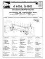 1
1
-
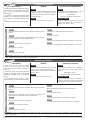 2
2
-
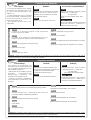 3
3
-
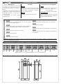 4
4
-
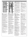 5
5
-
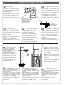 6
6
-
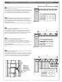 7
7
-
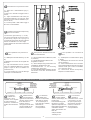 8
8
-
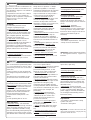 9
9
-
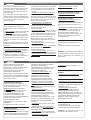 10
10
-
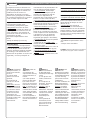 11
11
-
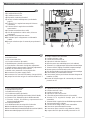 12
12
-
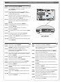 13
13
-
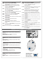 14
14
-
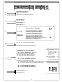 15
15
-
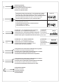 16
16
-
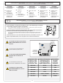 17
17
-
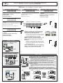 18
18
-
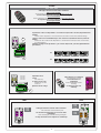 19
19
-
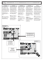 20
20
-
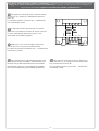 21
21
-
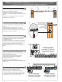 22
22
-
 23
23
-
 24
24


CAME G4000 Manuel utilisateur
- Taper
- Manuel utilisateur
- Ce manuel convient également à
dans d''autres langues
- italiano: CAME G4000 Manuale utente
- English: CAME G4000 User manual
- español: CAME G4000 Manual de usuario
- Deutsch: CAME G4000 Benutzerhandbuch
Documents connexes
-
CAME ZL37F Le manuel du propriétaire
-
-
CAME Z24-Z230 Spare Parts Manual
-
-
-
-
CAME ZBX4 Le manuel du propriétaire
-
-
-
CAME RSE Manuel utilisateur