Best WCN1306SS Guide d'installation
- Catégorie
- Hottes
- Taper
- Guide d'installation

99046206 rev. 03
INTENDED FOR DOMESTIC COOKING ONLY
INSTALLER: LEAVE THIS MANUAL WITH HOMEOWNER.
HOMEOWNER: USE AND CARE INFORMATION ON PAGE 10.
READ AND SAVE THESE INSTRUCTIONS
! !
INSTALLATION INSTRUCTIONS
BEST; Hartford, Wisconsin www.BestRangeHoods.com 800 558-1711
BEST; Drummondville, QC, Canada www.BestRangeHoods.ca 866 737-7770
To register your product online or for additional information visit www.BestRangeHoods.com
WCN1 SERIES

2
TO REDUCE THE RISK OF FIRE, ELECTRIC SHOCK OR
INJURY TO PERSONS, OBSERVE THE FOLLOWING:
1. Use this unit only in the manner intended by the manufacturer.
If you have questions, contact the manufacturer at the address
or telephone number listed in the warranty.
2. Before servicing or cleaning unit, switch power off at service
panel and lock service disconnecting means to prevent
power from being switched on accidentally. When the service
disconnecting means cannot be locked, securely fasten a
prominent warning device, such as a tag, to the service panel.
3. Installation work and electrical wiring must be done by
qualified personnel in accordance with all applicable codes
and standards, including fire-rated construction codes and
standards.
4. Sufficient air is needed for proper combustion and exhausting
of gases through the flue (chimney) of fuel burning equipment
to prevent backdrafting. Follow the heating equipment
manufacturer’s guidelines and safety standards such as
those published by the National Fire Protection Association
(NFPA) and the American Society for Heating, Refrigeration
and Air Conditioning Engineers (ASHRAE) and the local code
authorities.
5. When cutting or drilling into wall or ceiling, do not damage
electrical wiring and other hidden utilities.
6. Ducted fans must always be vented to the outdoors.
7. Do not use this unit with any solid-state speed control device.
8. To reduce the risk of fire, use only metal ductwork.
9. This unit must be grounded.
10. When applicable local regulations comprise more
restrictive installation and/or certification requirements,
the aforementioned requirements prevail on those of this
document and the installer agrees to conform to these at his
own expense.
TO REDUCE THE RISK OF A RANGE TOP GREASE FIRE:
a) Never leave surface units unattended at high settings. Boilovers
cause smoking and greasy spillovers that may ignite. Heat oils
slowly on low or medium settings.
b) Always turn the hood ON when cooking at high heat or
when flambeing food (i.e.: Crêpes Suzette, Cherries Jubilee,
Peppercorn Beef Flambé).
c) Clean ventilating fans frequently. Grease should not be allowed
to accumulate on fan, filters or in exhaust ducts.
d) Use proper pan size. Always use cookware appropriate for the
size of the surface element.
1. For indoor use only.
2. For general ventilating use only. Do not use to exhaust
hazardous or explosive materials and vapors.
3. To avoid motor bearing damage and noisy and/or unbalanced
impeller, keep drywall spray, construction dust, etc. off power
unit.
4. Your hood motor has a thermal overload which will
automatically shut off the motor if it becomes overheated. The
motor will restart when it cools down. If the motor continues to
shut off and restart, have the hood serviced.
5. The minimum hood distance above cooktop must not be less
than 24". For best capture of cooking impurities, the bottom of
the hood should be at a maximum of 30" above the cooking
surface.
6. Two installers are recommended because of the large size and
weight of this unit.
7. To reduce the risk of fire and to properly exhaust air, be sure to
duct air outside — Do not exhaust air into spaces within walls
or ceiling or into attics, crawl space or garage.
8. Because of the high exhausting capacity of this unit, you
should make sure enough air is entering the house to replace
exhausted air by opening a window close to or in the kitchen.
9. To reduce the risk of fire and electrical shock, the Best WCN1
Series models should only be installed with their own built-in
blower.
10. When used in recirculation mode, to reduce the risk of fire and
shock, use only conversion kit model ANKWCN1.
11. Please read specification label on product for further
information and requirements.
WARNING
!
CAUTION
TO REDUCE THE RISK OF INJURY TO PERSONS IN THE
EVENT OF A RANGE TOP GREASE FIRE, OBSERVE
THE FOLLOWING*:
1. SMOTHER FLAMES with a close-fitting lid, cookie sheet or
metal tray, then turn off the burner. BE CAREFUL TO PREVENT
BURNS. IF THE FLAMES DO NOT GO OUT IMMEDIATELY,
EVACUATE AND CALL THE FIRE DEPARTMENT.
2. NEVER PICK UP A FLAMING PAN — You may be burned.
3. DO NOT USE WATER, including wet dishcloths or towels —
This could cause a violent steam explosion.
4. Use an extinguisher ONLY if:
A. You own a Class ABC extinguisher and you know how to
operate it.
B. The fire is small and contained in the area where it started.
C. The fire department has been called.
D. You can fight the fire with your back to an exit.
* Based on “Kitchen Fire Safety Tips” published by NFPA.
WARNING
!

3
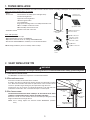
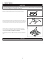
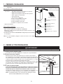
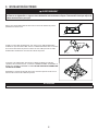
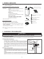
NOTE: Before proceeding to the installation, check the contents of the box. If items are missing or damaged, contact the manufacturer.
Make sure that the following items are included:
- Hood
- Accessories • Decorative flue assembly (lower and upper flues)
• Hood mounting bracket
• Upper flue mounting bracket
• Aluminum grease filters
• 8" round damper
• Bag of parts including: 9 #8 x 1-1/2" Phillips flat head screws,
2 M4 x 12 Phillips round head screws,
4 M4 x 8 Phillips round head screws,
2 washers and 3 wire connectors
- Installation manual
Parts sold separately:
- Duct, elbows, wall or roof caps
- Optional baffle filters kit (set of 2) AFBWCN1
- Optional flue extension for 10'-11' ceilings model AEWCN1SS
- Non-duct kit model ANKWCN1, mandatory for non-ducted installation
NOTE: During installation, protect countertop and/or cooktop.
1. PREPARE INSTALLATION
2. SELECT INSTALLATION TYPE
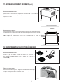
2.1 NON-DUCTED INSTALLATION
The ANKWCN1 non-duct kit is required for a non-ducted installation.
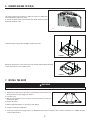
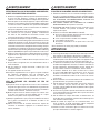
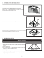
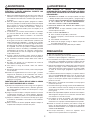
2.2 DUCTED INSTALLATION
Plan where and how the ductwork will be installed.
A straight, short duct run will allow the hood to perform most efficiently. Long duct
runs, elbows and transitions will reduce the performance of the hood. Use as few
of them as possible. Larger ducting may be required for longer duct runs.
Install wall or roof cap. Connect 8” round metal ductwork to cap and work back
towards the hood location. Use 2” metal foil duct tape to seal the joints.
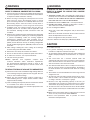
2.3 ALL INSTALLATIONS
The minimum hood distance above cooktop is 24”. A maximum of 30” above
cooktop is recommended for best capture of cooking impurities.
Distances over 30” are at the installer and users discretion providing that ceiling
height and decorative flue length allow it.
NOTE: 10'-11' ceilings require flue extension model AEWCN1SS (stainless
steel).
8” ROUND
DUCT
ROOF CAP
8” ROUND
ELBOW
WALL
CAP
HOOD
DECORATIVE
FLUE
HH0304A
24” MINIMUM ABOVE
COOKING
SURFACE
WARNING
!
When performing installation, servicing or cleaning the unit, it is recommended to wear safety glasses and gloves.
HR0266A
(1) DECORATIVE FLUE
ASSEMBLY
(1) UPPER FLUE
MOUNTING BRACKET
(2) GREASE FILTERS
(9) #8 X 1-1/2’’ PHILLIPS
FLAT HEAD SCREWS
(2) M4 X 12 PHILLIPS
ROUND HEAD SCREWS
(2) WASHERS
(3) WIRE CONNECTORS
(1) HOOD
MOUNTING BRACKET
(4) M4 X 8 PHILLIPS
ROUND HEAD SCREWS
(1) DAMPER

4
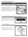
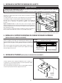
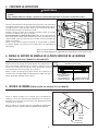
3. INSTALL HOOD MOUNTING BRACKET
HD1267A
FRAMING BEHIND DRYWALL
WALL STUDS
36
1
/8” = BOTTOM OF HOOD 24” ABOVE COOKTOP
42
1
/8” = BOTTOM OF HOOD 30” ABOVE COOKTOP
WARNING
!
• When cutting or drilling into wall, do not damage electrical wiring and other hidden utilities.
• When building framework, always follow all applicable construction codes and standards.
Construct wood wall framing that is even with the surface of wall studs.
Wood wall framing must be at least 1/2” thick and 3” high. Fasten wood wall
framing to wall studs for a solid installation.
Make sure that the height of the framing will allow the mounting bracket to be
secured to the framing within the dimensions shown (see illustration at right).
After wall surface is finished, using a level, draw a vertical line up to the
ceiling starting from the center of the planned hood location. Carefully center
and level the hood mounting bracket over installation location. Secure it to wall
framing using 3 #8 x 1-1/2" Phillips flat head screws.
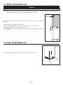
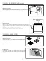
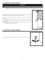
4. INSTALL UPPER FLUE MOUNTING BRACKET (DUCTED INSTALLATION ONLY)
Center the upper flue mounting bracket with the center line previously
drawn in step 3 and place it flush with the ceiling. Use the upper flue
mounting bracket as a template to mark the position of its screws.
Secure the upper flue mounting bracket to the wall using 2 #8 x 1-1/2"
Phillips flat head screws. Make sure that the bracket is tight against the
wall.
5. INSTALL PLENUM (NON-DUCTED INSTALLATION ONLY)
Center the plenum with the center line previously drawn in step 3 and
place it flush with the ceiling. Use the plenum mounting slots as a
template to mark the position of its screws.
Secure the plenum to the wall using 2 #8 x 1-1/2" Phillips flat head
screws. Make sure that the plenum is tight against the wall.
C
L
HD1150
CENTER OF INSTALLATION
UPPER FLUE MOUNTING
BRACKET SLOTS
MOUNTING BRACKET
FLUSH WITH CEILING
CEILING
L
C
HD1275
CEILING
PLENUM
FLUSH WITH
CEILING
CENTER OF
INSTALLATION
PLENUM
MOUNTING
SLOTS

5
7. INSTALL THE HOOD
1. Align the hood and center it above the hood mounting bracket. Gently lower
the hood until it securely engages the bracket.
2. Level the hood.
3. With the hood hanging in place, mark the four hole locations on wall (see
illustration at right).
4. Remove the hood.
5. Drill through marked holes on wall using a 3/32" drill bit.
6. Hang the hood to the wall bracket.
7. Secure the hood to the wall using 2 #8 x 1-1/2" Phillips flat head screws for top holes. Use 2 washers and 2 #8 x 1-1/2" Phillips flat head
screws for bottom holes.
WARNING
!
BE CAREFUL when installing the decorative flue and hood, they may have sharp edges.
HOLE LOCATIONS
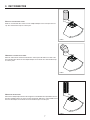
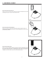
6. REMOVE GREASE FILTER(S)
Lay the back side of the hood flat on a table. Use a piece of cardboard to
avoid damaging the table or the hood.
To remove the grease filters, push the filter latch down and tilt each filter
downward. Set filters aside.
B
C
HD1269
Detach the junction box cover from the top of the hood by removing both retaining
screws. Set aside the cover and the screws.
HO0384
Install the damper using 4 M4 x 8 Phillips round head screws.
HO0389

6
WARNING
!
Risk of electric shock. Electrical wiring must be done by qualified personnel in accordance with all applicable
codes and standards. Before connecting wires, switch power off at service panel and lock service disconnecting
means to prevent power to be switched on accidentally.
8. CONNECT WIRING
Remove a knockout from the junction box cover top previously set aside.
HR0226
Install a UL approved strain relief (not included) on the house power cable at 4"
from the cable end. Run the power cable in the junction box cover opening, then
use the strain relief to secure the house power cable to the junction box cover.
Connect power cable to range hood wiring using included wire connectors.
Connect BLACK to BLACK, WHITE to WHITE and GREEN or BARE WIRE to
GREEN. DO NOT FORGET TO CONNECT THE GROUND.
Reinstall the junction box cover. Make sure all wires are inside the junction box
cover.
HD1157
STRAIN RELIEF
CAUTION
Make sure not to pinch any wire when reinstalling the junction box cover.

7
9. DUCT CONNECTION
VERTICALLY DUCTED INSTALLATION:
Slide a 8” round metal duct section over the adapter/damper on the hood up to the roof
cap. Use metal foil duct tape to seal the joint.
HJ0232
HORIZONTALLY DUCTED INSTALLATION:
Measure and install 8” round metal ductwork to wall cap and 90° elbow over duct collar
then install the 90° elbow over the adapter/damper on the hood. Use metal foil duct tape
to seal the joints.
HJ0233
NON-DUCTED INSTALLATION:
Remove the damper flaps. Measure the length of 8” round flexible duct (included in the non-
duct kit) required from the top of the hood to the plenum. Slide the 8” round flexible metal
duct over the adapter on the hood. Use metal foil duct tape to seal the joint.
HJ0234

8
10. PREPARE THE DECORATIVE FLUE
LOUVERS
HO0387
Peel off both corners at the top of the upper flue.
NOTE: For non-ducted installation only, remove enough plastic film to clear the louvers.
Gently slide upper flue inside lower flue, louvers end up.
NOTE: Upper flue can be reversed to hide louvers in some applications depending on installation
heights.
NOTE: Both lower and upper flues are included with the hood, but for ceilings of 9 ft. or more, discard the provided lower and upper flues
and use the optional flue extension, part no. AEWCN1SS (sold separately).
Remove the upper flue from inside the lower flue. Remove protective plastic film covering the lower
flue only.
11. INSTALL THE DECORATIVE FLUE
Carefully slide in place decorative flue base in the groove on the top of the hood.
HO0291
CAUTION
DO NOT REMOVE the protective plastic film covering the upper flue yet.

9
DUCTED INSTALLATION:
Slide up the upper flue until it is aligned with its mounting bracket. The bracket must be
inside the flue. Secure the upper flue to its bracket using 2 M4 x 12 Phillips round head
screws.
NOTE: Duct not shown in illustration to ease understanding.
Remove protective plastic film covering the upper flue and the hood.
HO0292
UPPER FLUE MOUNTING BRACKET
FRONT VIEW
UPPER
FLUE
HO0293
NON-DUCTED INSTALLATION:
Slide up the upper flue until it is aligned with the plenum. Secure the upper flue to the
plenum using 2 M4 x 12 Phillips round head screws.
Remove protective plastic film covering the upper flue and the hood.
11. INSTALL THE DECORATIVE FLUE (CONTINUED)
12. REINSTALL GREASE FILTERS
ALL INSTALLATIONS:
To reinstall the grease filters, align rear filter tabs with slots in the hood.
Push each filter into position. Make sure filters are securely engaged after
installation.
HD1270
NON-DUCTED INSTALLATION:
Install a charcoal filter on each aluminum grease filter back (A). Hold the
charcoal filter in place by inserting both ends of the 3 metal strips in each
aluminum grease filter frame (B).
HA0147
AB

10
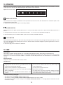
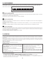
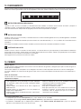
13. OPERATION
Always turn your hood on before you begin cooking to establish an air flow in the kitchen. Let the blower run for a few minutes to clear the
air after you turn off the range. This will help keep the whole kitchen cleaner and fresher.
Operate the hood as follows:
BLOWER BUTTON
When activated, the icon lights up and the blower turns on at the last saved speed. If there was no speed saved, the blower will be set at
speed 1.
To change the blower speed, press on the desired speed button 1, 2, 3 or 4. The current speed button will light up.
To turn off the blower, press on the blower button or press on the current speed button activated.
LIGHT BUTTON
When activated, the icon lights up as well as the dot(s) at the right of the icon that represent(s) the light intensity. By pressing once on the
icon, the first dot will light on. By pressing twice on the icon, the first and the second dots will light on. By pressing three times on the icon,
all three dots will light on.
To turn off the light, press a fourth time on the button.
14. CARE
Grease Filters
Grease filters should be cleaned frequently. Use a warm dishwashing detergent solution. Grease filters are dishwasher safe.
Clean all-metal filters in the dishwasher using a non-phosphate detergent. Discoloration of the filters may occur if using phosphate
detergents, or as a result of local water conditions - but this will not affect filter performance. This discoloration is not covered by the
warranty.
Non-ducted Filters
Change the non-duct recirculation filters every 6 months.
Hood Cleaning
Avoid when choosing a detergent:
- Any cleaners that contain bleach will attack stainless steel.
- Any products containing: chloride, fluoride, iodide, bromide will deteriorate surfaces rapidly.
- Any combustible products used for cleaning such as acetone, alcohol, ether, benzol, etc., are highly explosive and should never be
used close to a range.
Do:
• Regularly wash with clean cloth or rag soaked with warm water
and mild soap or liquid dish detergent.
• Always clean in the direction of original polish lines.
• Always rinse well with clear water (2 or 3 times) after cleaning.
Wipe dry completely.
• You may also use a specialized household stainless steel
cleaner.
Don’t:
• Use any steel or stainless steel wool or any other scrapers to
remove stubborn dirt.
• Use any harsh or abrasive cleansers.
• Allow dirt to accumulate.
• Let plaster dust or any other construction residues reach the
hood. During construction/renovation, cover the hood to make
sure no dust sticks to stainless steel surface.
DELAY OFF BUTTON
When activated, the icon lights up and blower current speed remains active for 10 min, then the blower turns off. Blower speed can be
changed within the 10 min delay.
To deactivate the delay off function, press on the delay off button.

11
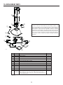
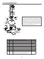
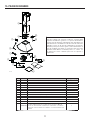
15. REPLACEMENT PARTS
HL0479
D
C
B
E
F
G
H
I
J
K
L
M
N
KEY NO.PART NO.DESCRIPTION 30" and 36"
1 S97021513 DECORATIVE UPPER AND LOWER FLUES WITH BRACKET 1
2 S99528418 DAMPER ASSEMBLY 1
3 S97021516 ELECTRONIC BOARD 1
4 S97021514 USER INTERFACE 1
5 S97021515 USER INTERFACE MOUNTING BRACKET 1
6 S99271697 C
APACITOR AND MAIN HARNESS ASSEMBLY 1
7 S99271698 LED MODULES (SET OF 2) 1
8 S99528414 A
LUMINUM GREASE FILTER (SOLD BY PIECE)2
9 S99010512 N
ON-DUCT RECIRCULATION FILTERS (SET OF 2) (METAL STRIPS NOT INCLUDED)1
10 S99010513 METAL STRIPS FOR NON-DUCT RECIRCULATION FILTER S99010512 (SET OF 3) 2
11 S99528407 MOTOR AND BLOWER ASSEMBLY 1
12 S99271696 POWER CABLE 1
13 S99840026 JUNCTION BOX 1
* S97021512
PARTS BAG INCLUDING: 9 #8 X 1-1/2" PHILLIPS FLAT HEAD SCREWS,
2 M4 X 12 PHILLIPS ROUND HEAD SCREWS, 4 M4 X 8 PHILLIPS ROUND HEAD
SCREWS, 2 WASHERS, 3 WIRE CONNECTORS, 1 UPPER FLUE MOUNTING BRACKET AND
1 HOOD MOUNTING BRACKET
1
* NOT SHOWN.
REPLACEMENT PARTS AND REPAIRS
In order to ensure your unit remains in good working condition, you
must use Broan-NuTone genuine replacement parts only. Broan-NuTone
genuine replacement parts are specially designed for each unit and are
manufactured to comply with all the applicable certification standards
and maintain a high standard of safety. Any third party replacement part
used may cause serious damage and drastically reduce the performance
level of your unit, which will result in premature failing. Broan-NuTone
recommends to contact a certified service depot for all replacement parts
and repairs.

12
16. WARRANTY
FIVE-YEAR LIMITED WARRANTY FOR BEST
®
PRODUCTS
Warranty Period and Exclusions: Broan-NuTone, LLC (the “Company”) warrants to the consumer purchaser of its product (“you”) that the product (the
“Product”) will be free from material defects in the materials or its workmanship for a period of five (5) years from the date of original purchase (or such
longer period as may be required by applicable law) or a period of two (2) years from the date of service for any labor provided on the Product.
The limited warranty period for any replacement parts provided by the Company and for any Products repaired or replaced under this limited warranty shall
be the remainder of the original warranty period (or such longer period as may be required by applicable law).
THIS WARRANTY DOES NOT EXTEND TO FLUORESCENT LAMP STARTERS, TUBES AND BULBS, FUSES, FILTERS, DUCTS, ROOF CAPS, WALL CAPS
AND OTHER ACCESSORIES FOR DUCTING. This warranty does not cover (a) normal maintenance and service, (b) normal wear and tear, (c) any Products or
parts which have been subject to misuse, abuse, abnormal usage, negligence, accident, improper or insufficient maintenance, storage or repair (other than
repair by the Company), (d) damage caused by faulty installation, or installation or use contrary to recommendations or instructions, (f) damage caused by
exposure to salt air, (g) damage in transit, (h) natural wear of finish, (i) Products in commercial or nonresidential use, (j) damage caused by fire, flood or
other act of God, or (k) Products with altered, defaced or removed serial numbers. This warranty covers only Products sold to consumers in North America.
This warranty supersedes all prior warranties and, subject to applicable law, is not transferable from the original consumer purchaser.
No Other Warranties: This Limited Warranty contains the Company’s sole obligation and your sole remedy for defective Products. The foregoing warranties
are exclusive and in lieu of any other warranties and conditions, express or implied. TO THE MAXIMUM EXTENT PERMITTED BY APPLICABLE LAW, THE
COMPANY DISCLAIMS AND EXCLUDES ALL OTHER EXPRESS WARRANTIES AND CONDITIONS, AND DISCLAIMS AND EXCLUDES ALL WARRANTIES
AND CONDITIONS IMPLIED BY LAW, INCLUDING WITHOUT LIMITATION THOSE OF MERCHANTABILITY AND FITNESS FOR A PARTICULAR PURPOSE.
To the extent that applicable law prohibits the exclusion of implied warranties or conditions, the duration of any applicable implied warranty or condition
is limited to the period specified for the express warranty above. Some jurisdictions (which may include the Province of Quebec or specific US states) do
not allow limitations on how long an implied warranty lasts, so the above limitation may not apply to you. Any oral or written description of the Product is
for the sole purpose of identifying it and shall not be construed as an express warranty.
Whenever possible, each provision of this Limited Warranty shall be interpreted in such manner as to be effective and valid under applicable law, but if any
provision is held to be prohibited or invalid, such provision shall be ineffective only to the extent of such prohibition or invalidity, without invalidating the
remainder of such provision or the other remaining provisions of the Limited Warranty.
Remedy: During the applicable limited warranty period, the Company will, at its option, provide replacement parts for, or repair or replace, without charge,
any Product or part thereof, to the extent the Company finds it to be covered by and in breach of this limited warranty under normal use and service. The
Company will ship the repaired or replaced Product or replacement parts to you at no charge. You are responsible for all costs for removal, reinstallation
and shipping, insurance or other freight charges incurred in the shipment of the Product or part to the Company. If you must send the Product or part
to the Company, as instructed by the Company, you must properly pack the Product or part—the Company is not responsible for damage in transit. The
Company reserves the right to utilize reconditioned, refurbished, repaired or remanufactured Products or parts in the warranty repair or replacement
process. Such Products and parts will be comparable in function and performance to an original Product or part and warranted for the remainder of the
original warranty period (or such longer period as may be required by applicable law).
Company reserves the right, in its sole discretion, to refund the money actually paid by you for the Product. If the Product or component is no longer
available, replacement may be made with a similar product of equal or greater value, at Company’s sole discretion. This is your sole and exclusive remedy
for breach of this limited warranty.
Exclusion of Damages: THE COMPANY’S OBLIGATION TO PROVIDE REPLACEMENT PARTS, OR REPAIR OR REPLACE, AT THE COMPANY’S OPTION,
SHALL BE YOUR SOLE AND EXCLUSIVE REMEDY UNDER THIS LIMITED WARRANTY AND THE COMPANY’S SOLE AND EXCLUSIVE OBLIGATION. THE
COMPANY SHALL NOT BE LIABLE FOR INCIDENTAL, INDIRECT, CONSEQUENTIAL OR SPECIAL DAMAGES ARISING OUT OF OR IN CONNECTION WITH
THE PRODUCT, ITS USE OR PERFORMANCE.
Some jurisdictions do not allow the exclusion or limitation of incidental or consequential damages, so the above limitation or exclusion may not apply
to you. This warranty gives you specific legal rights, and you may also have other rights, which vary from jurisdiction to jurisdiction. The disclaimers,
exclusions, and limitations of liability under this warranty will not apply to the extent prohibited by applicable law.
This warranty covers only replacement or repair of defective Products or parts thereof at the Company’s main facility and does not include the cost of field
service travel and living expenses.
Any assistance the Company provides to or procures for you outside the terms, limitations or exclusions of this limited warranty will not constitute a waiver
of such terms, limitations or exclusions, nor will such assistance extend or revive the warranty. The Company will not reimburse you for any expenses
incurred by you in repairing or replacing any defective Product, except for those incurred with the Company’s prior written permission.
How to Obtain Warranty Service: To qualify for warranty service, you must (a) notify the Company at the address or telephone number stated below within
seven (7) days of discovering the covered defect, (b) give the model number and part identification and (c) describe the nature of any defect in the Product
or part. At the time of requesting warranty service, you must present evidence of the original purchase date. If you cannot provide a copy of the original
written limited warranty, then the terms of the Company’s most current written limited warranty for your particular product will control.
PRODUCT SPECIFICATIONS
All illustrations and specifications in this catalog are based on the latest product information available at time of production. Broan-NuTone, LLC and
BEST® reserves the right to make changes at any time, without notice, in prices, colors, materials, equipment, specifications and models, place of
manufacture and to discontinue models or equipment.
Best
Broan-NuTone, LLC- 926 W. State Street, Hartford, WI 53207 1-800-637-1453
Best®, 550 Lemire Blvd., Drummondville, QC, Canada (1-866-737-7770) www.bestrangehoods.com

1
99046206 rév. 03
CONÇUE UNIQUEMENT POUR LA CUISSON DOMESTIQUE
INSTALLATEUR: LAISSER CE GUIDE AU PROPRIÉTAIRE.
PROPRIÉTAIRE: DIRECTIVES D'UTILISATION ET D'ENTRETIEN EN PAGE 10.
LIRE ET CONSERVER CES DIRECTIVES
! !
GUIDE D'INSTALLATION
BEST; Hartford, Wisconsin www.BestRangeHoods.com 800 558-1711
BEST; Drummondville, QC, Canada www.BestRangeHoods.ca 866 737-7770
Pour enregistrer votre produit en ligne ou pour obtenir plus d'information, consultez notre site www.BestRangeHoods.com
SÉRIE WCN1

2
AFIN DE RÉDUIRE LES RISQUES D’INCENDIE,
D’ÉLECTROCUTION OU DE BLESSURES CORPORELLES,
SUIVEZ LES DIRECTIVES SUIVANTES :
1. N’utilisez cet appareil que de la façon prévue par le manufacturier.
Si vous avez des questions, contactez le manufacturier à
l’adresse ou au numéro de téléphone indiqués dans la garantie.
2. Avant de réparer ou de nettoyer l’appareil, couper l’alimentation
électrique en verrouillant le panneau de distribution afin d’éviter
sa remise en marche accidentelle. Si le panneau de distribution
ne peut être verrouillé, y fixer un avertissement en évidence,
telle qu’une étiquette de couleur vive.
3. Les travaux d’installation et de raccordement électrique doivent
être effectués par une personne qualifiée, conformément
aux codes et aux standards de construction, incluant ceux
concernant la protection contre les incendies.
4. Une quantité d’air adéquate est requise afin d’assurer une bonne
combustion et l’évacuation des gaz par la cheminée dans le cas des
équipements alimentés au gaz afin de prévenir les retours de
cheminée. Conformez-vous aux instructions et aux standards de
sécurité des manufacturiers d’équipement de chauffage, tel qu’ils
sont publiés par la National Fire Protection Association (NFPA)
et l’American Society for Heating, Refrigeration and Air Conditioning
Engineers (ASHRAE) ainsi que les responsables des codes locaux.
5. Veillez à ne pas endommager le câblage électrique ou d’autres
équipements non apparents lors de la découpe ou du perçage
du mur ou du plafond.
6. Les ventilateurs avec conduits doivent toujours évacuer l’air à
l’extérieur.
7. Ne pas utiliser cet appareil avec une commande de vitesse à
semi-conducteur.
8. Afin de réduire les risques d’incendie, n’utilisez que des
conduits de métal.
9. Cet appareil doit être mis à la terre.
10. Lorsqu’une réglementation est en vigueur et qu’elle comporte
des exigences d’installation et/ou de certification plus
restrictives, lesdites exigences prévalent sur celles de ce
document et l’installateur entend s’y conformer à ses frais.
AFIN DE RÉDUIRE LES RISQUES DE FEU DE
CUISINIÈRE :
a) Ne jamais laisser les appareils de cuisson sans surveillance
lorsqu’ils sont réglés à feu vif. Les débordements engendrent de
la fumée et des déversements graisseux pouvant s’enflammer.
Chauffez l’huile lentement, à feu doux ou moyen.
b) Mettez toujours la hotte en marche lorsque vous cuisinez à feu
vif ou que vous cuisinez des mets flambés (par ex. : crêpes
Suzette, cerises jubilé, steaks au poivre flambés).
c) Nettoyez régulièrement la (les) roue(s) du ventilateur. Ne laissez
pas la graisse s’accumuler sur le ventilateur, les filtres ou les
conduits d’évacuation.
d) Utilisez le bon format de casserole. Servez-vous toujours de
casseroles et d’ustensiles appropriés à la dimension de la
surface chauffante.
1. Pour une utilisation à l’intérieur seulement.
2. Pour usage domestique seulement. Ne pas utiliser pour évacuer
des vapeurs ou des matières dangereuses ou explosives.
3. Afin d’éviter tout dommage au moteur et de débalancer ou de
rendre bruyante la roue du moteur, garder votre appareil à l’abri
des poussières de gypse et de construction/rénovation, etc.
4. Le moteur de votre hotte possède une protection thermique qui
éteindra automatiquement le moteur s’il devient surchauffé. Le
moteur redémarrera automatiquement une fois refroidi. Si le
moteur continue à arrêter et à redémarrer, faites-le vérifier.
5. La distance minimale de la hotte au-dessus de la surface
de cuisson NE DOIT PAS être inférieure à 24 po. Pour une
meilleure évacuation des odeurs de cuisson, la distance
maximale recommandée au-dessus de la surface de cuisson
est de 30 po.
6. Deux installateurs sont recommandés lors de l’installation vu la
grande dimension et le poids de cet appareil.
7. Afin de réduire les risques d’incendie, assurez-vous d’évacuer
l’air à l’extérieur. Ne pas évacuer l’air dans des espaces
restreints comme l’intérieur des murs ou plafond ou dans le grenier,
faux plafond ou garage.
8. En raison de la grande capacité d’évacuation de cette hotte, il
est recommandé d’ouvrir une fenêtre dans ou près de la cuisine
afin de remplacer l’air évacué.
9. Afin de réduire les risques d’incendie et d’électrocution, les
hottes Best de la série WCN1 ne doivent être installées qu'avec
leur ventilateur intérieur intégré.
10. Afin de réduire les risques de feu ou d'électrocution, si la
hotte est utilisée en mode recirculation, utiliser uniquement
l'ensemble de recirculation modèle ANKWCN1.
11. Veuillez consulter l’autocollant apposé à l’intérieur de la hotte
pour plus d’information ou d'autres exigences.
AVERTISSEMENT
!
ATTENTION
AFIN D’ÉVITER TOUT RISQUE DE BLESSURES LORS
D’UN FEU DE CUISINIÈRE, SUIVEZ CES DIRECTIVES* :
1. Étouffez les flammes avec un couvercle hermétique, une tôle à
biscuits ou un plateau métallique et ensuite, éteindre le brûleur.
PRENEZ SOIN D’ÉVITER LES BRÛLURES. SI LES FLAMMES
NE S’ÉTEIGNENT PAS IMMÉDIATEMENT, ÉVACUEZ LES
LIEUX ET APPELEZ LES POMPIERS.
2. NE PRENEZ JAMAIS UNE CASSEROLE EN FLAMMES
DANS VOS MAINS. Vous pourriez vous brûler.
3. N’UTILISEZ PAS D’EAU, incluant un linge à vaisselle ou une
serviette mouillée, cela pourrait occasionner une violente
explosion de vapeur.
4. N’utilisez un extincteur QUE DANS LE CAS OÙ :
A. Vous savez qu’il s’agit d’un extincteur de classe ABC et que
vous en connaissez le fonctionnement.
B. Le feu est petit et limité à l’endroit où il a débuté.
C. Les pompiers ont été avisés.
D. Vous pouvez combattre le feu en ayant accès à une sortie
de secours.
*Tirées du Kitchen Fire Safety Tips publié par la NFPA.
AVERTISSEMENT
!

3
1. PRÉPARER L'INSTALLATION
NOTE : Avant de commencer l’installation, vérifier le contenu de la boîte. Si des pièces sont manquantes ou endommagées, contacter
le détaillant.
S’assurer que les articles suivants sont inclus :
- Hotte
- Accessoires • Ensemble conduit décoratif (inférieur et supérieur)
• Support de montage de la hotte
• Support de montage du conduit décoratif supérieur
• Filtres à graisses en aluminium
• Volet rond de 8 po
• Sac de pièces comprenant:
9 vis #8 x 1-1/2 po Phillips à tête plate;
2 vis M4 x 12 Phillips à tête ronde
4 vis M4 x 8 Phillips à tête ronde
2 rondelles et 3 capuchons de connexion
- Manuel d'installation
Pièces vendues séparément :
- Conduits, coudes, capuchons de mur ou de toit
- Filtres à chicane optionnels (ensemble de 2) AFBWCN1
- Rallonge de conduit décoratif optionnelle pour plafonds de 10 pi à 11 pi
modèle AEWCN1SS
- Ensemble de recirculation modèle ANKWCN1, obligatoire pour une installation
en recirculation
NOTE : Lors de l'installation, protéger la surface de cuisson ou le comptoir
de cuisine.
2. CHOISIR LE TYPE D'INSTALLATION
2.1 INSTALLATION EN RECIRCULATION
L'ensemble de recirculation ANKWCN1 est requis pour ce type d'installation.
2.2 INSTALLATION AVEC CONDUITS
Déterminer à quel endroit et de quelle façon les conduits seront installés.
Un conduit droit et court permettra à la hotte de fonctionner plus efficacement.
Un conduit long avec des coudes et des transitions réduira la performance de
la hotte. En utiliser le moins possible. Pour une grande distance, un conduit
d’évacuation d’air au diamètre plus grand peut être requis.
Installer un capuchon de toit ou de mur. Relier le conduit de 8 po rond en métal
au capuchon, puis acheminer le conduit jusqu’à l’emplacement de la hotte.
Sceller les joints avec du ruban adhésif de métal de 2 po de largeur.
2.3 TOUTES LES INSTALLATIONS
La distance minimale entre le bas de la hotte et la surface de cuisson est
de 24 po. Un maximum de 30 po au-dessus de la surface de cuisson est
recommandé pour une meilleure évacuation des odeurs de cuisson.
Les distances au-delà de 30 po sont à la discrétion de l’installateur et de
l’utilisateur, si la hauteur du plafond et du conduit décoratif le permettent.
NOTE: Les plafonds de 10 pi à 11 pi nécessitent une rallonge de conduit
décoratif modèle AEWCN1SS (acier inoxydable).
CONDUIT ROND
DE
8 PO
CAPUCHON DE TOIT
COUDE ROND
DE
8 PO
CAPUCHON
MURAL
HOTTE
CONDUIT
DÉCORATIF
HH0304F
24 PO MINIMUM AU-DESSUS
DE
LA SURFACE DE CUISSON
AVERTISSEMENT
!
Lors de l’installation, de l’entretien ou du nettoyage de l’appareil, il est recommandé de porter des lunettes et des gants de sécurité.
HR0266F
(1) ENSEMBLE DE
CONDUIT DÉCORATIF
(1) SUPPORT DE MONTAGE DU
CONDUIT DÉCORATIF SUPÉRIEUR
(2) FILTRES À GRAISSES
(9) VIS #8 X 1-1/2 PO PHILLIPS
À TÊTE PLATE
(2) VIS M4 X 12 PHILLIPS
À TÊTE RONDE
(2) RONDELLES
(3) CAPUCHONS DE CONNEXION
(1) SUPPORT DE MONTAGE
DE LA HOTTE
(4) VIS M4 X 8 PHILLIPS
À TÊTE RONDE
(1) VOLET

4
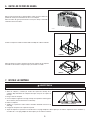
3. INSTALLER LE SUPPORT DE MONTAGE DE LA HOTTE
HD1267F
CADRE DERRIÈRE LE MUR
MONTANTS
AVERTISSEMENT
!
• Veillez à ne pas endommager le câblage électrique ou d’autres équipements non apparents lors de la découpe
ou du perçage du mur ou du plafond.
• Lors de la construction de la charpente, toujours suivre les codes et standards de construction en vigueur.
Construire un cadre mural en bois encastré entre les montants et au même
niveau que ceux-ci.
Le cadre mural doit avoir au moins 1/2 po d’épaisseur et 3 po de hauteur. Pour
une installation solide, s’assurer de fixer le cadre mural aux montants.
S’assurer que la hauteur du cadre permettra au support de montage d’y
être bien fixé en respectant les dimensions indiquées (voir l’illustration
ci-contre).
Après la finition du mur, à l’aide d’un niveau, tracer une ligne verticale
jusqu’au plafond à partir du centre de l’emplacement de la hotte. Mesurer et
marquer l’emplacement des vis de retenue à l’aide des mesures apparaissant
dans l’illustration à droite.
Centrer et niveler le support de montage à l'endroit où la hotte sera installée. Le
fixer au cadre mural à l'aide de 3 vis #8 x 1-1/2 po Phillips à tête plate.
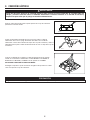
4. INSTALLER LE SUPPORT DE MONTAGE DU CONDUIT DÉCORATIF SUPÉRIEUR
(INSTALLATION AVEC CONDUITS SEULEMENT)
Centrer le support de montage du conduit décoratif supérieur selon la
ligne précédemment tracée à l’étape 3 et le positionner au ras du plafond.
Utiliser les fentes du support comme gabarit pour marquer la position des
vis.
Fixer au mur le support de montage du conduit supérieur à l’aide de 2 vis
#8 x 1-1/2 po Phillips à tête plate. S’assurer que le support de montage
soit bien appuyé contre le mur.
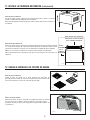
5. INSTALLER LE PLENUM (INSTALLATION EN RECIRCULATION SEULEMENT)
Centrer le plenum selon la ligne précédemment tracée à l’étape 3 et
le positionner au ras du plafond. Utiliser les fentes du plenum comme
gabarit pour marquer la position des vis.
Fixer au mur le plenum à l’aide de 2 vis #8 x 1-1/2 po Phillips à tête plate.
S’assurer que le plenum soit bien appuyé contre le mur.
C
L
HD1150
CENTRE DE L'INSTALLATION
FENTES DU SUPPORT DE
MONTAGE DU CONDUIT
DÉCORATIF SUPÉRIEUR
SUPPORT DE MONTAGE
AU RAS DU PLAFOND
PLAFOND
L
C
HD1275
PLAFOND
PLENUM
AU RAS DU
PLAFOND
CENTRE DE
L
'INSTALLATION
FENTES DU
PLENUM
36
1
/8 PO = BAS DE LA HOTTE 24 PO AU-DESSUS DU PLAN DE CUISSON
42
1
/8 PO = BAS DE LA HOTTE 30 PO AU-DESSUS DU PLAN DE CUISSON

5
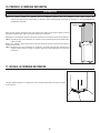
7. INSTALLER LA HOTTE
1. Aligner la hotte et la centrer au-dessus du support de montage de la hotte.
Abaisser doucement la hotte jusqu’à ce qu’elle s’accroche au support de
montage.
2. Mettre la hotte de niveau.
3. Avec la hotte accrochée au support de montage, marquer la position des
quatre trous au mur (voir l'illustration ci-contre).
4. Retirer la hotte.
5. Percer les quatre trous dans le mur à l'aide d'une mèche de 3/32 po.
6. Suspendre la hotte au support de montage.
7. Fixer la hotte au mur à l'aide de 2 vis #8 x 1-1/2 po Phillips à tête plate pour les trous du haut. Utiliser 2 rondelles et 2 vis #8 x 1-1/2 po
Phillips à tête plate pour les trous du bas.
AVERTISSEMENT
!
SOYEZ PRUDENT lors de l’installation du conduit décoratif et de la hotte, il pourrait y avoir des arêtes vives.
EMPLACEMENT DES TROUS
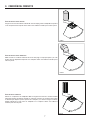
6. RETIRER LES FILTRES À GRAISSES
Poser le dos de la hotte à plat sur une table. Placer au préalable un
morceau de carton pour éviter d’endommager la table et la hotte.
Retirer les filtres à graisses en poussant sur le loquet et en faisant
basculer chaque filtre. Mettre les filtres de côté.
B
C
HD1269
Détacher le couvercle de la boîte de jonction du dessus de la hotte en enlevant les
deux vis de retenue. Mettre le couvercle et les vis de côté.
HO0384
Installer le volet à l'aide de 4 vis M4 x 8 Phillips à tête ronde.
HO0389

6
AVERTISSEMENT
!
Risque de choc électrique. Le raccordement électrique doit être effectué par du personnel qualifié en respectant
les normes et règlements en vigueur. Avant d’effectuer le branchement, coupez l’alimentation électrique depuis le
tableau de distribution principal.
8. INSTALLATION ÉLECTRIQUE
Enlever une alvéole défonçable du dessus du couvercle de la boîte de jonction
préalablement mis de côté.
HR0226
Installer un serre-câble homologué UL (non fourni) sur le câble d’alimentation
résidentiel à 4 po du bout du câble. Passer le câble d’alimentation dans l’ouverture
du couvercle de la boîte de jonction et utiliser le serre-câble pour fixer le câble
d’alimentation résidentiel au couvercle de la boîte de jonction.
Connecter le fil d’alimentation de la hotte au câblage résidentiel à l’aide des
capuchons de connexion fournis: Connecter le fil NOIR au NOIR, le fil BLANC au
BLANC et le fil VERT ou DÉNUDÉ au VERT. NE PAS OUBLIER DE CONNECTER
LA MISE À LA TERRE.
Réinstaller le couvercle de la boîte de jonction. S’assurer que tous les fils sont à
l’intérieur du couvercle de la boîte de jonction.
HD1157
SERRE-CÂBLE
ATTENTION
S’assurer de ne coincer aucun fil lors de la réinstallation du couvercle de la boîte de jonction.

7
9. RACCORDER LE CONDUIT
INSTALLATION EN ÉVACUATION VERTICALE :
Glisser une section de conduit rond en métal de 8 po par-dessus l’adaptateur/volet. Sceller
hermétiquement le joint à l’aide de ruban adhésif de métal.
HJ0232
INSTALLATION EN ÉVACUATION HORIZONTALE :
Mesurer et installer un conduit rond en métal de 8 po jusqu'au capuchon mural et un
coude de 90° sur l'adaptateur/volet de la hotte. Sceller hermétiquement les joints à l’aide
de ruban adhésif de métal.
HJ0233
INSTALLATION EN RECIRCULATION :
Enlever les volets de l’adaptateur. Mesurer la longueur requise de conduit flexible rond de
8 po en métal (inclus dans le kit de recirculation) pour couvrir la distance entre le dessus
de la hotte et le plenum. Glisser le conduit flexible rond de 8 po en métal par-dessus
l’adaptateur de la hotte. Sceller le joint avec du ruban adhésif de métal.
HJ0234

8
10. PRÉPARER LE CONDUIT DÉCORATIF
FENTES
HO0387
Enlever juste assez de plastique protecteur pour dégager les coins supérieurs du conduit décoratif
supérieur.
NOTE : Uniquement pour une installation sans conduit, enlever assez de plastique pour dégager
les fentes.
Glisser délicatement le conduit décoratif supérieur dans le conduit décoratif inférieur, le côté des
fentes vers le haut.
NOTE : Le conduit décoratif supérieur peut être inversé pour cacher les fentes dans certaines
applications selon les hauteurs d’installation.
NOTE : Les conduits décoratifs inférieur et supérieur sont inclus avec la hotte. Toutefois, pour les plafonds de9pieds ou plus, se défaire
des conduits décoratifs inférieur et supérieur et utiliser le conduit décoratif optionnel, pièce n° AEWCN1SS (vendu séparément).
Retirer le conduit décoratif supérieur de l'intérieur du conduit décoratif inférieur. Retirer la pellicule
de plastique protectrice recouvrant le conduit décoratif inférieur seulement.
11. INSTALLER LE CONDUIT DÉCORATIF
Glisser délicatement en place le conduit décoratif dans la rainure sur le dessus de la hotte.
HO0291
ATTENTION
NE PAS RETIRER pour l’instant le film protecteur de plastique recouvrant le conduit décoratif supérieur.
La page charge ...
La page charge ...
La page charge ...
La page charge ...
La page charge ...
La page charge ...
La page charge ...
La page charge ...
La page charge ...
La page charge ...
La page charge ...
La page charge ...
La page charge ...
La page charge ...
La page charge ...
La page charge ...
-
 1
1
-
 2
2
-
 3
3
-
 4
4
-
 5
5
-
 6
6
-
 7
7
-
 8
8
-
 9
9
-
 10
10
-
 11
11
-
 12
12
-
 13
13
-
 14
14
-
 15
15
-
 16
16
-
 17
17
-
 18
18
-
 19
19
-
 20
20
-
 21
21
-
 22
22
-
 23
23
-
 24
24
-
 25
25
-
 26
26
-
 27
27
-
 28
28
-
 29
29
-
 30
30
-
 31
31
-
 32
32
-
 33
33
-
 34
34
-
 35
35
-
 36
36


Best WCN1306SS Guide d'installation
- Catégorie
- Hottes
- Taper
- Guide d'installation
dans d''autres langues
- English: Best WCN1306SS Installation guide
- español: Best WCN1306SS Guía de instalación
Documents connexes
Autres documents
-
Broan-NuTone EW4830SS Le manuel du propriétaire
-
Broan EW4330SS Le manuel du propriétaire
-
Broan EW4636SS Le manuel du propriétaire
-
-
NuTone NW830SS Manuel utilisateur
-
-
-