
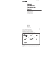
Parts for Installation and Connection
Pièces de montage et de raccordement
Onderdelen voor installatie en aansluiting
The numbers in the list are keyed to those in the instructions.
Les numéros de la liste correspondent à ceux des instructions.
De nummers in de afbeelding verwijzen naar die in de montage-aanwijzingen.
3-856-406-11 (1)
Installation/Connections
Installation/Connexions
Montage/Aansluitingen
Sony Corporation 1996
1
× 1
2
× 1
3
× 1
456
7
× 1
The release key 4 is used for dismounting the unit. See the operating instructions manual for details.
La clé de déverrouillage 4 est nécessaire pour démonter l’appareil. Consulter le mode d’emploi pour
plus de détails.
De ontgrendelsleutel 4 dient om het apparaat te verwijderen. Zie de gebruiksaanwijzing voor meer
details.
× 1 × 1
× 1
XR-C110
XR-C111
FM/AM
FM/MW/LW
Cassette Car
Stereo

Installation
Precautions
•Choose the installation location carefully so that the unit does not
hamper the driver during driving.
•Avoid installing the unit where it would be subject to high
temperatures, such as from direct sunlight or hot air from the heater,
or where it would be subject to dust, dirt or excessive vibration.
•Use only the supplied mounting hardware for a safe and secure
installation.
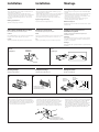
Mounting angle adjustment
Adjust the mounting angle to less than 20°.
Installation
Précautions
• Choisir soigneusement l’emplacement de l’installation, pour que
l’appareil ne gêne pas la conduite.
• Eviter d’installer l’appareil dans un endroit exposé à des températures
élevées, comme en plein soleil ou à proximité d’une bouche d’air
chaud, ou à de la poussière, saleté ou vibrations violentes.
• Pour garantir un montage sûr, n’utiliser que le matériel fourni.
Réglage de l’angle de montage
Ajuster l’inclinaison à un angle inférieur à 20°.
Montage
Voorzorgsmaatregelen
• Installeer het apparaat op een plaats waar het u niet hindert tijdens
het rijden.
• Installeer het apparaat niet op plaatsen waar het blootgesteld wordt
aan hoge temperaturen zoals van direct zonlicht of de warme
luchtstroom van de auto-verwarming, aan sterke trillingen, of waar
het in contact komt met veel stof of vuil.
• Gebruik voor het veilig en stevig monteren van het apparaat
uitsluitend de bijgeleverde montage-onderdelen.
Maximale montagehoek
Installeer het apparaat nooit onder een hoek van meer dan 20° met het
horizontale vlak.
Retrait et pose de la façade
Avant d’installer l’appareil, déposer la façade.
Retrait
Appuyer sur la touche RELEASE pour ouvrir la façade. Faites-la ensuite
glisser légèrement vers la gauche et enlevez-la en tirant vers vous.
Pose
Aligner les points A et B, puis pousser la façade jusqu’au déclic.
How to Detach and Attach the Front Panel
Before installing the unit, detach the front panel.
To detach
Press the RELEASE button to open up the front panel. Then slide the
front panel a little to the left, and pull it off towards you.
To attach
Align the parts A and B, and push the front panel until it clicks.
Verwijderen en bevestigen van het
afneembare voorpaneel
Verwijder, alvorens met het installeren te beginnen, het
afneembare voorpaneel.
Verwijderen
Druk op de RELEASE toets om het voorpaneel te openen. Schuif het
voorpaneel vervolgens een beetje naar links en verwijder het paneel
door het naar u toe te trekken.
Bevestigen
Breng de delen A en B op één lijn en druk het voorpaneel aan totdat
dit vastklikt.
To attach
Pose
Aanbrengen
To detach
Retrait
Verwijderen
B
A
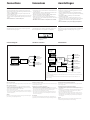
Mounting Example
Installation in the dashboard
Exemple de montage
Installation dans le tableau de bord
Montagevoorbeeld
Montage in het dashboard
123
Fire wall
Paroi ignifuge
Brandschot
2
Dashboard
Tableau de bord
Dashboard
3
Bend these claws, if necessary.
Si nécessaire, plier ces griffes.
Buig indien nodig deze lipjes om.
182 mm
53 mm
1
Note for Connecting
If there is alternator noise (a whining sound when raising engine
speed), earth the master unit by connecting it to a metal point of the
car with the supplied chassis earth cord 7. Connect the ground cord
to the master unit with part 2 as shown in the illustration. (In case
you do not use part 2, take screw 6 instead.)
Remarque sur le raccordement
Si l’alternateur génère des interférences (pleurage lorsque le
régime moteur augmente), reliez l’appareil principal à la masse en
le raccordant à un point métallique de la voiture au moyen du fil
de masse pour châssis 7 fourni. Raccordez le fil de masse à
l’appareil principal au moyen de la pièce 2 comme indiqué dans
l’illustration. (Si vous n’utilisez pas la pièce 2, utilisez la pièce 6.)
Opmerking over aansluiting
Wanneer de alternator storing veroorzaakt (een gierend geluid dat
samen met het motortoerental toeneemt), moet het hoofdtoestel
worden geaard door het met behulp van de meegeleverde
chassisaardingskabel 7 aan te sluiten op een metalen gedeelte van
de wagen. Sluit de aardingskabel op het hoofdtoestel aan met
behulp van onderdeel 2 zoals op de tekening aangegeven. (Indien
u onderdeel 2 niet gebruikt, gebruik dan schroef 6 in plaats
daarvan.)
RELEASE button
Touche RELEASE
RELEASE toets
to a metal point of the car
à un point métallique de la voiture
naar metalen gedeelte van de wagen
2
7

Connections
Caution
•This unit is designed for negative ground 12 V DC operation only.
•Before making connections, disconnect the ground terminal of the car
battery to avoid short circuits.
•Connect the yellow and red power input leads only after all other
leads have been connected.
•Be sure to connect the red power input lead to the positive 12 V power
terminal which is energized when the ignition key is in the accessory
position.
•Run all earth wires to a common earth point.
Précautions
• Cet appareil est conçu pour fonctionner sur courant continu de 12 V
avec masse négative.
• Avant d’effectuer les connexions, débrancher la borne de terre de la
batterie du véhicule pour éviter tout court-circuit.
• Brancher les fils d’entrée d’alimentation jaune et rouge seulement
après avoir terminé tous les autres branchements.
• Veiller à ne pas raccorder le fil rouge d’entrée d’alimentation à la
borne positive de 12 V qui est alimentée quand la clé de contact est sur
la position accessoires.
• Rassembler tous les fils de terre en un point de masse commun.
Let op!
•Dit apparaat is ontworpen voor gebruik op gelijkstroom van een 12
Volts auto-accu, negatief geaard.
•Alvorens te beginnen met het maken van aansluitingen, dient de
aardklem van de auto-accu te worden losgemaakt. Dit om kortsluiting
te voorkomen.
•Sluit de gele en rode stroomdraden pas aan nadat alle andere
aansluitingen zijn gemaakt.
•Zorg ervoor dat de rode stroomdraad op de positieve 12 V accu-
aansluiting wordt aangesloten. De draad komt dan onder spanning te
staan wanneer de contactsleutel wordt omgedraaid in de stand
“ACC”.
•Sluit alle aarddraden op een gemeenschappelijk aardpunt aan.
Connexions Aansluitingen
Terugsteltoets
Druk, nadat u het apparaat heeft geïnstalleerd en de aansluitingen heeft
gemaakt, met een balpen of een ander puntig voorwerp op de
terugsteltoets.
Bouton de réinitialisation
Quand l’installation et les connexions sont terminées, appuyer sur le
bouton de réinitialisation avec un stylo bille ou un objet pointu.
Reset Button
When the installation and connections are over, be sure to press the
reset button with a ball-point pen etc.
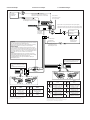
Connection Diagram
Example 1/Exemple 1/Voorbeeld 1 Example 2/Exemple 2/Voorbeeld 2
Schémas de connexion Aansluitschema
BUS AUDIO IN
BUS CONTROL IN
Note on the control leads
The power antenna control lead (blue) supplies 12V DC power when you turn on the unit.
Notes on speaker connections
• Use speakers with an impedance of 4 to 8 ohms, and with adequate power handling
capacities. Otherwise, the speakers may be damaged.
• Do not connect the terminals of the speaker system to the car chassis, and do not connect
the terminals of the right speaker with those of the left speaker.
• Do not connect the speakers in parallel.
• Do not connect any active speakers (with built-in amplifiers) to the speaker terminals of
the unit. Doing so may damage the active speakers. Therefore, be sure to connect passive
speakers to these terminals.
Warning
If you have a power antenna without a relay box, connecting this unit with the supplied
power connecting cord 5 may damage the antenna.
Remarque sur les fils de contrôle
Le fil de contrôle de l’antenne électrique (bleu) fourni du courant continu de 12V lorsque
vous mettez l’appareil sous tension.
Remarques sur la connexion des haut-parleurs
• Utiliser des haut-parleurs avec une impédance de 4 à 8 ohms et qui peuvent supporter
l’alimentation fournie sinon ils risqueraient d’être endommagés.
• Ne pas connecter les bornes du système de haut-parleur au châssis de la voiture et ne pas
raccorder les bornes du haut-parleur droit aux bornes du haut-parleur gauche.
• Ne pas essayer de connecter les haut-parleurs en parallèle.
• Ne pas connecter d’enceintes acoustiques actives (avec amplificateurs intégrés) aux
bornes d’enceinte de cet appareil, pour éviter d’endommager les enceintes. Veiller à
raccorder des enceintes passives.
Avertissement
Si vous disposez d‘une antenne électrique sans boîtier de relais, le branchement de cet
appareil au moyen du cordon d‘alimentation fourni 5 risque d‘endommager l‘antenne.
Opmerking betreffende de bedieningsaansluitingen
Het aansluitsnoer voor de elektrische antenne (blauw) levert +12V gelijkstroom als het
toestel wordt ingeschakeld.
Opmerkingen betreffende de luidsprekeraansluitingen
• Gebruik luidsprekers met een impedantie van 4 tot 8 Ohm en let op dat die het vermogen
van de versterker kunnen verwerken. Zo niet, dan kunnen de luidsprekers ernstig
beschadigd raken.
• Verbind in geen geval de aansluitingen van de luidsprekers met het chassis van de auto
en sluit de aansluitingen van de rechter en linker luidspreker niet op elkaar aan.
• Probeer niet de luidsprekers parallel aan te sluiten.
• Sluit geen actieve luidsprekers (luidsprekers met ingebouwde versterkers) aan op de
luidsprekeraansluitingen van het apparaat. Dit kan resulteren in beschadiging van de
actieve luidsprekers. Op deze aansluitingen mogen uitsluitend passieve luidsprekers
worden aangesloten.
Opgelet
Indien u een elektrische antenne heeft zonder relaiskast, kan het aansluiten van deze
eenheid met het bijgeleverde netsnoer 5 de antenne beschadigen.
LINE OUT
CD changer
Changeur de CD
CD-wisselaar
XR-C110
XR-C111
Front speakers
Haut-parleurs avant
Voorluidsprekers
Rear speakers
Haut-parleurs arrière
Achterluidsprekers
CD changer
Changeur de CD
CD-wisselaar
Source selector
Sélecteur de source
Geluidsbronkiezer
CD changer
Changeur de CD
CD-wisselaar
Power amplifier
Amplificateur de puissance
Eindversterker
XR-C110
XR-C111
BUS
CONTROL IN
BUS
AUDIO IN
Front speakers
Haut-parleurs avant
Voorluidsprekers
Rear speakers
Haut-parleurs arrière
Achterluidsprekers
Rear speakers
Haut-parleurs arrière
Achterluidsprekers
Reset button
Bouton de réinitialisation
Terugsteltoets
For connecting two changers, the source selector XA-C30 (optional) and the BUS cable RC-61 (1 m) or RC-62 (2 m) (optional)
are necessary.
Pour le raccordement de deux changeurs, vous devez utiliser le sélecteur de source XA-C30 (optionnel) et le câble BUS RC-61 (1 m)
ou RC-62 (2 m) (optionnels).
Als u twee CD-wisselaars wilt aansluiten, hebt u de bronkeuzeschakelaar XA-C30 (optioneel) en de BUS kabel RC-61 (1 m)
of RC-62 (2 m) nodig.

Connections Example Connexions de l’exemple voorbeeldaansluitingen
BUS CONTROL IN
RCA pin cord (RC-63 (1 m), RC-64 (2 m) or RC-65 (5 m)) (not supplied)
Cordon à broche RCA (RC-63 (1 m), RC-64 (2 m) ou RC-65 (5 m)) (non fournis)
Tulpstekkersnoer (RC-63 (1 m), RC-64 (2 m) of RC-65 (5 m)) (niet bijgeleverd)
Pin
Broche
Pin
7
8
Function
Fonction
Functie
continuous power supply
alimentation continue
continu voeding
power antenna control
antenne électrique
elektrische antenne
Function
Fonction
Functie
switched power supply
alimentation commutée
geschakelde voeding
ground
masse
aarding
Pin
Broche
Pin
4
5
Colour
Couleur
Kleur
Yellow
Jaune
Geel
Blue
Bleu
Blauw
Colour
Couleur
Kleur
Red
Rouge
Rood
Black
Noir
Zwart
Function
Fonction
Functie
+; Speaker, Front, Left
+; haut-parleur, avant, gauche
+: Luidspreker, voor, links
–; Speaker, Front, Left
–; haut-parleur, avant, gauche
–: Luidspreker, voor, links
+; Speaker, Rear, Left
+; haut-parleur, arrière, gauche
+: Luidspreker, achter, links
–; Speaker, Rear, Left
–; haut-parleur, arrière, gauche
–: Luidspreker, achter, links
Function
Fonction
Functie
+; Speaker, Rear, Right
+; haut-parleur, arrière, droit
+: Luidspreker, achter, rechts
–; Speaker, Rear, Right
–; haut-parleur, arrière, droit
–: Luidspreker, achter, rechts
+; Speaker, Front, Right
+; haut-parleur, avant, droit
+: Luidspreker, voor, rechts
–; Speaker, Front, Right
–; haut-parleur, avant, droit
-: Luidspreker, voor, rechts
Pin
Broche
Pin
5
6
7
8
Pin
Broche
Pin
1
2
3
4
Colour
Couleur
Kleur
Colour
Couleur
Kleur
Purple
Mauve
Paars
White
Blanc
Wit
Gray
Gris
Grijs
Green
Vert
Groen
Negative polarity positions 2, 4, 6 and 8 have striped cords.
Les positions de polarité négative 2, 4, 6 et 8 sont dotées de cordons rayés.
De negatieve posities 2, 4, 6 en 8 hebben gestreepte kabels.
Positions 1, 2, 3 and 6 do not have pins.
Les positions 1, 2, 3 et 6 ne comportent pas de broche.
De posities 1, 2, 3 en 6 hebben geen pins.
7135
8246
1357
2468
1357
2468
7135
8246
Power amplifier
Amplificateur de puissance
Eindversterker
BUS AUDIO IN
LINE OUT
BUS CONTROL IN
Rear speakers
Haut-parleurs arrière
Achterluidsprekers
AMP REM
Blue/white striped
Rayé bleu/blanc
Blauw/wit gestreept
Max. supply current 0.3 A
Courant max. fourni 0,3 A
Max. voedingsstroom 0,3 A
Fuse (10 A)
Fusible (10 A)
Zekering (10 A)
from car antenna
de l’antenne de la voiture
van een auto-antenne
BUS cable (supplied to CD changer)
Câble BUS (fourni avec le changeur CD)
BUS kabel (bijgeleverd met de CD-wisselaar)
RCA pin cord (supplied to CD changer)
Cordon à broche RCA (fourni avec le changeur CD)
Tulpstekkersnoer (bijgeleverd met de CD-wisselaar)
CD changer
Changeur de CD
CD-wisselaar
to a car’s auxiliary power connector
vers un connecteur d’alimentation auxiliaire de
la voiture
naar de hulpvoedingsaansluiting van de auto
to a car’s speaker connector
vers un connecteur de haut-parleur de la voiture
naar een luidsprekeraansluiting van de auto
5
WARNING
Auxiliary power connectors may vary depending on the car. Be sure to check the
power connection diagram sheet supplied with the unit.
Improper connections may damage your car. If the supplied power connecting
cord can not be used with your car, consult your nearest Sony dealer.
AVERTISSEMENT
Le connecteur d’alimentation auxiliaire peut varier suivant le type de voiture.
Vérifiez le schéma du connecteur d’alimentation auxiliaire de votre voiture pour
vous assurer que les connexions correspondent. Un raccordement incorrect peut
occasionner des dommages à votre voiture. Si le cordon d’alimentation fourni ne
peut être utilisé avec votre voiture, consultez votre revendeur Sony.
OPGELET
De hulpvoedingsaansluitingen kunnen per auto verschillen. Controleer het
voedingsaansluitschema dat bij dit toestel wordt geleverd. Onjuiste aansluiting
kan uw wagen schade toebrengen. Indien de meegeleverde
stroomaansluitingskabel voor uw wagen niet bruikbaar is, raadpleeg uw
dichtstbijzijnde Sony-dealer.
-
 1
1
-
 2
2
-
 3
3
-
 4
4


Sony XR-C110 Guide d'installation
- Taper
- Guide d'installation
- Ce manuel convient également à
dans d''autres langues
- English: Sony XR-C110 Installation guide
- Nederlands: Sony XR-C110 Installatie gids