
1
Owners Installation, Operation, and Safety Manual
FR1200G / FR2400G / FR4200G / FR4400G
SD1200G / Series DC Transfer Pumps
FR600G Series AC Transfer Pumps
Tuthill Transfer Systems 8825 Aviation Drive Ft. Wayne, IN 46809 (260) 747-7529 www.tuthill.com

2
®
Table of Contents
Safety Information .............................................................................................................. 3
Installation .......................................................................................................................... 3
DC Electrical Wiring ............................................................................................................ 6
DC Wiring Diagram ............................................................................................................. 9
AC Electrical Wiring .......................................................................................................... 10
AC Wiring Diagram ........................................................................................................... 11
Operating Instructions ....................................................................................................... 12
Padlocking ........................................................................................................................ 12
Troubleshooting ................................................................................................................ 13
Dimensional Information ................................................................................................... 14
DC Technical Information (1200 / 2400 Series)................................................................. 15
DC Technical Information (4200 / 4400 Series)................................................................. 16
AC Technical Information ................................................................................................. 17
Kits and Parts ................................................................................................................... 18
Accessories ...................................................................................................................... 19
Safety Approvals and Certifications .................................................................................. 20
Motor Tag Information .............................. …………………………………………………..…20
Thank You!
Thank you for your purchase! Your Fill-Rite product comes with over 80 years of pump
manufacturing experience behind it, providing you the value that comes with superior
performance, user friendly design, long service life, and solid, simple engineering.
Experience that gives you peace of mind.
Pump Your Heart Into It
About This Manual
From initial concept and design through its final production, your Fill-Rite pump is built to
give you years of trouble free use. To ensure it provides that service, it is critical that
you read this entire manual prior to attempting to install or operate your new pump.
Become familiar with the terms and diagrams, and pay close attention to the highlighted
areas with the following labels:
WARNING! Emphasizes an area in which personal injury or even death could
result from failure to follow instructions properly. Mechanical damage may also
occur.
IMPORTANT! These boxes contain information that illustrates a point that
may save time or may be key to proper operation, or clarifies a step.
CAUTION! Failure to observe a “Caution” can cause damage to the
equipment.
At Tuthill, your satisfaction with our products is paramount to us. If you have questions or
need assistance with your product, please contact us at 1-800-634-2695 (M-F 8 AM–5
PM ET).

3
Safety Information
WARNING! Electrical wiring should be performed ONLY by a licensed
electrician in compliance with local, state, and national electrical code NEC/ANSI/
NFPA 70, NFPA 30, and NFPA 30A, as appropriate to the intended use of the
pump. Threaded rigid conduit, sealed fittings, and conductor seal should be used
where applicable. The pump must be properly grounded. Improper installation or
use of this pump can result in serious bodily injury, or death!
WARNING! To ensure safe and proper operation of your equipment, it is critical
to read and adhere to all of the following safety warnings and precautions.
Improper installation or use of this product can cause serious bodily injury or
death!
NEVER smoke near the pump, or use the pump near open flames when
pumping a flammable liquid! Fire can result!
A filter should be used on the pump outlet to ensure no foreign material is
transferred to the fuel tank. We recommend Fill-Rite filters for best results.
Threaded pipe joints and connections must be sealed with the appropriate
sealant or sealant tape to minimize the possibility of leaks.
Storage tanks must be securely anchored to prevent shifting or tipping when
full or empty.
To minimize static electricity build up, use only static wire conductive hose
when pumping flammable fluids, and keep the fill nozzle in contact with the
container being filled during the filling process.
The pump motor is equipped with thermal overload protection; if
overheated, the motor will shut off to prevent damage to the windings. If this
happens:
2400, 4400, 600, and SD600 series pumps will reset automatically
when the pump cools down.
1200 & 4200 series pumps must be reset manually to operate again.
Wait until the motor cools down and turn the power switch off to reset.
WARNING! This product shall not be used to transfer fluids into any type of
aircraft.
WARNING! This product is not suited for use with fluids intended for human
consumption or fluids containing water.
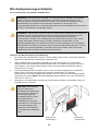
Installation
Your Fill-Rite pump is designed to be mounted on a skid tank using the threaded inlet
flange supplied with the pump (see attached diagrams). Your pump features an integral
bypass valve to recirculate the fluid when the pump is operating with the nozzle closed.
WARNING! In Skid Tank applications, be sure the tank is properly secured so it
cannot shift or move whether the tank is empty or full.
CAUTION! Do not use additional check valves or foot valves unless they have a
proper pressure relief valve built into them. Note that additional check valves will
reduce rate of flow.

4
CAUTION! A pressure retaining fill cap can be used to reduce fuel loss through
evaporation, but note that it will reduce the flow rate.
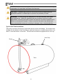
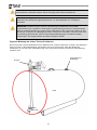
Typical Skid Tank Installation
CAUTION! Threaded pipe joints and connections must be sealed with the
appropriate sealant or sealant tape to prevent the possibility of leaks.
WARNING! Fill-Rite pumps are designed for use with stationary and mobile
tank applications. While DC powered units are excellent choice for mobile
applications, anchoring the tank to which the pump is mounted is paramount to
ensure no movement in transit. Failure to secure the tank to the vehicle can
cause uncontrolled movement, resulting in damage, injury, and potential fire.
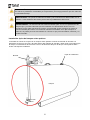
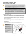
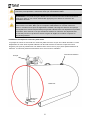
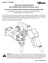
The pump mounts to the bung of a skid tank by way of the inlet flange. The suction tube
threads into the bottom of the inlet flange, and must extend to a length that positions it at
least 3” from the bottom of the tank. The skid tank should be equipped with a vent cap.
Pump
Tank
Vent Cap
3” Min

5
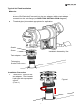
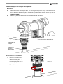
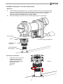
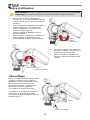
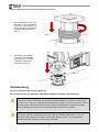
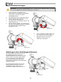
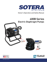
1. Thread the 1” pipe into the
tank adapter. Seal threads
liquid tight with appropriate
sealant.
(Figure 1)
Materials:
1” telescoping suction pipe extended to a length that will extend to within 3” of the
bottom of the tank when screwed into the tank adapter with the tank adapter
screwed into the tank flange (see SKID TANK INSTALLATION diagram).
Threaded pipe joint sealant appropriate for application.
Typical Skid Tank Installation
Figure 1
Installation Assembly View
Installation Procedure:
Gasket
Screen
Tank Adapter
Telescoping
Suction Pipe

6
2. Screw the inlet flange (with
suction pipe) into the tank
bung; seal threads liquid tight
with appropriate thread
sealant (Figure 2).
Typical Skid Tank Installation (cont’d)
Figure 2
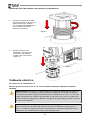
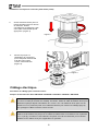
3. Mount the pump on the
adapter; making sure
the seal and screen are
installed as shown.
(Figure 3).
Figure 3
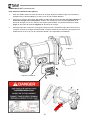
CAUTION! DC powered pumps are designed to operate on either 12 or 24 VDC
(depending on model). Where applicable, use the supplied battery cable to
supply power to the pump from a 12 or 24 VDC battery. A 30 amp fuse (20 amp
fuse on 24 VDC motors) should be installed on the battery cable (see wiring
diagram page 9) to protect the wire in case of electrical short.
CAUTION! Voltage drop in wiring varies depending on the distance from the
battery to the pump and the gauge of the wire used. If the distance is greater
than 20’, refer to national, international, or local electrical codes to ensure the
wire is of the correct size for this application.
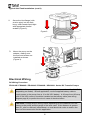
Electrical Wiring
DC Wiring Procedure
FR1200G / FR2400G / FR4200G / FR4400G / SD1202G Series DC Transfer Pumps

7
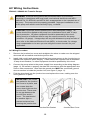
1. Remove pump’s electrical junction box cover and straighten the 2 wires to make
the stripped wire ends accessible outside of the junction box.
2. Screw furnished cable connector into NPT* conduit opening in pump junction box.
3. Strip 6 inches of the outer covering from one end of the furnished electrical cable
being careful not to damage the black and red wire insulation.
4. Loosen cable connector nut and pass the stripped end of the furnished cable
through the cable connector. Tighten the cable connector nut.
5. Strip ½ inch of the insulation from the ends of the red and black cable wires. Using
the furnished wire nuts, connect these wires to the pump wires matching the
colors. Be sure no bare wire is exposed.
6. Fold wires into junction box and replace cover making sure the gasket is in place.
Make sure all screws are seated so there is no space between the cover and the
junction box (see “IMPORTANT!” information box and diagram page 10).
Wiring To A Vehicle Electrical System (see wiring diagram, page 9)
1. Pass the electrical wires to the source of the vehicle power system, supporting the
wires as necessary and protecting them from sharp edges, heat, and anything that
could damage the wires.
2. To determine if the vehicle electrical system is negative (-) or positive (+) ground,
check the battery marking of the terminal that is wired to the vehicle frame or
motor block. The red wire from the pump will connect to positive battery post and
the black wire from the pump will connect to negative battery post.
3. Attach one end of the fuse holder to the end of the ungrounded wire. Make a solid
electrical connection with the other end of the fuse holder to the ungrounded side
of the battery, as close to the battery as possible. Make a solid electrical
connection to the grounded side of the battery with the remaining wire. The battery
terminal or the end of the battery cable is recommended.
4. Check all connections to make sure they are connected per instructions and all
electrical codes. Install the 30 amp fuse (20 amp fuse in 24 VDC installations) in
the fuse holder. The installation is now complete.
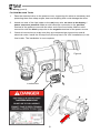
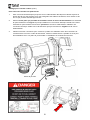
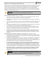
Instructions Before Proceeding With DC Wiring
The pump needs to be electrically bonded to supply tank or vehicle frame. To electrically
bond pump, remove green bonding screw located next to junction box cover. Insert this
screw through eyelet of furnished green bonding wire assembly and refasten it securely
to the pump. The other end of the wire is to be stripped of insulation and the bare wire
securely bonded to the vehicle / trailer frame or skid tank.
WARNING! Do not connect the positive or negative power to the green screw or
wire as this could cause a fire.
Wiring Instructions (see Figure 4, Page 8)
WARNING! Do not attempt to power the pump from vehicle wiring smaller than
12 gage such as the cigarette lighter wire because these thin wires could
overheat and cause a fire.
*M20 Conduit entry on GE models

8
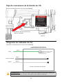
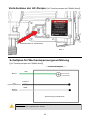
DC Wiring (cont’d)
Figure 4
Junction Box
For Skid Mounted Tanks
1. Pass the electrical wires to the power source, supporting the wires as necessary and
protecting them from sharp edges, heat and anything that could damage the wires.
2. Attach one end of the fuse holder to the red pump wire, as close to the battery /
power source as possible. Make a solid electrical connection to the positive
terminal of the power source with the other end of the fuse holder. Make a solid
connection with the black pump wire to the negative terminal of the power source.
3. Check all connections to make sure they are connected per instructions and all
electrical codes. Install the 30 amp fuse (20 amp fuse in 24 VDC installations) in the
fuse holder. The installation is now complete.
Wire in

9
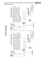
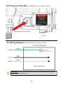
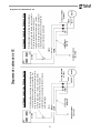
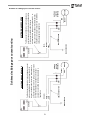
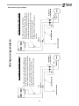
DC Wiring Diagram
Fuse to be located outside of hazardous area, as
close to the power source as possible. If the
wiring from the power source to the pump is
greater than 20’, refer to the applicable Electrical
Code (National, International, or local) to ensure
the wire is of the correct size for the application.
Fuse to be located outside of hazardous area,
as close to the power source as possible. If
the wiring from the power source to the pump
is greater than 20’, refer to the applicable
Electrical Code (National, International, or
local) to ensure the wire is of the correct size
for the application.
DC Wiring Diagram

10
WARNING! Electrical wiring should be performed ONLY by a licensed
electrician in compliance with local, state, and national electrical code NEC/
ANSI/NFPA 70, NFPA30, and NFPA 30A, as appropriate to the intended use of
the pump. The pump must be properly grounded. Improper installation or use
of this pump can result in serious bodily injury, or death!
CAUTION! All pumps should operate at the rated nameplate voltage. AC
power should be supplied to the pump from a dedicated circuit with 15 amp
circuit protection. No other equipment should be powered by this circuit.
Wiring must be of sufficient size to carry the correct current for the pump
(minimum 12 gauge). Voltage drop will vary with distance to pump and size of
wire; refer to the National Electrical Code (NEC), or local codes, for voltage
drop compensation to be sure you are using the correct size wire for your
application.
AC Wiring Instructions
AC Wiring Procedure
1. Remove the junction box cover and straighten the wires to make sure the stripped
wire ends are accessible outside the junction box.
2. Install rigid conduit and appropriate wiring from power source to the junction box to
maintain the explosion proof integrity. Power should be supplied from a dedicated
15 amp circuit breaker; no other equipment should be powered by this circuit.
3. Connect the pump wires to the power supply lines according to the wiring diagram
(page 11). Be certain to properly insulate the connections with the appropriate wire
nuts or other connectors. Note that the ground wire MUST be connected (ground
wire connection is inside the junction box; see figure 5, page 11).
4. Fold the wires back into the junction box and replace the cover, making sure the
cover gasket is in place.
IMPORTANT! Be certain
the gasket for the junction
box cover is in place, and
the screws draw the
cover down tight over the
junction box. There must
be no gap between the
junction box and it’s
cover. The seal should
be weather tight to
prevent moisture from
entering the junction box.
FR600G / SD602G AC Transfer Pumps
Junction Box Gasket
Junction Box Cover

11
Figure 5
AC Wiring Diagram (FR600G Series AC Transfer Pumps)
AC Pump Junction Box (FR600G Series AC Transfer Pumps)
Ground screw in junction box
WARNING! Ground wire in supply wiring MUST be connected to the ground
screw inside the junction box.

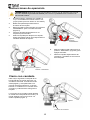
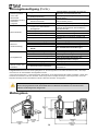
12
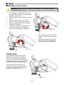
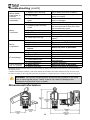
Operating Instructions
1. If so equipped, reset meter to “0” (do
not reset while in use as this will cause
damage to the meter).
2. Remove dispensing nozzle from nozzle
boot.
3. Move the switch lever to the “ON”
position to power the pump (figure 5).
4. Insert the dispensing nozzle into the
container to be filled.
5. Operate the nozzle to dispense fluid;
release nozzle when the desired
amount of fluid has been dispensed.
Figure 6
“OFF” position
WARNING! Always keep the nozzle in contact with the container being filled
during the filling process to minimize the possibility of static electricity build up.
6. Move switch lever to the “OFF”
position (Figure 6) to turn off the
pump.
7. Remove the dispensing nozzle
from the container being filled
and store it in the nozzle boot.
Figure 5
“ON” position
Padlocking
Your Fill-Rite pump nozzle can be
padlocked to the pump for added
security. With the pump turned off,
and the nozzle in the stored position,
a padlock can be inserted through the
locking link and the nozzle handle.
The locking link is located on the
nozzle side of the pump, and can be
pivoted into position to work with a
variety of nozzles (Figure 7).
Figure 7
Locking Link

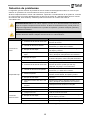
13
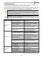
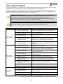
Troubleshooting
The following troubleshooting guide is provided to offer basic diagnostic assistance in the
event you encounter abnormal service from your Fill-Rite product.
If you have questions regarding installing, operating, or servicing your product, please feel
free to contact our Customer Service Department at 1-800-634-2695 (M-F 8 AM–5 PM
ET). You can also reach us on the World Wide Web at “www.fillrite.com”.
WARNING! DO NOT open or attempt to repair the motor on your Fill-Rite pump.
Return it to the place of purchase for service. Opening the motor case can
compromise the integrity of the Explosion Proof construction and will void any
existing warranty and certification.
WARNING! Be certain all power to the pump is disconnected prior to
performing any service or maintenance.
Symptom Cause Cure
Pump won't
prime.
1. Suction line problem.
Check for leaks or obstructions in
suction line.
2. Bypass valve open.
Remove and inspect valve; must
move freely & be free of debris.
3. Vanes sticking.
Check vanes and slots for nicks,
burrs and wear.*
4. Excessive rotor or vane
wear.
Inspect rotor & vanes for excessive
wear or damage; replace if
necessary.*
5. Vapor Lock.
Reduce vertical and horizontal
distance from pump to liquid;
remove automatic nozzle.
Low capacity.
1. Excessive dirt in screen. Remove and clean screen.
2. Suction line problem.
Check suction line for leaks or
restrictions; it may be too small,
too long or not airtight.
3. Bypass valve sticking.
Remove and inspect valve; must
move freely & be free of debris.
4. Outlet blocked.
Check pump outlet, hose, nozzle &
filter for blockage.
5. Vanes sticking.
Check vanes and slots for wear.*
6. Excessive rotor or vane
wear.
Inspect rotor & vanes for excessive
wear or damage; replace if
necessary.*
7. Hose or nozzle damage. Replace hose or nozzle.
8. Plugged filter. Replace filter.
9. Low fluid level. Fill tank.
Pump runs
slowly.
1. Incorrect voltage.
Check incoming line voltage while
pump is running.
2. Vanes sticking.
Inspect vanes and slots for nicks,
burrs and wear.*
3. Wiring problem. Check for loose connections.
4. Motor problem. Return to place of purchase.
See page 14 for explanation of Bold text and * items.

14
Troubleshooting (cont’d)
Motor stalls /
fuse blows or
thermal
protector trips
repeatedly.
1. Bypass valve sticking.
Remove and inspect valve; must
move freely & be free of debris.
2. Low voltage.
Check incoming line voltage while
pump is running.
3. Excessive rotor or vane
wear.
Check rotor & vanes for excessive
wear or damage.*
4. Debris in pump cavity. Clean debris from pump cavity.
Motor
overheats.
1. Pumping high viscosity
fluids.
These fluids can only be pumped
for short periods of time (less than
30 minutes duty cycle).
2. Clogged screen. Remove and clean screen.
3. Restricted suction pipe. Remove and clean pipe.
4. Motor failure. Return to place of purchase.
5. Pump rotor lock-up.
Clean and check pump rotor and
vanes.*
Motor
Inoperative.
1. No power Check incoming power.
2. Switch failure. Replace switch (KIT120SW).
3. Motor failure. Return to place of purchase.
4. Thermal protector
failure.
Return to place of purchase.
5. Incorrect/loose wiring. Check wiring.
Fluid leakage.
1. Bad o-ring gasket. Check all o-ring gaskets.
2. Dirty shaft seal. Clean seal & seal cavity.
3. Bad shaft seal. Replace seal.
4. Incompatible fluid.
Refer wetted parts list to fluid
manufacturer.
5. Loose fasteners. Tighten fasteners.
Pump hums but
will not operate.
1. Motor failure. Return to place of purchase.
2. Broken rotor key. Remove all debris & replace key.
Bold text indicates service that cannot be performed by the owner; pump must be returned to the point of purchase for
this type of service.
* Repairs marked with an asterisk (*) will require Repair Kit KIT120RG Kit includes replacement rotor and new vanes,
as well as a number of other important seals and components to complete the repair. Details of this kit are on page 18.
WARNING! Disconnect electrical power and relieve any pressure in the lines
prior to servicing this pump! Failure to do so can result in damage to the
equipment and personal injury or death!
Dimensional Information

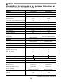
15
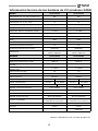
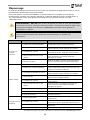
Motor
Power - AC 115, 230, 115/230 VAC N/A N/A
HZ 50, 60, 50/60 N/A N/A
Power - DC 12, 24, 12/24 12 24
HP (horsepower) rating 1/4 HP 1/4 HP
Power cord length (feet) 18' 18'
Power cord gauge (AWG) 12 AWG 12 AWG
DC Power cord connectors NONE NONE
Amps (FLA) 20 10
RPM 2600 2600
Duty cycle 30 min. 30 min.
Thermal protection switch Yes Yes
Circuit protection fuse NONE NONE
Certification
UL, cUL Motor, ATEX,
CE*, ANZEx, INMETRO
UL, cUL Motor, ATEX,
CE*, ANZEx, INMETRO
Pump
Type- rotary, diaphragm, gear,
vane
Rotary Vane Rotary Vane
GPM in supplied configuration Up to 15 Up to 15
GPM open flow - no hose or nozzle Up to 18.5 Up to 18.5
By-pass pressure rating (psi) - Max 16 psi 16 psi
Dry vac (in Hg) 5 5
Head- Max (Ft.) 37 37
Anti-siphon valve None None
Inlet - Size / Thread 1” NPT 1” BSPP* 1” NPT 1” BSPP*
Outlet – Size / Thread 3/4” NPT 3/4” BSPP* 3/4” NPT 3/4” BSPP*
Mount 2” Bung NPT 2” BSPT* 2” Bung NPT 2” BSPT*
Material -pump housing Cast Iron Cast Iron
Material- wetted material BUNA-N BUNA-N
Rotor material Powdered Iron Powdered Iron
Rotor vane material Sintered Bronze Sintered Bronze
Compatible fluids
Diesel, gasoline, BioDiesel
to B20, E15, Kerosene
Diesel, gasoline,
BioDiesel to B20, E15,
Kerosene
Strainer Mesh Size 20 x 20 20 x 20
Warranty 2 Years 2 Years
Certification
ATEX, CE*, ANZEx,
INMETRO
ATEX, CE*, ANZEx,
INMETRO
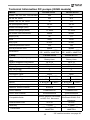
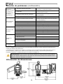
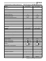
Technical Information DC pumps (G/GE models)
FR1200 Series
FR2400 Series
FR1200 Series
FR2400 Series
* CE certified models: see page 20

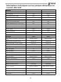
16
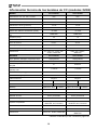
Motor
Power - AC 115, 230, 115/230 N/A N/A
HZ 50, 60, 50/60 N/A N/A
Power - DC 12, 24, 12/24 12 24
HP (horsepower) rating 1/4 HP 1/4 HP
Power cord length (feet) 18' 18'
Power cord gauge (AWG) 12 AWG 12 AWG
DC Power cord connectors NONE NONE
Amps (FLA) 20 10
RPM 2600 2600
Duty cycle 30 min. 30 min.
Thermal protection switch Yes Yes
Circuit protection fuse NONE NONE
Certification
UL, cUL Motor, ATEX,
CE*, ANZEx, INMETRO
ATEX, CE*, ANZEx,
INMETRO
Pump
Type- rotary, diaphragm, gear,
vane
Rotary Vane Rotary Vane
GPM in supplied configuration Up to 20 Up to 20
GPM open flow - no hose or nozzle 21 Up to 20
By-pass pressure rating (psi) - Max 16 psi 16 psi
Dry vac (in Hg) 5 5
Head- Max (Ft.) 37 37
Anti-siphon valve None None
Inlet - Size / Thread 1” NPT 1” BSPP* 1” NPT 1” BSPP*
Outlet – Size / Thread 1” NPT 1” BSPP* 1” NPT 1” BSPP*
Mount 2” Bung NPT 2” BSPT* 2” Bung NPT 2” BSPT*
Material -pump housing Cast Iron Cast Iron
Material- wetted material BUNA-N BUNA-N
Rotor material Powdered Iron Powdered Iron
Rotor vane material Sintered Bronze Sintered Bronze
Compatible fluids
Diesel, gasoline,
BioDiesel to B20, E15,
Kerosene
Diesel, gasoline, BioDiesel
to B20, E15, Kerosene
Strainer Mesh Size 20 x 20 20 x 20
Warranty 2 Years 2 Years
Certification
ATEX, CE*, ANZEx,
INMETRO
ATEX, CE*, ANZEx,
INMETRO
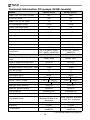
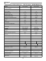
Technical Information DC pumps (G/GE models)
FR4200 Series FR4400 Series
FR4200 Series
FR4400 Series
* CE certified models: see page 20

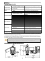
17
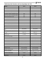
Motor
Power -AC 115, 230, 115/230 115 VAC 115 VAC
HZ 50, 60, 50/60 60 HZ 60 HZ
Power - DC 12, 24, 12/24 N/A N/A
HP (horsepower) rating 1/6 HP 1/6 HP
Power cord length (feet) N/A N/A
Power cord gauge (AWG) N/A N/A
DC Power cord N/A N/A
Amps (FLA) 2.0 A 2.0 A
RPM 2000 2000
Duty cycle 30 min. 30 min.
Thermal protection switch Yes Yes
Circuit protection fuse None None
Certification UL/cUL UL/cUL
Pump
Type- rotary, diaphragm, gear,
vane
Rotary Vane Rotary Vane
GPM in supplied configuration Up to 14.8 Up to 14.8
GPM open flow - no hose or
nozzle
Up to 17.4 Up to 17.4
By-pass pressure rating (psi) -
Max
16 psi 16 psi
Dry vac (in Hg) 5 5
Head- Max (Ft.) 37 37
Anti-siphon valve None None
Inlet - Size / Thread 1” NPT 1” NPT
Outlet – Size / Thread 1” NPT 1” NPT
Mount 2” Bung (NPT) 2” Bung (NPT)
Material -pump housing Cast Iron Cast Iron
Material- wetted material BUNA-N BUNA-N
Rotor material Powdered Iron Powdered Iron
Rotor vane material Sintered Bronze Sintered Bronze
Compatible fluids
Diesel, gasoline, BioDiesel
up to B20, E15, Kerosene
Diesel, gasoline, BioDiesel
up to B20, E15, Kerosene
Strainer Mesh Size 20 x 20 20 x 20
Warranty 2 Years 1 Years
Certification UL/cUL UL/cUL
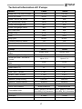
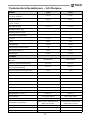
Technical Information AC Pumps
FR600
SD600
FR600
SD600

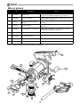
18
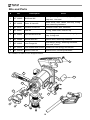
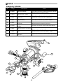
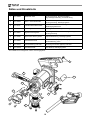
# Kit Description Parts
1 KIT120BD* BioDiesel Kit*
O-ring seal, bypass valve poppet, bypass
cap seal, inlet seal
2 KIT120RG Rotor & Vane Kit
Rotor cover, rotor, vanes, rotor key, O-ring
seal, attaching hardware
3 KIT120JC Junction Cover Kit Junction cover, seal, fasteners
4 KIT120SL Seal Kit O-ring, shaft seals, retainer clip
5 KIT120BV By-Pass Service Kit
Screen, bypass valve, valve spring, bypass
cap, O-ring seal
6 KIT120NB Nozzle Boot Kit Nozzle boot, attaching hardware
7 KIT120BG Inlet Flange Kit
Inlet flange (bung), attaching hardware,
inlet seal, screen
8 KIT120SG Inlet Gasket and Screen Gasket for inlet (bung) and screen
9 KIT120SW Switch Lever Kit Switch lever, mounting hardware
Kits and Parts
6
5
7
2
4
3
9
8
*KIT120BD not called out in diagram below.

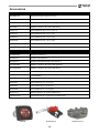
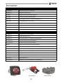
19
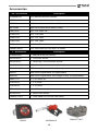
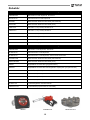
3/4” Accessories Description
FRHMN075S 3/4” Manual Aluminum Nozzle
N075DAU10 3/4” Automatic Nozzle
807CMK 800 Series Mechanical Meter (Gallons)
807CLMK 800 Series Mechanical Meter (Liters)
700F3135 3/4” x 12’ Hose, UL
FRH07512 3/4” x 12 Hose
FRH07514 3/4” x 14’ Hose
FRH07520 3/4” x 20’ Hose
S075H1314 3/4” Multi-Plane Swivel
1200KTG9075 3/4” Filter Head (for use with F18 filters)
1” Accessories Description
FRHMN100S 1” Manual Aluminum Nozzle
N100DAU10 1” Automatic Nozzle
N100DAU13 1” Ultra-High Flow Automatic Nozzle
901CMK4200 900 Series Mechanical Meter (Gallons)
901CLMK4200 900 Series Mechanical Meter (Liters)
900CD 900 Series Digital Meter (Programmable)
900CDP 900 Series Digital Meter with Integral Pulsar (Programmable)
300F7773 1” x 12’ Hose, UL
FRH10012 1” x 12 Hose
FRH10014 1” x 14’ Hose
FRH10020 1” x 20’ Hose
S100H1315 1” Multi-Plane Swivel
700ACCF7017 1” Filter Head (for use with F40 filters)
Accessories
900CD
N100DAU13
700ACCF7017

20
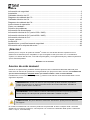
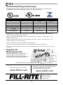
Safety Testing Approvals
The Fill-Rite line of pumps have been safety tested for compliance to the standards set
forth by Underwriters Laboratories, ATEX, ANZEx, INMETRO, and lEx.
DC000945-000 Rev 3
Visit us on the web at:
www.fillrite.com
Learn more about Tuthill Corporation and
our family of high quality, value minded
products at:
www.tuthill.com
8825 Aviation Drive
Ft. Wayne, IN 46809
1-800-634-2695
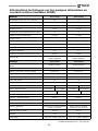
Model Series ATEX ANZEx IEx
94/9/EC
AS 2380.1 AS 2380.2
AS 1939
IEC 60079-0 IEC
60079-1
FR1200GE X X X
FR2400GE X X X
FR4200GE X X X
FR4400GE X X X
Certification Date 24-May-12 30-May-12 31-Aug-12
94/9/EC (until April 19, 2016), and 2014/34/EU (after April 20,2016): Equipment and Protective Systems Intended
for Use In Potentially Explosive Atmospheres.
AS2380.1: Electrical Equipment for Explosive Atmospheres - Explosion - Protection Techniques - Part 1: General
Requirements.
AS2380.2: Electrical Equipment for Explosive Atmospheres - Explosion - Protection Techniques - Part 2: Flameproof
enclosure d. (Class I Group D)
AS1939: Degrees of Protection Provided by Enclosures of Electrical Equipment.
IEC 60079-0: Explosive Atmospheres - Part 0: Equipment - General Requirements.
IEC 60079-0: Explosive Atmospheres - Part 1: Equipment Protection by Flameproof Enclosures d. (Class I Group D)
Motor Tag Information
The Motor Tag on your Fill-Rite pump
contains important technical and
performance information. Be certain this
label remains affixed to the pump at all
times.
Date stamp location
La page est en cours de chargement...
La page est en cours de chargement...
La page est en cours de chargement...
La page est en cours de chargement...
La page est en cours de chargement...
La page est en cours de chargement...
La page est en cours de chargement...
La page est en cours de chargement...
La page est en cours de chargement...
La page est en cours de chargement...
La page est en cours de chargement...
La page est en cours de chargement...
La page est en cours de chargement...
La page est en cours de chargement...
La page est en cours de chargement...
La page est en cours de chargement...
La page est en cours de chargement...
La page est en cours de chargement...
La page est en cours de chargement...
La page est en cours de chargement...
La page est en cours de chargement...
La page est en cours de chargement...
La page est en cours de chargement...
La page est en cours de chargement...
La page est en cours de chargement...
La page est en cours de chargement...
La page est en cours de chargement...
La page est en cours de chargement...
La page est en cours de chargement...
La page est en cours de chargement...
La page est en cours de chargement...
La page est en cours de chargement...
La page est en cours de chargement...
La page est en cours de chargement...
La page est en cours de chargement...
La page est en cours de chargement...
La page est en cours de chargement...
La page est en cours de chargement...
La page est en cours de chargement...
La page est en cours de chargement...
La page est en cours de chargement...
La page est en cours de chargement...
La page est en cours de chargement...
La page est en cours de chargement...
La page est en cours de chargement...
La page est en cours de chargement...
La page est en cours de chargement...
La page est en cours de chargement...
La page est en cours de chargement...
La page est en cours de chargement...
La page est en cours de chargement...
La page est en cours de chargement...
La page est en cours de chargement...
La page est en cours de chargement...
La page est en cours de chargement...
La page est en cours de chargement...
La page est en cours de chargement...
La page est en cours de chargement...
La page est en cours de chargement...
La page est en cours de chargement...
-
 1
1
-
 2
2
-
 3
3
-
 4
4
-
 5
5
-
 6
6
-
 7
7
-
 8
8
-
 9
9
-
 10
10
-
 11
11
-
 12
12
-
 13
13
-
 14
14
-
 15
15
-
 16
16
-
 17
17
-
 18
18
-
 19
19
-
 20
20
-
 21
21
-
 22
22
-
 23
23
-
 24
24
-
 25
25
-
 26
26
-
 27
27
-
 28
28
-
 29
29
-
 30
30
-
 31
31
-
 32
32
-
 33
33
-
 34
34
-
 35
35
-
 36
36
-
 37
37
-
 38
38
-
 39
39
-
 40
40
-
 41
41
-
 42
42
-
 43
43
-
 44
44
-
 45
45
-
 46
46
-
 47
47
-
 48
48
-
 49
49
-
 50
50
-
 51
51
-
 52
52
-
 53
53
-
 54
54
-
 55
55
-
 56
56
-
 57
57
-
 58
58
-
 59
59
-
 60
60
-
 61
61
-
 62
62
-
 63
63
-
 64
64
-
 65
65
-
 66
66
-
 67
67
-
 68
68
-
 69
69
-
 70
70
-
 71
71
-
 72
72
-
 73
73
-
 74
74
-
 75
75
-
 76
76
-
 77
77
-
 78
78
-
 79
79
-
 80
80


dans d''autres langues
Documents connexes


Autres documents
-
Hillsdale Furniture Lancaster Wood 4 Drawer Dresser Le manuel du propriétaire
-
Ingersoll-Rand AF12 Series General Information Manual
-
 Piusi EX 50 Use And Maintenance
-
-
 Lumax LX-1378 Manuel utilisateur
-
 SOTERA SS445BX727 Mode d'emploi
-
MYERS MW & ME Series Submersible Effluent Pumps & Sewage Pumps Le manuel du propriétaire
-
STA-RITE SN Series, HN Series Shallow Well Jet Pumps Le manuel du propriétaire
-
Goulds Pumps SRL Series Mode d'emploi


