La page est en cours de chargement...

1-K
Kerosene
Congratulations!
You have purchased the finest kerosene portable forced air construction heater available.
Your new L.B. White heater incorporates the benefits from the most experienced
manufacturer of heating products using state-of-the-art technology.
We, at L.B. White, thank you for your confidence in our products and welcome any
suggestions or comments you may have...call us, toll-free, at (800) 345-7200.
Owner's Manual and Instructions
Tradesman Kerosene Heaters
ATTENTION ALL USERS
This heater has been tested and evaluated by C.S.A. International in accordance with
the requirements of Standard UL 733 and ANSI A10.10-1990, CAN/CSA B140.0-03
and CSA B140.8 - 1967 and is listed and approved as a Kerosene forced-air
construction heater with application for the temporary heating of buildings under
construction, alteration, or repair. If you are considering using this product for any
application other than its intended use, then please contact the L.B. White Co., Inc.
MODELS OUTPUT (BTUH) FUEL
CP125AK 125,000
CP170AK 170,000
CP210AK 210,000
Certification by:
150-26902


WARNING
Fire and Explosion Hazard
■ Not for home or recreational vehicle use.
■ Installation of this heater in a home or recreational
vehicle may result in a fire or e
xplosion.
■ Fire or explosions can cause property damage or loss
of life.
FOR YOUR SAFETY
Do not store or use gasoline or other flammable vapors
and liquids in the vicinity of this or any other appliance.
WARNING
Fire and Explosion Hazard
■ Keep solid combustibles a safe distance away from
the heater.
■ Solid combustibles include w
ood, paper, or plastic
products, building materials and dust.
■ Do not use the heater in spaces which cont
ain or may
contain volatile or airborne combus
tibles.
■ Volatile or airborne combustibles include gasoline,
solvents, paint thinner, dus
t particles or unknown
chemicals.
■ Failure to follow these instructions may result in a fire
or explosion.
■ Fire or explosions can lead to proper
ty damage,
personal injury or loss of lif
e.
GENERAL HAZARD WARNING
■ Failure to comply with the precautions and instructions provided with this heater, can result in:
—Dea
th
— Serious bodily injury or burns
— Property damage or loss from fire or explosion
— Asphyxiation due to lack of adequate air supply or carbon monoxide poisoning
— Electrical shock
■ Read this Owner’s Manual before installing or using this product.
■ Only properly-trained service people should repair or install this heater.
■ Save this Owner’s Manual for future use and reference.
■ Owner’s Manuals and replacement labels are available at no charge. For assistance, contact L.B. White at 800-
345-7200.
2

SECTION PAGE
General Information . . . . . . . . . . . . . . . . . . . . . . . . . . . . . . . . . . . . . . . . . . . . . . . . . . . . . . . . . . . . . . . . . . .3
Heater Specifications . . . . . . . . . . . . . . . . . . . . . . . . . . . . . . . . . . . . . . . . . . . . . . . . . . . . . . . . . . . . . . . . . .4
Safety Information
Hazard Definitions . . . . . . . . . . . . . . . . . . . . . . . . . . . . . . . . . . . . . . . . . . . . . . . . . . . . . . . . . . . . . . . . .5
General Safety Information . . . . . . . . . . . . . . . . . . . . . . . . . . . . . . . . . . . . . . . . . . . . . . . . . . . . . . . . .5
Installation & Assembly
Heater Specifications . . . . . . . . . . . . . . . . . . . . . . . . . . . . . . . . . . . . . . . . . . . . . . . . . . . . . . . . . . . . . .7
Assembly . . . . . . . . . . . . . . . . . . . . . . . . . . . . . . . . . . . . . . . . . . . . . . . . . . . . . . . . . . . . . . . . . . . . . . . .8
Operation
Overview of Heater Design . . . . . . . . . . . . . . . . . . . . . . . . . . . . . . . . . . . . . . . . . . . . . . . . . . . . . . . . . .9
The Safety System . . . . . . . . . . . . . . . . . . . . . . . . . . . . . . . . . . . . . . . . . . . . . . . . . . . . . . . . . . . . . . . . .9
Fuel Specifications . . . . . . . . . . . . . . . . . . . . . . . . . . . . . . . . . . . . . . . . . . . . . . . . . . . . . . . . . . . . . . . .9
Fueling Your Heater . . . . . . . . . . . . . . . . . . . . . . . . . . . . . . . . . . . . . . . . . . . . . . . . . . . . . . . . . . . . . . .10
To Start Heater . . . . . . . . . . . . . . . . . . . . . . . . . . . . . . . . . . . . . . . . . . . . . . . . . . . . . . . . . . . . . . . . . .10
To Shutdown Heater . . . . . . . . . . . . . . . . . . . . . . . . . . . . . . . . . . . . . . . . . . . . . . . . . . . . . . . . . . . . . .10
To Restart Heater . . . . . . . . . . . . . . . . . . . . . . . . . . . . . . . . . . . . . . . . . . . . . . . . . . . . . . . . . . . . . . . .10
Extra Electrical Outlet . . . . . . . . . . . . . . . . . . . . . . . . . . . . . . . . . . . . . . . . . . . . . . . . . . . . . . . . . . . . .10
Longterm Storage of Your Heater . . . . . . . . . . . . . . . . . . . . . . . . . . . . . . . . . . . . . . . . . . . . . . . . . . .11
Maintenance
Fuel Tank . . . . . . . . . . . . . . . . . . . . . . . . . . . . . . . . . . . . . . . . . . . . . . . . . . . . . . . . . . . . . . . . . . . . . . .12
Air Input Filter . . . . . . . . . . . . . . . . . . . . . . . . . . . . . . . . . . . . . . . . . . . . . . . . . . . . . . . . . . . . . . . . . . .12
Air Output /Lint Filter . . . . . . . . . . . . . . . . . . . . . . . . . . . . . . . . . . . . . . . . . . . . . . . . . . . . . . . . . . . . .12
Fan Blades . . . . . . . . . . . . . . . . . . . . . . . . . . . . . . . . . . . . . . . . . . . . . . . . . . . . . . . . . . . . . . . . . . . . . .12
Nozzle . . . . . . . . . . . . . . . . . . . . . . . . . . . . . . . . . . . . . . . . . . . . . . . . . . . . . . . . . . . . . . . . . . . . . . . . .13
Spark Plug . . . . . . . . . . . . . . . . . . . . . . . . . . . . . . . . . . . . . . . . . . . . . . . . . . . . . . . . . . . . . . . . . . . . . .14
Photocell . . . . . . . . . . . . . . . . . . . . . . . . . . . . . . . . . . . . . . . . . . . . . . . . . . . . . . . . . . . . . . . . . . . . . . .14
Fuel Filter . . . . . . . . . . . . . . . . . . . . . . . . . . . . . . . . . . . . . . . . . . . . . . . . . . . . . . . . . . . . . . . . . . . . . . .15
Pump Pressure Adjustment . . . . . . . . . . . . . . . . . . . . . . . . . . . . . . . . . . . . . . . . . . . . . . . . . . . . . . . .15
Replacing Fuse . . . . . . . . . . . . . . . . . . . . . . . . . . . . . . . . . . . . . . . . . . . . . . . . . . . . . . . . . . . . . . . . . .16
Wiring Diagram . . . . . . . . . . . . . . . . . . . . . . . . . . . . . . . . . . . . . . . . . . . . . . . . . . . . . . . . . . . . . . . . . . . . . .17
Troubleshooting . . . . . . . . . . . . . . . . . . . . . . . . . . . . . . . . . . . . . . . . . . . . . . . . . . . . . . . . . . . . . . . . . . . . .18
Parts Identification
Parts Schematic (CP125AK & CP170AK) . . . . . . . . . . . . . . . . . . . . . . . . . . . . . . . . . . . . . . . . . . . . .19
Parts List (CP125AK & CP170AK) . . . . . . . . . . . . . . . . . . . . . . . . . . . . . . . . . . . . . . . . . . . . . . . . . . .20
Parts Schematic (CP210AK) . . . . . . . . . . . . . . . . . . . . . . . . . . . . . . . . . . . . . . . . . . . . . . . . . . . . . . .21
Parts List (CP210AK) . . . . . . . . . . . . . . . . . . . . . . . . . . . . . . . . . . . . . . . . . . . . . . . . . . . . . . . . . . . . .22
Parts Schematic (Handles/Wheels) . . . . . . . . . . . . . . . . . . . . . . . . . . . . . . . . . . . . . . . . . . . . . . . . .23
Warranty Information . . . . . . . . . . . . . . . . . . . . . . . . . . . . . . . . . . . . . . . . . . . . . . . . . . . . . . . . . . . . . . . . .24
Table of Contents
General Information
This Owner's Manual includes all options and accessories
commonly used on this heater.
When calling for technical service assistance, or for other
specific information, always have model number,
configuration number and serial number available. This
information is contained on the dataplate.
This manual will instruct you in the operation and care of
your unit. Have your qualified installer review this manual
with you so that you fully understand the heater and how it
functions.
The installation, repair, and servicing of the heater
requires continuing expert training and knowledge of
kerosene heaters and should not be attempted by anyone
who is not so qualified.
Contact your local L.B. White distributor or the L.B. White
Co., Inc. for assistance, or if you have any questions about
the use of the equipment or its application.
The L.B. White Co., Inc. has a policy of continuous product
improvement. It reserves the right to change
specifications and design without notice.
3

Heater Specifications
4
Model
Fuel Type
Max Input (BTUH)
Ventilation Air Required to Support Combustion
Pump Pressure (PSIG)
Fuel Consumption per Hour (gal)
Electrical Supply (Voltz/Hz/Phase)
SPECIFICATIONS CP125AK CP170AK CP210AK
Motor Characteristics
Amp Draw
Length x Width x Height
1-K, Kerosene
125,000 170,000 210,000
520 CFM 600 CFM 650 CFM
5.5 6.5 8.5
.95 1.3 1.6
Ball Bearing
1/5HP 3455 RPM 1/4HP 3430 RPM 1/3HP 3380 RPM
120/60/1
2.5 3.2 3.7
43
1
/2” x 23
29
/32” x 26
19
/32”
4 ft.
4 ft.
4 ft.
8 ft.
25 ft.
49 53 57
55 60 65
-20
o
F
Net Weight (lbs.)
Top
Sides
Back
Blower Outlet
Bulk Fuel Storage Container
CONTINUOUS
OPERATION
Minumum Safe
Distances From
Nearest
Combustible
Materials
Shipping Weight (lbs.)
Minimum Ambient Temperature
in which Heater may be used
37
1
/2” x 22
13
/32” x 24
29
/32”

Safety Information
HAZARD DEFINITIONS
DANGER
Indicates an imminently hazardous situation which, if not
avoided WILL result in death or serious injury.
WARNING
Indicates a potentially hazardous situation which, if not
avoided, COULD result in death or serious injury.
CAUTION
Indicates a potentially hazardous situation which, if not
avoided, MAY result in minor or moderate injury.
WARNING
Before using this heater, please read this USER’S
MANUAL very carefully. This USER’S MANUAL has been
designed to instruct you as to the proper manner in which
to assemble, maintain, store, and most importantly, how
to operate the heater in a safe and efficient manner.
WARNING
Never leave the heater unattended while burning!
DANGER
Improper use of this heater can result in serious injury or
death from burns, fire, explosion, electrical shock, and/or
carbon monoxide poisoning.
5
GENERAL SAFETY INFORMATION

6
■
Use this heater only in well ventilation areas. Provide proper
ventilation. See heater specifications (page 4).
■
Never use this heater in living or sleeping areas.
■
Carbon Monoxide Poisoning: Early signs of carbon
monoxide poisoning resemble flu-like symptoms such as
headaches, dizziness, and/or nausea. If you have these
symptoms, your heater may not be working properly.
■
Get fresh air at once! Have the heater serviced.
■
People with breathing problems should consult a physician
before using the heater.
■ Keep all combustible materials away from this heater.
Minimum Clearances
Outlet 8 feet (250 cm)
Sides, Top and Rear 4 feet (125 cm)
■ NEVER use fuels such as gasoline, benzene, paint thinners,
or other oil compounds in this heater
(RISK OF FIRE OR EXPLOSION).
■ NEVER use this heater where flam mable vapors may be
present.
■NEVER refill the heater’s fuel tank while heater is operating
or still hot. This heater is EXTREMELY HOT while in
operation.
■ NEVER block air inlet (rear) or air outlet (front) of heater.
■NEVER use duct work in front or at rear of heater.
■
NEVER move or handle heater while still hot.
■NEVER transport heater with fuel in
its tank.
■ When used with optional thermostat or if equipped with a
thermostat, the heater may start at any time.
■ ALWAYS locate heater on a stable and level surface.
■Use 1-K kerosene in this heater. #1 fuel oil is a suitable
substitute.
■ Bulk fuel storage should be a minimum of 25 ft. from
heaters, torches, portable generators, or other sources of
ignition. All fuel storage should be in accordance with federal,
state, or local authorities having jurisdiction.
WARNING
Risk of Electric Shock!
WARNING
Risk of CO Poisoning!
WARNING
Risk of Burns/Fire/Explosion!
GENERAL SAFETY INFORMATION (cont.)
■ Use only the electrical power (voltage and frequency)
specified on the model plate of the heater. Use only a
three prong, grounded outlet and extension cord.
■ ALWAYS install the heater so that it is not directly
exposed to water spray, rain, dripping water, or wind.
■ ALWAYS unplug the heater when not in use.
CALIFORNIA RESIDENTS:
This heater produces carbon
monoxide, which is listed by the State of California as a
reproductive toxin under Proposition 65.
MASSACHUSETTS RESIDENTS:
Massachusetts state law
prohibits the use of this heater in any building which is used
in whole or in part for human habitation. Use of this heating
device in Massachusetts requires local fire dept. permit
(M.E.L.C. 148, Section 10A).
CANADIAN RESIDENTS:
Use of this heater shall be in
accor dance with authorities having juris diction and CSA
Standard B139.
NEW YORK CITY RESIDENTS:
For use only at construction
sites in accordance with applicable NYC codes under NYCFD
certificate of approval #5034 and 5037

Installation and Assembly Instructions
HEATER SPECIFICATIONS
47
Introduction
Please read this USER’S MANUAL carefully. It will show you
how to assemble, maintain and operate this heater safely
and efficiently to obtain the full benefits of its many
features.
Consumer: Retain these instructions for future reference.
Unpacking
1. Remove all packing items applied to heater for
shipment.
2. Remove all items from carton.
3. Check all items for shipping damage.
If heater is damaged, promptly inform dealer where you
purchased heater.
Dimensions
Figure 1 – Heater Dimensions
Product Features
CP125AK CP170AK
CP210AK
Height 24 29/32” 26 19/32”
Length 37 1/2” 43 1/2”
Width 22 13/32” 23 29/32”
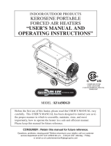
Hot Air Outlet
Lower Shell
Fuel
Gauge
Fuel Cap
Lamp
Side Cover
Room Temp. Display
Thermostat
Knob
Power/Reset Switch
Power Cord
Cord Wrap
Pressure Gauge
Handle Rear
Handle Front
Upper Shell
Electric Outlet
Figure 2 – Features
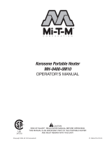
Figure 3 – Assembly
Front Handle
Hot Air Outlet
Wheel (pneumatic
Flt Washer
Wheel Cap
Fuel Tank
Flange
Cotter Pin
Nut
Wheel Support Frame
Flange Screw
Cord Wrap
Screw S
Screw L
Nut
Rear Handle
Air Inlet
Axle
Wheel Bushing
Wheel Tube Valve
Washer

Front Handle
Rear Handle
Axle
Wheel Support Frame
CP125AK / CP170AK / CP210AK
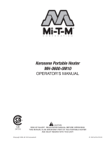
Figure 4 – Component Identification
Model CP125AK CP170AK CP210AK
Wheel Support Frame Yes Yes Yes
Wheels Yes Yes Yes
Cap-Wheel Yes Yes Yes
Front-Handle Yes Yes Yes
Rear-Handle Yes Yes Yes
Axle Yes Yes Yes
Cord Wrap Yes Yes Yes
Hardware Kit Yes Yes Yes
Installation and Assembly Instructions
ASSEMBLY
TOOLS REQUIRED
- Medium Phillips screwdriver.
- M5 open, or adjustable wrench.
- Long nose pliers.
1. Slide axle through wheel support frame. Install wheel bushings and wheels on axle.
NOTE:
When installing wheels, tube valve should face out from support frame (Figure 3).
2. Place flat washers and cotter pin on axle ends and bend cotter pins with long nose pliers to secure.
3. Place wheel cap on flat washers and put wheel cap in flat washers end.
4. Place heater on wheel support frame. Make sure the air inlet end (rear) of heater is over wheels. Align the holes on fuel
tank flange. Insert screws through handles (front and rear), fuel tank flange, and wheel support frame as shown in
Figure 4 and attach and nut finger tight after each screw is inserted.
5. After all screws are inserted, tighten nuts firmly.
6. Align the hole on the handle (front and rear) with the mounting hole on the cord wrap.
7. Insert screws through cord wrap, handles as shown in Figure 4 and attach nut finger tight after each screw is
inserted.
8. After all screws are inserted, tighten nuts firmly.
WARNING
Fire or explosion hazard!
■ Do not operate heater without support frame fully
assembled to tank.
48
Wheel Caps
Washers
Cotter Pins
Flange Screws
Nuts
Bushings
Screws L & S
Wheels
Washers
Wheel Caps

Figure 5 – Overview of Heater Design
FUEL SPECIFICATIONS
KEROSENE (1-K)
For optimal performance of this heater, it is strongly suggested
that 1-K kero sene be used. 1-K kerosene has been refined to
virtually eliminate contami nants, such as sulfur, which can
cause a rotten egg odor during the operation of the heater.
However, #1 or #2 fuel oil (diesel fuel) may also be used if 1-K
kerosene is not available. B
Be advised that these fuels do not
burn as clean as 1-K kerosene, and care should be taken to
provide more fresh air ventilation to accommodate any added
contaminants that may be added to the heated space.
OPERATION
OVERVIEW OF HEATER DESIGN
Fuel System:
This heater is equipped with an electric air pump
that forces air through the air line connected to the fuel
intake, and then through a nozzle in the burner head. When
air passes in front of the fuel intake, it causes fuel to rise from
the tank and into the burner nozzle.
This fuel and air mixture is then sprayed into the combustion
chamber in a fine mist.
SureFire Ignition:
The electronic ignitor sends voltage to a
specially designed spark plug. The spark plug ignites the fuel
and air mixture described above.
The Air System:
The heavy duty motor turns a fan that forces
air into and around the combustion chamber. Here, the air is
heated and then forced out the front of the heater.
THE SAFETY SYSTEM
Temperature Limit Control:
This heater is equipped with a
Temperature Limit Control designed to turn the heater off
should the internal temperature rise to an unsafe level. If this
device activates and turns your heater off, it may require
service.
Once the temperature falls below the reset temperature, you
will be able to start your heater.
Electrical System Protection:
This heater’s electrical system is
protected by a fuse mounted to the PCB Assembly that protects
it and other electrical components from damage. If your heater
fails to operate, check this fuse first and replace as needed.
Refer to Specification chart on page 4.
Flame-Out Sensor:
Utilizes a photocell to monitor the flame in
burn chamber during normal operation. It will cause the heater
to shut off should the burner flame extinguish.
Model Internal Shut-off Temp.
+/-10 Degrees
Reset Temp.
+/-10 Degrees
CP125AK/CP170AK
230
O
F/110
O
C 194
O
F/90
O
C
CP210AK
194
O
F/90
O
C 140
O
F/60
O
C
49
WARNING!
Fire and explosion hazard!
■ Kerosene should only be stored in a blue container that is
clearly mark ed “kerosene”. Never store kero sene in a red
container. Red is associ ated with gasoline.
■ NEVER store kerosene in the living space. Kerosene should
be stored in a well ventilated area outside the living area.
■ NEVER use fuel such as gasoline, benzene, alcohol, white
gas, camp stove fuel, paint thinners, or other oil
compounds in this heater (THESE ARE VOLATILE FUELS
THAT CAN CAUSE A FIRE OR EXPLOSION).
■ NEVER store kerosene in direct sunlight or near a source of
heat.
■ NEVER use kerosene that has been stored from one
season to the next. Kerosene deteriorates over time. OLD
KEROSENE WILL NOT BURN PROPERLY IN THIS HEATER.
■ Use 1-K kerosene in this heater. #1 fuel is a suitable
substitute.

FUELING YOUR HEATER
Never fill the heater fuel tank in the living space: fill the
tank outdoors.
Do not overfill your heater and be sure heater is level.
IMPORTANT:
REGARDING FIRST IGNITION OF HEATER. The
first time you light the heater, it should be done
OUTDOORS. This allows the oils, etc., used in
manufacturing heater to be burned off outside.
TO START HEATER
1. Fill fuel tank with kerosene or No. 1 fuel oil.
2. Attach fuel cap.
3. Plug power cord into three prong, grounded extension
cord. Extension cord must be at least six feet long.
- Extension Cord Wire Size Requirements:
- 6 to 10 feet (1.8 to 3 meters) long,
use 18 AWG conductor.
- 11 to 100 feet (3.4 to 30.53 meters) long, use 16
AWG conductor.
- 101 to 200 feet (30.8 to 61 meters) long, use 14
AWG conductor.
4. Turn thermostat control knob to desired setting and
push power switch to “ON” position. Power lamp will
light and heater will start.
NOTE:
Room Temp. display indicates as following:
- When room temp. is less than 0
o
F: “lo”.
- When room temp. is between 0
o
F and 99
o
F:
Indicates in figure.
- When room temp is greater than 99
o
F: “Hi”
If heater does not start, the thermostat setting may be too
low. Turn THERMOSTAT CONTROL KNOB to higher position
to start heater. If heater still does not start, turn power
switch to “OFF” and then to “ON” position (See Figure 6). If
heater still does not start, see Troubleshooting on page 18.
NOTE:
The major electrical components of this heater are
protected by a safety fuse mounted to the PCB board. If
your heater fails to start, check this fuse first and replace
as necessary. You should also check your power source to
insure that proper voltage and frequency are being supplied to
the heater.
TO SHUT DOWN HEATER
Turn switch to “OFF” and unplug power cord.
TO RESTART HEATER
1. Wait 10 seconds after stopping heater.
2. Repeat steps under, “TO START HEATER.”
EXTRA ELECTRICAL OUTLET
WARNING
Fire and explosion hazard!
■ Never refill fuel tank when heater is operating or
still hot.
OPERATION (cont.)
Power/Reset
Switch
Lamp
Thermostat
Control Knob
Room Temp. Display
Figure 6 – Controls
Cover
Electric Outlet
Figure 7 – Electric Outlet
WARNING
SHOCK HAZARD!
■ Always cover electric outlet when not in use. Don’t plug and
use an appliance of more than 5A current in this outlet.
410

LONG-TERM STORAGE OF YOUR HEATER
FUEL TANK DRAIN
1. Remove drain plug from rear bottom side of fuel tank by
pulling plug grip downward and drain. See Figure 8.
2. Using a small amount of kerosene, swirl and rinse the
inside of the tank.
NEVER MIX WATER WITH KEROSENE, as it will cause rust inside
the tank. Pour the kerosene out, making sure that you remove it
all.
IMPORTANT:
Do not store kerosene over summer for use during
next heating season. Using old fuel may damage heater.
3. Reinstall drain plug as follows:
- Insert plug’s seal head fully into drain hole so that flange is
flush
to tank’s bottom. See Figure 9.
- Insert seal cap fully into head hole so that cap flange is
flush to head flange. See Figure 9.
IMPORTANT:
Reinstall plug fully into hole in tank; otherwise it
will not seal completely.
- Make sure storage place is free of dust and corrosive fumes.
- Store the heater in the original box with the original packing
material and keep USER’S MANUAL with heater.
OPERATION (cont.)
Figure 8 – Drain Plug Removal
Drain Plug
Plug Grip
Rear Bottom
Side Fuel Tank
F
Figure 9 – Drain Plug Reinstall
Drain Hole
Fuel Tank
Seal Head
Head Flange
Head Flange
Head Hole
Seal Cap
Cap Flange
411

FUEL TANK
Flush every 200 hours of operation or as needed (See Long-
term Storage, page 11).
AIR INTAKE FILTER
WASH AND DRY WITH SOAP AND WATER EVERY 500 HOURS
OF OPERATION, OR AS NEEDED.
- Remove screws along each side of heater using medium
Phillips screwdriver.
- Lift off upper shell.
- Remove fan guard.
- Wash or replace air intake filter.
- Reinstall fan guard and upper shell.
AIR OUTPUT FILTER, LINT FILTER
REPLACE EVERY 500 HOURS OF OPERATION OR ONCE A
YEAR
- Remove upper shell and fan guard (See Air Intake Filter
Figure 10).
- Turn air pressure gauge counter-clockwise and remove.
- Remove end filter cover screws using medium Phillips
screwdriver.
- Remove end filter cover.
- Replace air output and lint filter.
- Reinstall end filter cover and air pressure gauge.
- Reinstall fan guard and upper shell.
FAN BLADES
CLEAN EVERY SEASON OR AS NEEDED
- Remove upper shell (See Air Intake Filter).
- Use M6 Allen wrench to loosen set screw which holds fan
blade to motor shaft.
- Slip fan blade off motor shaft.
- Clean fan blade using soft cloth moistened with kerosene
or solvent.
- Dry fan blade thoroughly.
- Reinstall fan blade to motor shaft.
- Place fan blade hub flush with end of motor shaft.
- Place set screw on flat of shaft.
- Tighten screw firmly (40-50 inch-pounds/4.5-5.6 N-m).
Reinstall upper shell.
Screw
Air Pressure Gauge
Lint Filter
Air Output
Filter
End Filter
Cover
Air Intake
Filter
Figure 11 – Filter Assembly
Figure 10 – Air Filter Access
Screw
Upper Shell
Air Intake Filter
Fan Guard
MAINTENANCE
USE ORIGINAL EQUIPMENT REPLACE MENT PARTS. Use of third-party or other alternate components will void warranty and
may cause unsafe operating conditions.
WARNING
Fire or explosion hazard!
■ Never service heater while it is plugged in or while hot!
Figure 12 – Fan Assembly
Set Screw
Motor Shaft
Fan Blade
Motor
Flush
412

NOZZLE
CLEAN NOZZLE AS NEEDED
(For Models CP125AK and CP170AK only)
- Remove upper shell (See Air Intake Filter, page 12).
- Remove fan blade (See Fan Blades).
- Remove fuel and air line hoses from burner head.
- Remove ignitor wire from spark plug.
- Remove three screws using medium Phillips screwdriver
and remove burner head from combustion chamber.
- Remove spark plug from burner head using medium
Phillips screwdriver.
- Carefully remove nozzle from burner head using 5/8”
socket wrench.
- Blow compressed air through face of nozzle
(This will remove any dirt).
- Reinstall nozzle into burner head and tighten firmly (80-
100 inch-pounds).
- Reinstall spark plug into burner head.
- Attach burner head to combustion chamber.
- Attach ignitor wire to spark plug. Attach fuel and air line
hoses to burner head.
- Reinstall fan blade and upper shell.
(For Model CP210AK only)
- Remove upper shell (See Air Intake Filter, page 12).
- Remove fan blade (See Fan Blades).
- Remove fuel and air line hoses from adapter nozzle.
- Remove ignitor wire from spark plug.
- Remove four screws using medium Phillips screwdriver and
remove bracket burner from combustion chamber.
- Remove spark plug from bracket spark using medium Phillips
screwdriver.
- Carefully remove nozzle from adaptor nozzle using 5/8”
socket wrench.
- Blow compressed air through the face of nozzle (this will
remove any dirt).
- Reinstall nozzle into adaptor-nozzle and tighten firmly (80-
110 inch-pounds).
- Reinstall spark plug in bracket spark.
- Attach bracket burner to combustion chamber.
- Attach ignitor wire to spark plug.
- Attach fuel and air line hoses to adaptor nozzle.
- Reinstall fan blade and upper shell.
413
Figure 13 – Nozzle Replacement For Models CP125AK and CP170AK
Combustion Chamber
Screw
Ignitor Wire
Burner Head
Fuel Line Hose
Air Line Hose
Nozzle Face
Nozzle
Air Line Fitting
Fuel Line Fitting
Burner Head
Spark Plug
MAINTENANCE (cont.)
F
Figure 14 – Nozzle Replacement CP210AK
Combustion Chamber
Screw
Ignitor Wire
Air Line Hose
Nozzle Face
Nozzle
Air Line Fitting
Fuel Line Fitting
Fuel Line Fitting
Bracket Burner
Bracket Burner
BracketSpark
Spark Plug
Spark Plug

MAINTENANCE (cont.)
SPARK PLUG
CLEAN AND REGAP EVERY 600 HOURS OF OPERATION OR
REPLACE AS NEEDED.
CLEAN AND REGAP EVERY 600 HOURS OF OPERATION OR
REPLACE AS NEEDED.
(For Models CP125AK and CP170AK only)
- Remove upper shell (See Air Intake Filter, page 12).
- Remove fan (See Fan Blades).
- Remove ignitor wire from spark plug.
- Remove spark plug from burner head using medium Phillips
screwdriver.
- Clean and regap spark plug electrodes to
.140” (3.5 mm) gap.
- Reinstall spark plug into burner head.
- Attach ignitor wire to spark plug.
- Reinstall fan and upper shell.
(For Model CP210AK only)
- Remove upper shell (See Air Intake Filter, page 12).
- Remove fan (See Fan Blades).
- Remove ignitor wire from spark plug.
- Remove spark plug from bracket spark using medium Phillips
screwdriver.
- Clean and regap spark plug electrodes to
.140” (3.5 mm) gap.
- Reinstall spark plug into bracket spark.
- Attach ignitor wire to spark plug.
- Reinstall fan and upper shell.
F
Figure 15 – Spark Plug Replacement
Spark Plug
Ignitor Wire
Burner Head
F
Figure 16– Spark Plug Replacement
Bracket Burner
Bracket Spark
Spark Plug
PHOTOCELL
CLEAN PHOTOCELL ANNUALLY OR AS NEEDED.
- Remove upper shell (See Air Intake Filter, page 12)
- Remove fan (See Fan Blades)
- Remove photocell from its mounting bracket.
- Clean photocell lens with cotton swab.
TO REPLACE: Remove side cover near power switch.
- Disconnect wires from power switch and remove
side cover.
- Disconnect wires from circuit board and remove photocell.
- Install new photocell and attach wires to circuit board.
- Replace switch wires to power switch and side cover.
- Replace fan and upper shell.
Power
Switch
Switch
Wires
PhotocellWire
Bracket
Install Photocell
Photocell
Lens
Incorrect
Correct
Side Cover
Screw
F
Figure 17 – Photocell Replacement
414

FUEL FILTER
CLEAN OR REPLACE TWICE PER HEATING SEASON OR AS
NEEDED.
- Remove side cover screws using medium Phillips
screwdriver.
- Disconnect switch wires from power switch and remove
side cover.
- Pull fuel line off fuel filter neck.
- Turn fuel filter clockwise 90 degrees and pull to remove.
- Wash fuel filter with clean fuel and replace in tank.
- Attach fuel line to fuel filter neck.
- Reinstall side cover.
415
MAINTENANCE (cont.)
F
Figure 18 – Fuel Filter Replacement
Fuel Filter
Fuel Line
Switch Wires
Power Switch
Side Cover
Screw
PUMP PRESSURE ADJUSTMENT
- Start heater (See “Operation”, page 10).
- Allow motor to reach full speed.
- Adjust pressure (using flat blade screwdriver).
- Turn relief valve clockwise to increase pressure.
- Turn relief valve counterclockwise to decrease pressure.
- Set pump pressure to correct pressure for each model.
- Stop heater (see “Operation”, page 10).
NOTE:
USE ONLY ORIGINAL EQUIPMENT REPLACEMENT
PARTS. Use of alternate or third party components will void
warranty and may cause an unsafe operating condition.
F
Figure 19 – Adjusting Pump Pressure
Pressure Gauge
Relief Valve
Flat blade
Screwdriver
Model Pump Pressure
CP125AK 5.5 PSI
CP170AK 6.5 PSI
CP210AK 8.5 PSI

416
REPLACING FUSE
NOTE:
The heater is fuse protected. If
your heater fails to ignite, DO NOT RETURN YOUR HEATER TO THE
STORE.
Please follow the simple instructions below to inspect and change
the fuse.
- Unplug heater.
- Remove side cover screws using medium Phillips screwdriver.
- Disconnect switch wires from power switch.
- Remove fuse from fuse holder (See Figure 16).
- Replace fuse with enclosed fuse.
- Replace switch wires to power switch.
- Replace side cover.
NOTE:
Specified fuse rating: AC 125/8A
WARNING
Burn hazard!
■ SHOCK HAZARD. To prevent presonal injury, unplug the
power cord before replacing fuse.
Fuse Holder
Fuse
Screw
Side Cover
Power Switch
Switch Wire
MAINTENANCE (cont.)
Figure 20 – Replacing Fuse

417
WIRING DIAGRAM
Figure 21 – Wiring Diagram Models CP125AK, CP170AK, CP210AK
CP125AK
CP170AK
CP210AK

Symptom Possible Cause(s) Corrective Action
Heater ignites but MAIN PCB
assembly shuts heater off after a
short period of time. (Indicator
Lamp is flickering and room temp.
display indicates “E1”)
Heater will not ignite but motor
runs for a short period of time.
(Indicator Lamp is flickering and
room temp. display indicates “E1”)
Fan does not turn when heater is
plugged in and power switch was
in the “ON” position. (Indicator
Lamp is on or flickering)
(Indicator Lamp is flickering and
room temp. display indicates “E2”)
(Indicator Lamp is flickering and
room temp. display indicates “E3”)
Heater will not turn-on (Indicator
Lamp is off)
1. Wrong pump pressure
2. Dirty Air Output, Air Intake or Lint Filter
3. Dirty Fuel Filter
4. Dirt in Nozzle
5. Dirt Photocell Lens
6. Photocell Assembly not Properly Installed (not
seeing the flame)
7. Bad electrical connection between photocell and
MAIN PCB Assembly
8. Defective photocell
1. No fuel in tank
2. Wrong pump pressure
3. Carbon deposits on spark plug and/or improper
gap
4. Dirty fuel filter
5. Dirt in Nozzle
6. Water in fuel tank
7. Bad electrical connection between igniter and
MAIN PCB Assembly
8. Igniter wire is not attached to spark plug
1. Thermostat setting is too low
2. Bad electrical connection between motor and MAIN
PCB Assembly
1. Room Temp. sensor disconnected
2. Sensor Failure
Thermostat switch failure
1. Temperature limit safety device is overheated
2. No electrical power
3. Blown fuse
4. Bad electrical connection between temperature
limit safety device and
PCB board
1. See Pump Pressure Adjustment, page 15
2. See Air Output, Air Intake and Lint Filters, page 12
3. See Fuel Filter, page 15
4. See Nozzle, page 13
5. Clean Photocell Lens, page 14
6. Make sure photocell boot is properly seated in
bracket, Page 14
7. Check electrical components. See Wiring Diagrams,
page 17
8. Replace Photocell, page 14
1. Fill tank with kerosene
2. See Pump Pressure Adjustment, page 15
3. See Spark Plug, page 14
4. See Fuel Filter, page 15
5. See Nozzle, page 13
6. Flush fuel tank with clean kerosene, page 11
7. Check electrical components. See Wiring Diagram,
page 17
8. Attach igniter to spark plug. See Spark Plug, page 14
1. Turn thermostat control knob to a higher setting
2. Check electrical connections. See Wiring Diagram,
page 17
1. Reconnect sensor. See Wiring Diagrams,
page 17
2. Replace sensor. See Wiring Diagram, page 17
Replace MAIN PCB
1. Turn power switch to “OFF” and allow to cool (about
10 min.)
2. Check to insure heater cord and extension cord are
plugged in. Check power supply
3. Replace safety fuse in PCB board. See Replacing
Fuse, page 16
4. Check electrical connections. See Wiring Diagrams,
page 17
Troubleshooting Chart
Troubleshooting
418

For Repair Parts,
call 1-800-345-7200
Please provide following information:
-Model number
-Serial number (if any)
-Part description and number as shown in parts list
PARTS SCHEMATIC (CP125AK & CP170AK)
Parts Identification
Figure 22– Repair Parts Illustration for Portable Oil-Fired Heaters Models CP125AK, CP170AK
1
7
2
11
3
8
6
22
23
18-1
18-2
18-3
18-4
18-5
18-8
18-6
18-9
18-10
18-7
24
19
4
12
25
16
10
21
20
18
17
15
14
15-1
15-2
15-3
15-4
13
5
9
26
419
/