Outdoor Leisure td101 Le manuel du propriétaire
- Taper
- Le manuel du propriétaire

For more information, visit www.desatech.com
WARNING: For
Outdoor Use Only
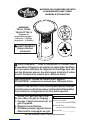
PROPANE/LP BISTRO TABLE
INFRARED PATIO HEATER
OWNER’S MANUAL
MODELS
TD101, TD103,
TD109 and TD111
Adjustable Temperature
Settings:
Low - 9,500 Btu
High - 16,000 Btu
FOR YOUR SAFETY
If you smell gas:
1.
Shut off gas to the appliance.
2. Extinguishanyopename.
3. If odor continues, immedi-
ately call your gas supplier.
Fill In For Your Records
Model No. ____________________
(Located on side panel)
Serial No. _____________________
(Located on side panel)
Date of Purchase _______________
WARNING: Read and understand this manual before
assembling, starting, or servicing heater. Improper use
of heater can cause serious injury, property damage, or
death. Keep this manual for future reference.
INSTALLER: Leave this manual with the appliance.
CONSUMER: Retain this manual for future reference.
FOR YOUR SAFETY
Donotstoreorusegasolineorotherammablevapors
and liquids in the vicinity of this or any other appliance.

www.desatech.com 118992-01F2
SAFETY INFORMATION
WARNING: This product con-
tains and/or generates chemicals
known to the state of California to
cause cancer or birth defects, or
other reproductive harm.
WARNING: Fire, burn, inha-
lation, and explosion hazard.
Keep solid combustibles, such
as building materials, wood, vi-
nyl siding, paper or cardboard,
a safe distance away from the
heater as recommended by the
instructions. Never use heater in
spaces which do or may contain
volatile or airborne combustibles,
or products such as gasoline, sol-
vents, paint thinner, dust particles
or unknown chemicals.
WARNING: Improper instal-
lation, adjustment, alteration,
service or maintenance can cause
injury, property damage, or death.
Read the installation, operating,
and maintenance instructions
thoroughly before installing or
servicing this equipment.
WARNING: For use only out-
doors in a well ventilated space.
Do not use heater indoors or in a
building or garage or any unven-
tilated or enclosed areas.
This heater is designed for use as an
infrared patio heater in accordance with
the applicable requirements CSA 5.90
U.S. Infrared Patio Heaters, CAN 1-2.23
Portable Infrared Heaters for Canada.
Other standards govern the use of fuel gases
and heating products for specic uses. Your
local authority can advise you about these.
The primary purpose of outdoor patio heaters
is to provide heating of residential and non-
residential spaces. Properly used, this heater
provides safe economical heating.
We cannot foresee every use which may be
made of our heaters. CHECK WITH YOUR
LOCAL FIRE SAFETY AUTHORITY IF YOU
HAVE QUESTIONS ABOUT HEATER USE.
Carbon Monoxide Poisoning: Some people are
more affected by carbon monoxide than oth-
ers. Early signs of carbon monoxide poisoning
resemble the flu, with headaches, dizziness,
and/or nausea. If you have these signs, the
heater may not be working properly. Get fresh
air at once! Have heater serviced.
Propane/LP Gas: Propane/LP gas is odorless.
An odor-making agent is added to propane/LP
gas. The odor helps you detect a propane/LP
gas leak. However, the odor added to pro-
pane/LP gas may fade. Propane/LP gas may
be present even though no odor exists.
Make certain you read and understand all
warnings. Keep this manual for reference. It
is your guide to safe and proper operation of
this heater.
Any guard or other protective
device removed for servicing
must be replaced prior to operat-
ing the heater.
Surface temperatures become very
hot when operating heater. Children
and adults should stay away to
avoid burns or clothing ignition.
Young children should be care-
fully supervised when they are
in the area of the heater.
TABLE OF CONTENTS
Safety Information ............................................... 2
Product Identication ........................................... 4
Unpacking............................................................ 4
Assembly ............................................................. 4
Operation ............................................................. 9
Troubleshooting ................................................. 10
Storage ...............................................................11
Maintenance .......................................................11
Specications .....................................................11
Illustrated Parts Breakdown and Parts List........ 12
Replacement Parts ............................................ 15
Technical Service............................................... 15
Accessory .......................................................... 15
Warranty Information ......................................... 16

www.desatech.com
118992-01F 3
Clothing or other flammable
materials should not be hung
from the heater, or placed on or
near heater.
Installation and repair should
bedoneby a qualiedservice
person. The heater should be
inspected before use and at least
annuallybyaqualiedservice
person. More frequent cleaning
may be required as necessary.
It is imperative that control
compartments, burners, and
circulating air passageways of
the heater be kept clean.
CAUTION: The gas pressure
regulator provided with this ap-
pliance must be used. This regu-
lator is set for an output pressure
of 11" W.C. (0.4 P.S.I.).
1. Install and use heater with care. Follow
all local ordinances and codes. In the ab-
sence of local ordinances and codes, refer
to the Standard for Storage and Handling
of Liqueed Petroleum Gas, ANSI/NFPA
58, CAN/-B149 Installation CODE. This
instructs on the safe storage and handling
of propane/LP gases.
2. Use only propane/LP gas set up for vapor
withdrawal in a 20 lb. cylinder. Cylinder must
be constructed and marked in accordance
with specications for propane/LP cylinders
of the U.S. Department of Transportation
(DOT). The cylinder must be provided with
a shutoff valve terminating in a propane/LP
supply cylinder valve outlet. The valve must
have external threads and marked “Use with
Type 1” and a safety relief device having a
direct communication with the vapor space
of the cylinder. The cylinder used must in-
clude a collar to protect the cylinder valve.
3. Keep appliance area clear and free from
combustible materials, gasoline, paint
thinner, and other flammable vapors and
liquids. Dust is combustible. Do not use
heater in areas with high dust content.
SAFETY INFORMATION
Continued
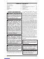
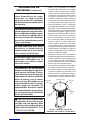
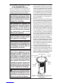
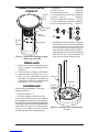
Figure 1 - Clearances from Combustibles
4. Spillage of combustible liquids into the
flame could cause a re.
5. Do not place combustible table cloths on
heater table. If table cloth is used, do not
allow any part of cloth to hang over edge
of table into heat outlet area.
6. Table becomes warm in operation.
7. Minimum heater clearances from perma-
nent combustible construction:
Front, Back and sides 6" (15.2 cm), Top
36" (0.91 m) (see Figure 1).
8. Before each use, check heater for leaks.
Never use an open flame to check for a
leak. Apply a mixture of liquid soap and
water to all joints. Bubbles forming show
a leak. Correct all leaks at once.
9. Keep propane/LP cylinder below 100° F
(38° C).
10. Use only the hose and factory preset
regulator provided with the heater. Do not
adjust regulator as gas leaks may occur.
11. Locate hose properly, keeping it out of
pathways where people may trip over it or
in areas where the hose may be subjected
to accidental damage. Keep hose away
from burner on inside of heater.
12. Check hose before each use of heater.
Disconnect hose with 9/16" wrench.
Check for tears and abrasions in hose and
on regulator. If highly worn or cut, replace
with hose specied by manufacturer be-
fore using heater.
13. Do not alter heater. Keep heater in its origi-
nal state. Do not use heater if altered.
14. Locate heater on stable and level surface.
15. Do not operate heater while sleeping or
leave heater unattended.
6"
(15.2 cm)
36" (0.91 m)
6"
(15.2 cm)
6"
(15.2 cm)
6"
(15.2 cm)

www.desatech.com 118992-01F4
SAFETY INFORMATION
Continued
UNPACKING
1. Remove all packing items applied to
heater for shipment.
2. Remove all items from carton.
3. Check all items for shipping damage. If
heater is damaged, promptly inform dealer
where you bought heater.
ASSEMBLY
Estimated assembly time: 55 minutes
Tools required:
• #2 Phillips screwdriver
• 8 mm and 10 mm Open end wrench
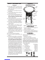
Hardware packet provided with heater may
contain more parts than needed for heater
assembly. Parts are referenced by designated
letter throughout assembly instructions. Hard-
ware packet contains the following (quantity
used in parenthesis):
Description Part Number
A 1" Screw (6) 119619-04
B 5 mm Washer (6) 119600-02
C 3/8" Screw (59) 119620-02
D 1 1/2" Screw (6) 119619-05
E 5 mm Hex Nut (6) NPC-3C
F 3/8" Machine Screw (6) 119742-01
G M6 Hex Nut (6) 119743-01
16. Never move, handle, or service a hot
or operating heater. Severe burns may
result. You must wait 20 minutes after
turning heater off.
17. To prevent injury, wear gloves when han-
dling heater.
18. Turn off heater valve and gas supply to
heater when not in use.
19. Use only original replacement parts. This
heater must use design-specic parts.
Do not substitute or use generic parts.
Improper replacement parts could cause
serious or fatal injuries.
20. Certain materials or items, when stored in
front of heater, will be subjected to radiant
heat and could be seriously damaged.
21. Shut heater off immediately if flashback
occurs (flame inside burner tube). Have
heater serviced.
22. Never attempt to use heater or any
components that have been damaged or
exposed to accidental re.
23. If you smell gas or suspect a leak, shut
off propane/LP cylinder valve at once.
Ventilate area. Do not strike a match or
create any flame or electric spark. Find
and correct leak before attempting to light
any appliance.
24. Do not block intake air openings.
25. Use correct pressure specications, see
page 11.
26. Propane/LP gas cylinder is not provided.
Use a 20 lb. propane/LP gas cylinder
marked propane. The cylinder supply sys-
tem must be arranged for vapor withdrawal.
The cylinder used must include a collar to
protect the cylinder valve. The cylinder must
be provided with a shutoff valve terminating
in a propane/LP gas supply cylinder valve
outlet specied, as applicable, for connec-
tion no. 510 in the Standard for Compressed
Gas Cylinders Valve Outlet and Inlet Con-
nections, ANSI/CGA-V-1, or connection no.
600 in the Compressed Gas Association’s
Limited Standard Cylinder Valve Outlet
Connection for Propane Small Valve Series
or combination propane/LP gas cylinder
valve and quick-disconnect assembly
complying with 1.16.5-c and a safety relief
device having a direct communication with
the vapor space of the cylinder.
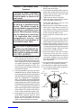
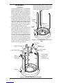
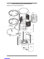
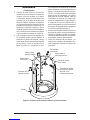
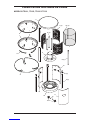
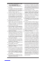
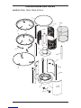
PRODUCT
IDENTIFICATION
Figure 2 - Infrared Patio Table Heater
Table
Top
Ignitor
Decorative
Grate
Emitter
Control
Knob
Guard
Rail
A
B
C
E
DF
G

www.desatech.com
118992-01F 5
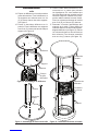
1. Locate table heater base and 3 lower table
support pillars with holes on one side only.
Making sure holes in pillars are oriented as
shown in Figure 3, slide support pillars into
base and attach with screws (A) and wash-
ers (B) through bottom 2 holes as shown.
2.
Position lower table panel and table control
panel onto base assembly as shown in Figure
4. Make certain lower table panel is on side
of base with wheels. Using bottom 3 sets of
holes only, attach panels to support pillars
with 12 screws (C) (see Figure 4). Attach
ignitor ground wire with 1 screw as shown in
Figure 4 (ignitor installed in step 4).
3. Top sets of screws (C) will insert through
panels, through support pillars, then into
pillar support connectors as shown in
Figure 4 (6 screws). Make sure pillar sup-
port connectors are oriented as shown in
Figure 4. The side of connectors with one
hole should be facing outside heater and
hole should be at the top. For support con-
nectors closest to front opening, second
screw will only install through panels and
support connectors. Second screw will
secure connector (see Figure 4).
Figure 3 - Installing Support Pillars into
Base
Support
Pillar
Heater
Base
ASSEMBLY
Continued
Figure 4 - Attaching Side Panels and Ignitor
Lower Table Panel
Wheel
Screws
Electronic
Ignitor
Hole for
Control Valve
Pillar
Support
Connector
Table Control
Panel
Screw Installs
Through Pillar
Support and
Connector Only
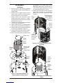
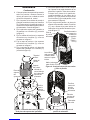
4. Install electronic ignitor through control
panel as shown in Figure 4. Screw retainer
ring and ignitor cap on from outside panel.
Attach ignitor ground wire to ignitor.
Washers
Ignitor Grounding Wire

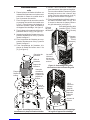
www.desatech.com 118992-01F6
5. Remove wire tie and packing material
from regulator located underneath burner
support plate.
6. Position burner support plate on top of
panels while carefully inserting control
valve through hole in control panel.
7. Attach control valve bracket to table
control panel with 2 screws (C). Attach
control knob to control valve from outside
of heater. See Figure 5.
8. Attach burner support plate to panels with
4 screws (C) (see Figure 5).
9.
Attach emitter screens to emitter brackets
with 4 screws (C) as shown in the Figure 5.
10. Attach emitter cap to emitter brackets with
2 screws (C) as shown in Figure 5.
11. Attach emitter assembly to burner support
plate with 2 screws (C) (see Figure 5).
12. Model TD109 only: Place 3 screens around
ASSEMBLY
Continued
Burner
Support
Plate
Figure 7 - Attaching Grate Assembly to
Heater
Screw
through
Deco
Grate
Pillar
Figure 6 - Deco Grate and Grate Pillar
Assembly
grate pillars. For all models, place 3 table
decorative grate pieces around grate pil-
lars. Attach to grate pillars with 4 screws
(C) per grate as shown in Figure 6.
13.
Attach grate assembly to burner support
plate using 3 screws, (C) one through
bottom of each deco grate pillar (see
Figure 7).
Burner
Support
Plate
Hole for
Control
Valve
Control
Knob
Figure 5 - Assembling Emitter and
Attaching Burner Support Plate
Emitter Cap
Emitter
Screen
Emitter
Bracket
Control Valve
Underneath
Burner
Support Plate
Ring
Retainer
Screen
(Model
TD109
only)
Table Decorative
Grate (Models
TD101, TD103
and TD111
shown)
Deco
Grate
Pillar
(Holes
closest to
edge should
be on the
bottom)

www.desatech.com
118992-01F 7
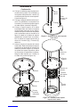
Deflector
Figure 8 - Deector Assembly
Deflector
Bracket
Deco
Grate
Pillar
14. Place one deflector over deco grate
pillars. Attach deflector and brackets to
pillars with 1 screw (C) through each of
the 3 brackets. See Figure 8.
15. Place second deflector over rst deflector.
Attach deflector to brackets with 2 screws
(C) through the top of each bracket (see
Figure 8).
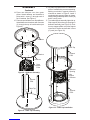
Figure 9 - Table Top Assembly
Support
Pillar
Table Top
ASSEMBLY
Continued
16. Lay table top upside down on a blanket or
piece of cardboard to prevent scratching.
Making sure holes in support pillars are
oriented as shown in Figure 9, install 3
remaining table support pillars as shown.
Attach pillars to table top with 2 screws (D)
and 2 nuts (E) each.
17. Turn table support assembly right side up.
Slide support pillars through openings in
deflector assembly (see Figure 10). Posi-
tion top support pillars over pillar support
connectors. Secure each set with 1 screw
(C) each (see Figure 10).
Figure 10 - Table Top Installation
Table Top
Deflector
Opening
Support
Pillar
Support
Pillar
Pillar
Support
Connector

www.desatech.com 118992-01F8
ASSEMBLY
Continued
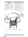
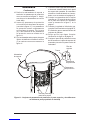
18. Slide support brackets over guard rails as
shown in Figure 11. Make certain brackets
curve downward.
19. Insert guard rails into holes of support
pillars (see Figure 11). Guard rails will go
completely through support pillars. Attach
nut (G) to ends of guard rails as shown in
Figure 11.
20. Attach support brackets to bottom deflec-
tor using 2 screws (F) each as shown in
Figure 11.
Figure 11 - Guard Rail Assembly (top and deectors cut away for clarity)
Guard
Rail
Slots for
Hanging
Door Panel
21. Connect black ignitor wire and electrode
located underneath burner support plate
to electronic ignitor. Install battery in
ignitor as shown on page 14.
22. Place ring retainers ("S" hooks) through
holes in burner support place as shown
in Figure 7, page 6.
23. Connect regulator to gas cylinder, see
Operation, page 9. Gas cylinder will set
inside of cabinet assembly.
24. Check for leaks. See Checking for Leaks
page 9.
25. Hang table door panel from slots in burner
support plate to cover inside of heater.
Support
Pillar
Nut
Guard
Rail
Support
Bracket

www.desatech.com
118992-01F 9
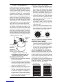
LIGHTING INSTRUCTIONS
1. Push heater control knob in and turn coun-
ter clockwise to the START position.
2. Push knob in and press IGNITOR button.
Repeat until heater is lit.
3. Continue holding knob in for approxi-
mately 30 seconds. Heater should remain
lit in the LOW heat setting.
4. For more heat, press knob and rotate
counterclockwise to HIGH setting.
5. If RELIGHTING, wait 5 minutes for heater
to cool and gas to clear, then follow steps
1 through 3.
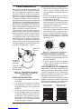
Figure 14 - Burner Operation
IGNITOR
OFF
START-LOW
HIGH
Figure 13 - Heater Controls
SHUTDOWN INSTRUCTIONS
1. Press control knob and rotate clockwise
to OFF position.
2. Close propane/LP cylinder valve (rotate
knob clockwise).
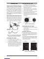
BURNER OPERATION
Visually inspect burner for proper operation.
A correct burner pattern shows blue flames
with some yellow tipping and top half of emit-
ter glows red.
An incorrect burner pattern shows large
flames more than half the height of emitter
coming outside of emitter. Flame should stay
contained inside emitter.
Correct
Burner Pattern
Incorrect
Burner Pattern
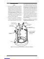
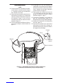
Figure 12 - Connecting Hose/Regulator
Assembly to Propane/LP Cylinder
OPERATION
Use only a 20 lb. propane/LP cylinder (not
included). See safety information for proper
cylinder selection. Connect hose/regulator
assembly to propane cylinder (see Figure
12). Hose should already be connected to
heater. When connecting regulator assembly
to cylinder valve, hand tighten nut clockwise
to a positive stop. DO NOT use a wrench to
tighten. Use of a wrench may damage quick
closing coupling nuts and result in a hazard-
ous condition.
Route retention chain through at least one
handle of propane/LP tank (see Figure 12).
Make sure to route chain through handle on
tank and NOT around tank valve. Chain must
not interfere with valve. Attach hooks on both
ends of chains to ring retainers installed on
burner support plate. See Figure 7, page 6.
CHECKING FOR LEAKS
1. Turn heater valve to OFF position.
2. Turn cylinder supply valve fully counter
clockwise to OPEN position.
3. Use a noncorrosive leak detection solution
to check the connection. For leaks before
attempting to light heater. If leak is found,
turn cylinder valve to CLOSE and do not
use until all leaks are corrected.
20 lb.
Propane/LP
Cylinder
Hose/Regulator
Assembly
Retention
Chain

www.desatech.com 118992-01F10
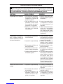
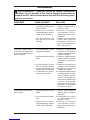
SYMPTOM
Burner fails to light
Burner lights but goes out
when automatic control valve
button is released
Maximum burn rate is low
TROUBLESHOOTING
WARNING: Never attempt to service heater while it is connected
to propane/LP supply, operating, or hot. Severe burns can occur.
POSSIBLE CAUSE
1. Propane/LP supply valve
closed on propane/LP cyl-
inder
2. Blockage in burner/orice
elbow/hose and regulator
assembly
3. Battery not installed, battery
power low or battery not
installed correctly
1. Not enough warm up time
2. Low gas pressure
3. Thermocouple loose or
needs to be replaced
4. Automatic control valve
needs to be replaced
5. Thermocouple gap is too
great
1. Low gas pressure
2. Low fuel supply
3. Restriction in burner/orice
elbow/hose and regulator
assembly
REMEDY
1. Open propane/LP supply
valve slowly
2. Clean burner/replace orice
elbow/hose and regulator
assembly
3. Install new alkaline battery
in electronic ignitor. Verify
battery is installed correctly.
See page 14
1. Relight, hold automatic
control valve button in 30
seconds
2. Check propane/LP cylinder
for proper gas supply
3. Tighten connection or re-
place thermocouple
4. Replace automatic control
valve assembly
5. Tip of thermocouple should
just touch the emitter mate-
rial. Loosen bracket screws
to move thermocouple clos-
er to burner. Be careful not
to allow ignitor to touch.
Maintain 0.20"
1. Check gas supply; check
regulator output
2. Consult propane/LP gas
supplier
3. Clean burner/replace orice
elbow/hose and regulator
assembly

www.desatech.com
118992-01F 11
SPECIFICATIONS
• Rating: High - 16,000 Btu/Hr (4.69 kw)
Low - 9,500 Btu/Hr (2.78 kw)
• Fuel: Propane Vapor Only
• Fuel Consumption/Hour: Min. 0.10 gal (0.39 liter), Max. 0.17 gal (0.66 liter)
Min. 0.44 lb (0.20 kg), Max 0.74 lb (0.33 kg)
• Supply Pressure (To Regulator): Maximum - 200 psi (1,379 Kpa)
Minimum, for input adjustment - 5 psi (34.5 Kpa)
• Manifold Pressure: High - 11 WC (2.74 kPa), Low - 10.6 psi (73.08 kPa)
• Ignitor Gap: 0.120"
• Minimum Temperature: -20°F (29°C) Surrounding Air Temperature
• Heater Size (L x W x H): 30.5" x 30.5" x 43.5" (0.77 x 0.77 x 1.1 m)
• Carton Size (L x W x H): 25.75" x 25.75" x 16.25" (0.65 x 0.65 x 0.41 m)
• Heater Weight: 73 lb (33.1 kg)
• Shipping Weight: 84 lb (38.1 kg)
STORAGE
CAUTION: Disconnect heater
from propane/LP supply cylinder.
1. Do not store heater while attached to
propane/LP cylinder. Close cylinder valve.
Remove the hose/regulator assembly
from the propane/LP cylinder by turning
the fuel gas connector nut clockwise.
2. Storage of heater inside is permissible
only if the cylinder is disconnected and
removed from the appliance.
3. Store propane/LP cylinder in safe manner.
Refer to Chapter 5 of Standard for Storage
and Handling of Liqueed Petroleum Gases,
ANSI/NFPA 58. Follow all local codes.
Cylinders must be stored outdoors in a
well-ventilated area out of reach of children.
Disconnected cylinders must have threaded
valve plugs tightly installed, and must not be
stored in a building, garage or any other en-
closed area. Never store cylinders near high
heat, open flame, or where temperatures
exceed 100° F (38° C).
4. Store in a dry, clean, and safe place.
MAINTENANCE
WARNING: Never attempt to
service heater while it is con-
nected to propane/LP supply,
operating, or hot. Severe burns
can occur. Any guard or other
protective device removed for
servicing must be replaced prior
to operating the heater.
1. Keep heater clean. Remove any debris
from ventilation openings.
2. Inspect heater before each use. Check
connections for leaks. Apply mixture of
liquid soap and water to connections.
Bubbles forming show a leak that must
be corrected. Correct all leaks at once.
3. Inspect hose/regulator assembly before
each use. If hose is highly worn or cut,
replace it immediately. At least annually,
remove hose/regulator assembly from
heater to inspect entire length of hose.
4. Spiders and insects can create a danger-
ous condition that may damage heater or
make it unsafe. Keep burner area clean
of all spiders, webs, or insects.
5. Have heater inspected yearly by a quali-
ed service person.


www.desatech.com
118992-01F 13
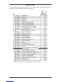
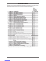
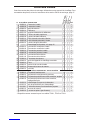
PARTS LIST
This list contains replaceable parts used in your heater. When ordering parts, follow the
instructions listed under Replacement Parts, page 15.
KEY
NO. PART NO. DESCRIPTION QTY.
1 118858-01 Table Top • 1
118858-02 Table Top • • 1
2 118866-01 Guard Rail • • • 3
3 118856-01 Deflector • • • 2
4 118871-01 Deflector Spacer Bracket • • • 3
5 118850-01 Upper Table Support Pillar • • • 3
6 118850-02 Lower Table Support Pillar • • • 3
7 118855-01 Table Decorative Grate, Mission • • 3
118855-02 Table Decorative Grate, Ornate • 3
8 118854-01 Deco Grate Pillar • • • 3
9––––– Emitter Assembly, see page 14 • • • 1
10 118859-01 Table Control Panel • 1
118859-02 Table Control Panel • • 1
11 118860-01 Table Door Panel • 1
118860-02 Table Door Panel • • 1
12 118851-01 Lower Table Panel • 1
118851-02 Lower Table Panel • • 1
13 119309-01 Pillar Support Connector • • • 3
14 118848-01 Table Heater Base • • • 1
15 118849-01 Wheel • • • 2
16 118862-01 Table Wheel Axle • • • 2
17 119625-01 Guard Rail Support Bracket • • • 3
18 119940-01 Screen • 3
PARTS AVAILABLE - NOT SHOWN
118988-01 Warning Decal • • • 1
118989-01 General Information Decal • • • 1
118990-05 Control Position Decal, English • • • 1
118990-03 Control Position Decal, Spanish/French • • • 1
119102-01 Regulator and Hose Assembly • • • 1
119103-01 Assembly Hardware Bag • • • 1
119110-01 Propane Tank Retention Chain • • • 1
118863-01 Ring Retainer • • • 2
119422-01 Accessory Cover* • 1
TD101, TD111
TD103
TD109
* Available as accessory for models TD101, TD103 and TD111.

www.desatech.com 118992-01F14
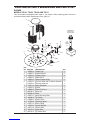
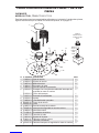
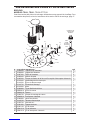
ILLUSTRATED PARTS BREAKDOWN AND PARTS LIST
BURNER
MODELS TD101, TD103, TD109 AND TD111
This list contains replaceable parts used in your heater. When ordering parts, follow the
instructions listed under Replacement Parts, page 15.
KEY
NO. PART NO. DESCRIPTION QTY.
1 119282-01 Emitter Cap 1
2 119280-01 Emitter Bracket 2
3 118870-01 Emitter Screen 2
4 118864-01 Table Burner 1
5 118852-01 Burner Support Plate 1
6 119104-01 Thermocouple with Tip Switch Harness 1
119105-01 Thermocouple Nut 1
7 119107-01 Ignitor Electrode 1
8 119106-01 Injector 1
9 118869-01 Burner Flex Line 1
10 098508-01 Valve Nut 1
11 099393-03 Knob 1
12 118867-01 Valve Mounting Plate 1
13 108498-01 Tip Switch 1
14 118868-01 Control Valve 1
15 111435-01 Electronic Ignitor 1
16 119557-01 Elbow Fitting 1
17 119610-01 Injector Bracket 1
18 119611-01 Ground Wire 1
19 120413-01 Ignitor Wire 1
20 120412-01 Tip Switch Wire 2
1
2
3
4
6
8
17
9
10
11
12
13
14
15
20
18
7
5
19
16
Install Battery
According To
This Illustration
AA
Battery
Positive
UP

www.desatech.com
118992-01F 15
REPLACEMENT PARTS
WARNING: Use only original
replacement parts. This heater
mustusedesign-specicparts.
Do not substitute or use generic
parts. Improper replacement
parts could cause serious or fa-
tal injuries. This will also protect
your warranty coverage for parts
replaced under warranty.
PARTS UNDER WARRANTY
Contact authorized dealers of this product. If
they can’t supply original replacement part(s),
either contact your nearest Parts Central or
call DESA Heating Products’ Technical Ser-
vice Department at 1-866-672-6040.
When calling DESA Heating Products, have
ready
• your name
• your address
• model and serial numbers of your heater
• purchase date
• how heater was malfunctioning
In most cases, we will ask you to return the
part to the factory.
PARTS NOT UNDER WARRANTY
Contact authorized dealers of this product. If
they can’t supply original replacement part(s),
either contact your nearest Parts Central listed
in the Authorized Service Center booklet
supplied with heater or call DESA Heating
Products (US) at 1-866-672-6040 or DESA
Industries (CAN) at 1-416-255-5333 for refer-
ral information.
When calling DESA Heating Products, have
ready
• model number of your heater
• the replacement part number
TECHNICAL SERVICE
You may have further questions about instal-
lation, operation, or troubleshooting. If so,
contact DESA Heating Products’ Technical
Service Department at 1-866-672-6040.
When calling please have your model and
serial numbers of your heater ready.
You can also visit DESA Heating Products’ tech-
nical service web site at www.desatech.com.
ACCESSORY
Purchase accessories and parts from your
nearest dealer or service center. If your dealer
or service center can not supply an accessory
or part, either contact your nearest Parts
Central (listed in the separate Authorized
Service Center booklet) or call DESA Heating
Products (US) at 1-866-672-6040 or DESA In-
dustries (CAN) at 1-416-255-5333 for referral
information. You can also write to the address
listed on the back page of this manual.
PATIO HEATER COVER - 119422-01
A heater cover accessory may be purchased
to protect your patio heater. Made of black
polyester material with Outdoor Leisure
logo.
Patio heater cover accessory may be ordered
through this website:
www.aboutoutdoorleisure.com
Click “Online Outlet”.
Click “Patio Heaters”.
Click “Accessories”.

2701 Industrial Drive
P.O. Box 90004
Bowling Green, KY 42102-9004
www.desatech.com
This warranty does not cover discoloration due to operation of heater. We reserve the right to amend these
specifications at any time without notice. The only warranty applicable is our standard written warranty. We
make no other warranty, expressed or implied.
WARRANTY SERVICE
Should your heater require service, return it to your nearest authorized service center. Proof of purchase
must be presented with the heater. The heater will be inspected. A defect may be caused by faulty materials
or workmanship. If so, DESA Heating Products will repair or replace the heater without charge.
REPAIR SERVICE
Return the heater to your nearest authorized service center. Each Service Center is independently owned
and operated. Repairs not covered by the warranty will be billed at standard prices. We reserve the right
to amend these specifications at any time without notice.
For information about this warranty write:
WARRANTY INFORMATION
LIMITED WARRANTY
DESA Heating Products warrants this product and any parts thereof, to be free from defects in materials
and workmanship for one (1) year for residential home owner usage or 90 days for commercial/industrial
usage from the date of rst purchase when operated and maintained in accordance with instructions.
This warranty is extended only to the original retail purchaser, when proof of purchase is provided.
This warranty covers only the cost of parts and labor required to restore the product to proper operating
condition. Transportation and incidental costs associated with warranty repairs are not reimbursable
under this warranty.
Warranty service is available only through authorized dealers and service centers.
This warranty does not cover defects resulting from misuse, abuse, negligence, accidents, lack of proper
maintenance, normal wear, alteration, modication, tampering, contaminated fuels, repair using improper
parts, or repair by anyone other than an authorized dealer or service center. Routine maintenance is
the responsibility of the owner.
THIS EXPRESS WARRANTY IS GIVEN IN LIEU OF ANY OTHER WARRANTY EITHER EXPRESSED
OR IMPLIED, INCLUDING WARRANTIES OF MERCHANTABILITY AND FITNESS FOR A PARTICU-
LAR PURPOSE.
DESA Heating Products assumes no responsibility for indirect, incidental or consequential damages.
Some states do not allow the exclusion or limitation of incidental or consequential damages or limita-
tions or exclusions may not apply to you. This Limited Warranty gives you specic legal rights and you
may also have other rights which vary from state to state.
82 Akron Road
Toronto, Ontario
M8W 1T2
www.desatech.com
118992-01
Rev. F
09/06

CALENTADOR INFRARROJO DE
PROPANO O GAS LP PARA PATIO
TIPO MESA BISTRO
MANUAL DEL PROPIETARIO
MODELOS
TD101, TD103,
TD109 Y TD111
Configuración ajustable
de la temperatura:
Baja 9,500 BTU
Alta 16,000 BTU
Para obtener más información, visite www.desatech.com
ADVERTENCIA:
para uso en exte-
riores solamente
POR SU SEGURIDAD
Si percibe olor a gas:
1. Cierre el suministro de gas al aparato.
2.
Apague cualquier llama al descubierto.
3. Si el olor continúa, llame inmediata-
mente a su proveedor de gas.
Llénelo para sus expedientes
N° de modelo ______________
(Situado en el panel lateral)
N° de serie _________________
(Situado en el panel lateral)
Fecha de compra ____________
ADVERTENCIA: lea y comprenda este manual antes de
ensamblar, arrancar o dar servicio al calentador. El uso in-
adecuado del calentador puede ocasionar lesiones graves,
daños a la propiedad o la muerte. Conserve este manual
para referencias futuras.
INSTALADOR: deje este manual junto con el aparato.
CONSUMIDOR: conserve este manual para futuras referencias.
POR SU SEGURIDAD
No guarde ni utilice gasolina u otros vapores y líquidos
inamables cerca de este aparato ni de cualquier otro.

www.desatech.com 118992-01F2
INFORMACIÓN DE
SEGURIDAD
ADVERTENCIA: este produc-
to contiene y/o genera químicos
reconocidos por el estado de
California como causantes de
cáncer, defectos de nacimiento
u otros daños reproductivos.
ADVERTENCIA: peligro de
incendio, quemaduras, inhala-
ción y explosión. Mantenga los
combustibles sólidos, como
materiales de construcción,
madera, revestimientos de vinilo,
papel o cartón a una distancia
segura del calentador, como se
recomienda en las instruccio-
nes. Nunca use el calentador en
espacios que contengan o que
pudieran contener combustibles
volátiles o suspendidos en el
aire, ni productos como gasolina,
solventes, disolvente de pintura,
partículas de polvo o productos
químicos desconocidos.
ADVERTENCIA: si la instala-
ción, el ajuste, las alteraciones,
el servicio o el mantenimiento no
se realizan correctamente, se po-
drían ocasionar lesiones, daños
a la propiedad o la muerte. Lea
cuidadosamente las instruccio-
nes de instalación, operación y
mantenimiento antes de instalar
el equipo o realizar tareas de
mantenimiento.
ADVERTENCIA: para usarse
en exteriores solamente, en un
área bien ventilada. No utilice el
calentador en interiores ni en un
edicio, garaje o cualquier otra
área cerrada o sin ventilación.
Este calentador está diseñado para usarse como
un calentador infrarrojo para patios, de acuerdo con
los requisitos aplicables de CSA 5.90 Calentado-
res infrarrojos para patio en EE.UU. y CAN 1-2.23
Calentadores infrarrojos portátiles para Canadá.
Otros estándares rigen el uso de gases combus-
tibles y productos para calefacción para usos
informarle acerca de éstos. El objetivo principal
de los calentadores para patios en exteriores es
proporcionar calefacción a espacios residencia-
les y no residenciales. Cuando se usa correcta-
mente, este calentador proporciona calefacción
económica y segura.
No podemos prever todos los usos que se les
pueden dar a nuestros calentadores. CON-
SULTE A LAS AUTORIDADES LOCALES
DE SEGURIDAD CONTRA INCENDIOS SI
TIENE ALGUNA PREGUNTA ACERCA DEL
USO DE CALENTADORES.
Intoxicación con monóxido de carbono: El
monóxido de carbono afecta más a unas
de intoxicación con monóxido de carbono
son semejantes a los de la gripe, con dolor de
cabeza, mareo o náusea. Si usted presenta
estos síntomas, es posible que el calentador
no esté funcionando correctamente. ¡Respire
aire fresco inmediatamente! Haga que le den
servicio al calentador.
Propano o gas LP:
agente que tiene olor. El olor le ayuda detectar
desvanecer. Es posible que haya propano o gas
advertencias. Conserve este manual como
referencia. Es su guía para la operación segura
y correcta de este calentador.
TABLA DE CONTENIDO
Información de seguridad .................................... 2
................................... 5
Desempaque ....................................................... 5
Ensamble............................................................. 5
Funcionamiento ................................................. 10
Solución de problemas .......................................11
Almacenamiento ................................................ 12
Mantenimiento ................................................... 12
................................................ 13
...14
............................................ 17
Servicio técnico ................................................. 17
Accesorios ......................................................... 17
Información de garantía..................................... 18

www.desatech.com
118992-01F 3
Todas las protecciones u
otros dispositivos de segu-
ridad que se hayan retirado
para dar servicio al calentador
se deberán volver a colocar antes
de operarlo.
La temperatura de las supercies
puede llegar a ser muy alta cuan-
do el calentador está funcionan-
do. Los niños y los adultos deben
permanecer lejos del calentador
para evitar quemaduras o que la
ropa se encienda.
Se debe supervisar a los niños
pequeños cuidadosamente
cuando estén en el área donde
se encuentra el calentador.
No se debe colgar ropa ni otros
materiales inflamables en el
calentador, ni se deben colocar
cerca del mismo.
La instalación y las reparaciones
deben ser realizadas por una perso-
na de servicio calicada. El calen-
tador debe ser inspeccionado por
una persona de servicio calicada
antes de usarse y por lo menos
una vez al año. Es posible que se
requiera limpiarlo más frecuente-
mente, según sea necesario. Es
imprescindible mantener limpios
los compartimientos, los quemado-
res y los conductos de circulación
de aire del calentador.
PRECAUCIÓN: se debe usar
el regulador de presión de gas
incluido con este aparato. Este
regulador está congurado para
una presión de salida de 27.9 cm
(11") de C.A. (0.4 PSI).
INFORMACIÓN DE
SEGURIDAD Continuación
Figura 1 - Distancia mínima del
calentador hacia objetos combustibles
1. Instale y use el calentador con cuidado.
Siga todas las ordenanzas y los códigos
locales. A falta de ordenanzas y códigos
Estándar para el alma-
cenamiento y el manejo de gases licuados
de petróleo, ANSI/NFPA 58, código de
instalación CAN/-B149. Éste proporciona
instrucciones acerca del almacenamiento
para extracción de vapores en un cilindro de
9 kg (20 lb). El cilindro debe estar fabricado y
-
partamento de transporte de EE.UU. (DOT).
El cilindro debe contar con una válvula de
cierre con terminación en forma de salida
de la válvula del cilindro de suministro de
roscas externas, debe estar etiquetada
como “Utilizar con tipo 1” y debe contar con
un dispositivo de descarga que tenga comu-
nicación directa con el espacio de vapor del
cilindro. El cilindro debe incluir un anillo para
proteger la válvula del cilindro.
3.
Mantenga el área en dónde se localiza el
aparato despejada y libre de materiales com-
bustibles, gasolina, disolventes para pintura
polvo es combustible. No use el calentador
en áreas con alto contenido de polvo.
4. El derramamiento de líquidos combustibles
en la llama podría ocasionar un incendio.
5. No coloque manteles combustibles sobre
la mesa que sostiene al calentador. Si se
utiliza un mantel, no permita que ninguna
parte del mismo cuelgue sobre el borde de
la mesa hacia el área de salida del calor.
0.91 m (36")
15.2 cm
(6")
15.2 cm
(6")
15.2 cm
(6")
15.2 cm
(6")

www.desatech.com 118992-01F4
INFORMACIÓN DE
SEGURIDAD Continuación
del aparato.
7. Distancia mínima entre el calentador y las
construcciones combustibles permanen-
tes: parte anterior, parte trasera y laterales
15.2 cm (6"), parte superior 0.91 m (36")
-
tador tiene alguna fuga. Nunca use una
llama al descubierto para revisar si hay
alguna fuga. Aplique una mezcla de jabón
formación de burbujas indicará una fuga.
Repare todas las fugas inmediatamente.
a menos de 38 °C (100 °F).
10. Use sólo la manguera y el regulador
preinstalados en la fábrica que se in-
cluyen con el calentador. No ajuste el
regulador, ya que se podrían producir
fugas de gas.
11. Coloque la manguera correctamente,
manteniéndola fuera de zonas en las que
las personas se puedan tropezar con ella
o en áreas en las que la manguera podría
dañarse accidentalmente. Mantenga la
manguera lejos del quemador que se
encuentra en el interior del calentador.
12. Revise la manguera antes de cada uso
del calentador. Desconecte la manguera
con una llave de 9/16". Revise si hay ras-
gaduras o abrasiones en la manguera o
en el regulador. Si la manguera está muy
desgastada o con roturas, reemplácela
fabricante antes de usar el calentador.
13. No altere el calentador. Mantenga el
calentador en su estado original. No use
el calentador si éste ha sido alterado.
estable y nivelada.
15. No opere el calentador mientras duerme
ni lo deje desatendido.
16. Nunca mueva, maneje o dé servicio a un
calentador caliente o en funcionamiento.
esperar 20 minutos después de apagar
el calentador.
manipule el calentador.
18. Cierre la válvula y el suministro de gas al
calentador cuando no lo esté utilizando.
19. Use sólo piezas de repuesto originales.
Este calentador debe usar piezas diseña-
use piezas genéricas. El uso de piezas de
repuesto inadecuadas puede ocasionar
lesiones graves o fatales.
20. Ciertos materiales o artículos, si se al-
macenan frente al calentador, estarán
sujetos a la radiación de calor y podrían
sufrir daños graves.
21. Apague el calentador inmediatamente si
se produce un retorno de la llama (una
llama dentro del tubo del quemador).
Haga que le den servicio al calentador.
22. Nunca intente utilizar el calentador ni nin-
haya sido expuesto a fuego accidental.
23. Si percibe olor a gas o sospecha que hay
una fuga, cierre la válvula del cilindro de
-
le el área. No encienda fósforos, no inicie
fuegos ni produzca chispas eléctricas.
encender cualquier aparato.
24.
No bloquee las aberturas de entrada
de aire.
correctas; consulte la página 13.
incluye. Use un cilindro de 9 kg (20 lb)
etiquetado con la palabra "propano". El
sistema de suministro del cilindro debe
ser adecuado para la extracción de va-
pores. El cilindro debe incluir un anillo
para proteger la válvula del cilindro. El
cilindro debe contar con una válvula de
cierre con terminación en forma de salida
de la válvula del cilindro de suministro de
sea aplicable, par la conexión N° 510 en
el Estándar para conexiones de entrada
y de la boca de salida de la válvula de
cilindros de gas comprimido , ANSI/CGA-
Conexión estándar limitada de la boca
de salida de la válvula del cilindro para
la serie de propano con válvula pequeña
de la Asociación de gas comprimido, o
una combinación de válvula de cilindro
de desconexión rápida que cumpla con
1.16.5-c y un dispositivo de descarga de
seguridad que tenga comunicación direc-
ta con el espacio de vapor del cilindro.
La page est en cours de chargement...
La page est en cours de chargement...
La page est en cours de chargement...
La page est en cours de chargement...
La page est en cours de chargement...
La page est en cours de chargement...
La page est en cours de chargement...
La page est en cours de chargement...
La page est en cours de chargement...
La page est en cours de chargement...
La page est en cours de chargement...
La page est en cours de chargement...
La page est en cours de chargement...
La page est en cours de chargement...
La page est en cours de chargement...
La page est en cours de chargement...
La page est en cours de chargement...
La page est en cours de chargement...
La page est en cours de chargement...
La page est en cours de chargement...
La page est en cours de chargement...
La page est en cours de chargement...
La page est en cours de chargement...
La page est en cours de chargement...
La page est en cours de chargement...
La page est en cours de chargement...
La page est en cours de chargement...
La page est en cours de chargement...
La page est en cours de chargement...
La page est en cours de chargement...
La page est en cours de chargement...
La page est en cours de chargement...
-
 1
1
-
 2
2
-
 3
3
-
 4
4
-
 5
5
-
 6
6
-
 7
7
-
 8
8
-
 9
9
-
 10
10
-
 11
11
-
 12
12
-
 13
13
-
 14
14
-
 15
15
-
 16
16
-
 17
17
-
 18
18
-
 19
19
-
 20
20
-
 21
21
-
 22
22
-
 23
23
-
 24
24
-
 25
25
-
 26
26
-
 27
27
-
 28
28
-
 29
29
-
 30
30
-
 31
31
-
 32
32
-
 33
33
-
 34
34
-
 35
35
-
 36
36
-
 37
37
-
 38
38
-
 39
39
-
 40
40
-
 41
41
-
 42
42
-
 43
43
-
 44
44
-
 45
45
-
 46
46
-
 47
47
-
 48
48
-
 49
49
-
 50
50
-
 51
51
-
 52
52


Outdoor Leisure td101 Le manuel du propriétaire
- Taper
- Le manuel du propriétaire
dans d''autres langues
Documents connexes
Autres documents
-
Desa Td101, Td103, Td109, Td111 Manuel utilisateur
-
-
-
-
-
-
-