
Bluetooth 5.1 Dual Mode Transceiver Module Based on CC2564C
info@bdecomm.com
BDE Technology Inc.
Datasheet
BDE-BD2564CN
1 / 14
General Description
BD2564CN is a Bluetooth 5.1 BR/EDR & LE dual mode transceiver module.
The module integrates Bluetooth classic and Bluetooth Low Energy radio TI’s CC2564C, a
26-MHz crystal oscillator, a band pass filter and all the passive components at a very
affordable cost.
The module provides the best-in-class RF performance with transmit power and receive
sensitivity that provides twice the range and higher throughput than other Bluetooth-
low-energy-only solutions. The power-management hardware and software algorithms
provide significant power savings in all commonly used Bluetooth BR/EDR and low energy
modes of operation.
The certified and royalty free Dual-mode Bluetooth 4.2 protocol stack software provides a complete Bluetooth BR/EDR,
and Bluetooth Low Energy sample applications that reduce design effort and ensure a faster time to market.
The module has a very small form factor with the dimensions of 7 mm x 7 mm x 1.55 mm.
Key Features
Bluetooth 5.1 dual mode
Bluetooth Basic Rate (BR)
Enhanced Data Rate (EDR)
Low Energy (LE)
BR and EDR features include:
Up to seven active devices
Scatternet: Up to three piconets simultaneously,
one as master and two as slaves
Up to two Synchronous Connection Oriented
(SCO) links on the same piconet
Support for all voice air-coding – continuously
Variable Slope Delta (CVSD), A-Law, μ-Law,
modified Subband Coding (mSBC), and
transparent (Uncoded)
Provide an assisted mode for HFP 1.6 Wideband
Speech (WBS) profile or A2DP profile to reduce
host processing and power
Support of multiple Bluetooth profiles with
enhanced QoS
Low Energy features include:
Multiple sniff instances tightly coupled to
achieve minimum power consumption
Independent buffering for Low Energy allows
large numbers of multiple connections without
affecting BR or EDR performance
Built-In coexistence and prioritization handling
for BR, EDR, and Low Energy
Capabilities of link layer topology, Scatternet -
can act concurrently as peripheral and central
Network support for up to 10 devices
Time line optimization algorithms to achieve
maximum channel utilization
Best-in-Class Bluetooth (RF) performance (TX power,
RX sensitivity, blocking)
Class 1 TX power up to +12 dBm
Internal temperature detection and
compensation to ensure minimal variation in RF
performance over temperature, no external
calibration required
Improved Adaptive Frequency Hopping (AFH)
Algorithm with minimum adaptation time
Longer range, including twice the range of
other Low-Energy-Only solutions
Advanced power management for extended battery
life and ease of design
On-Chip power management, including direct
connection to battery
Low power consumption for active, standby,

Bluetooth 5.1 Dual Mode Transceiver Module Based on CC2564C
info@bdecomm.com
BDE Technology Inc.
Datasheet
BDE-BD2564CN
2 / 14
and scan Bluetooth modes
Shutdown and sleep modes to minimize powe
consumption
Physical interfaces:
UART Interface with support for maximum
Bluetooth data rates
UART transport layer (H4) with maximum rate
of 4 Mbps
Three-Wire UART transport layer (H5) with
maximum rate of 4 Mbps
Fully programmable Digital Pulse-Code
Modulation (PCM) - I2S codec interface
Flexibility for easy stack integration and validation
into MCUs and MPUs
HCI tester tool to evaluate RF performance of the
device and configure service pack
Antenna: without antenna
Size: 7 mm x 7 mm x 1.55 mm (With Shield)
Standards Conformance
Bluetooth® SIG
CE-RED (Europe)
FCC (US)
ISED (Canada)
Japan (Telec)

Bluetooth 5.1 Dual Mode Transceiver Module Based on CC2564C
info@bdecomm.com
BDE Technology Inc.
Datasheet
BDE-BD2564CN
3 / 14
Applications
Mobile Accessories
Sports and Fitness Applications
Wireless Audio Solutions
Set-Top Boxes and Remote Controls
Toys
Test and Measurement
Industrial: Cable Replacement
Wireless Sensors
Automotive Aftermarket
Wellness and Health

Bluetooth 5.1 Dual Mode Transceiver Module Based on CC2564C
info@bdecomm.com
BDE Technology Inc.
Datasheet
BDE-BD2564CN
4 / 14
Contents
General Description .............................................................................................................................................................. 1
Key Features .......................................................................................................................................................................... 1
Applications .......................................................................................................................................................................... 3
Contents ................................................................................................................................................................................ 4
1. Block Diagram ............................................................................................................................................................... 5
2. Pinout ........................................................................................................................................................................... 6
3. Characteristics .............................................................................................................................................................. 7
3.1. Absolute Maximum Ratings ............................................................................................................................. 7
3.2. Recommended Operating Conditions .............................................................................................................. 8
4. Mechanical Specifications ............................................................................................................................................ 9
4.1. Dimensions ...................................................................................................................................................... 9
4.2. PCB Footprint ................................................................................................................................................. 10
5. Marking ...................................................................................................................................................................... 10
6. Ordering Information ................................................................................................................................................. 11
7. Regulation ................................................................................................................................................................... 11
7.1. FCC Warning ................................................................................................................................................... 11
7.2. FCC Statements .............................................................................................................................................. 12
7.3. Module statement ......................................................................................................................................... 12
7.4. IC Statements ................................................................................................................................................. 13
8. Revision History .......................................................................................................................................................... 14
Contacts .............................................................................................................................................................................. 14

Bluetooth 5.1 Dual Mode Transceiver Module Based on CC2564C
info@bdecomm.com
BDE Technology Inc.
Datasheet
BDE-BD2564CN
5 / 14
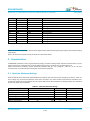
1. Block Diagram
BD2564CN integrates Bluetooth classic and Bluetooth Low Energy radio TI’s CC2564C, a 26-MHz crystal oscillator, a band
pass filter and all the passive components at a very affordable cost.
Figure 1-1 shows the block diagram of the module.
Figure 1-1. The block diagram of BD2564CN (Confidential)

Bluetooth 5.1 Dual Mode Transceiver Module Based on CC2564C
info@bdecomm.com
BDE Technology Inc.
Datasheet
BDE-BD2564CN
6 / 14
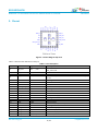
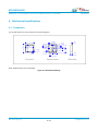
2. Pinout
19 AUD_IN
20 AUD_OUT
21 AUD_CLK
22 AUD_FSYNC
23 NC
24 TX_DBG
GND
NC
GND
HCI_RTS
HCI_RX
HCI_TX
HCI_CTS
GND
31
6
5
4
3
2
1
30
VDD_IN 12
NC 11
NC 10
GND 9
SLOW_CLK_IN 8
GND 7
32
13
14
15
16
17
18
33
GND
GND
BT_ANT
GND
nSHUTD
GND
VDD_IO
GND
25
GND
26
GND
29
GND
27
GND
28
GND
Bottom View
Figure 2-1. Pinout Diagram Top View
Table 2-1 describes the definitions of the pins.
Table 2-1. Pin Description
Pin #
Pin Name
Type
Description
1
HCI_CTS
DI(Note 1), PU(Note 2)
HCI UART clear-to-send. The device can send data when
HCI_CTS is low
2
HCI_TX
DO, PU
HCI UART data transmit
3
HCI_RX
DI, PU
HCI UART data receive
4
HCI_RTS
DO, PU
HCI UART request-to-send. Host can send data when HCI_RTS
is low
5
GND
GND
Power ground
6
NC
-
Not connected
7
GND
DIO
GPIO, Sensor Controller
8
SLOW_CLK_IN
DI
32.768-kHz clock in, fail-safe
9
GND
GND
Power ground
10
NC
-
Not connected
11
NC
-
Not connected
12
VDD_IN
Power
Main power supply for the module (2.2 to 4.8 V)
13
GND
GND
Power ground
14
BT_ANT
AIO
Bluetooth RF I/O
15
GND
GND
Power ground
16
nSHUTD
DI, PD
Shutdown input (active low)
17
GND
GND
Power ground
18
VDD_IO
Power
I/O power supply (1.8 V nominal)
19
AUD_IN
DI, PD
PCM data input, fail-safe
20
AUD_OUT
DO, PD
PCM data onput, fail-safe
21
AUD_CLK
DIO(Note 1), PD
PCM clock, fail-safe

Bluetooth 5.1 Dual Mode Transceiver Module Based on CC2564C
info@bdecomm.com
BDE Technology Inc.
Datasheet
BDE-BD2564CN
7 / 14
Pin #
Pin Name
Type
Description
22
AUD_FSYNC
DIO, PD
PCM frame sync, fail-safe
23
NC
-
Not connected
24
TX_DBG
DO, PU
Internal debug messages
25
GND
GND
Power ground
26
GND
GND
Power ground
27
GND
GND
Power ground
28
GND
GND
Power ground
29
GND
GND
Power ground
30
GND
GND
Power ground
31
GND
GND
Power ground
32
GND
GND
Power ground
33
GND
GND
Power ground
Note 1: DI stands for Digital Input, DO stands for Digital Output, DIO stands for Digital Input-Output, AIO stands for Analog
Input Ouput;
Note 2: PU stands for internal Pull-Up, PD stands for internal Pull-Down.
3. Characteristics
All MIN/MAX specification limits are guaranteed by design, production testing and/or statistical characterization. Typical
values are based on characterization results at default measurement conditions and are informative only.
Default measurement conditions (unless otherwise specified): VDD_IN = 3.6 V, VDD_IO = 1.8V, TA = 25 ℃. All radio
measurements are performed with standard RF measurement equipment.
3.1. Absolute Maximum Ratings
Stresses beyond those listed under Absolute Maximum Ratings may cause permanent damage to the device. These are
stress ratings only, so functional operation of the device at these or any other conditions beyond those indicated in the
operational sections of the specification are not implied. Exposure to Absolute Maximum Rating conditions for extended
periods may affect device reliability.
Table 3-1. Absolute Maximum Ratings
PARAMETER
MIN
MAX
UNIT
Notes
VDD_IN
-0.5
4.8
V
VDD_IO
-0.5
2.415
V
Input voltage to analog pin
-0.5
2.1
V
BT_ANT
Input voltage to all other pins
-0.5
VDD_IO + 0.5
Bluetooth RF pin
8
dBm
Storage Temperature
-40
100
°C

Bluetooth 5.1 Dual Mode Transceiver Module Based on CC2564C
info@bdecomm.com
BDE Technology Inc.
Datasheet
BDE-BD2564CN
8 / 14
3.2. Recommended Operating Conditions
Table 3-2. Recommended Operating Conditions
PARAMETER
MIN
TYP
MAX
UNIT
VDD_IN
2.2
4.8
V
VDD_IO
1.62
1.92
V
Operating Temperature
-40
-
85
°C

Bluetooth 5.1 Dual Mode Transceiver Module Based on CC2564C
info@bdecomm.com
BDE Technology Inc.
Datasheet
BDE-BD2564CN
9 / 14
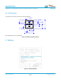
4. Mechanical Specifications
4.1. Dimensions
The module dimensions are presented in the following figure:
6.2
6.2
0.4
2 x (0.4)
20 x (0.9)
28 x (0.5)
4 x (0.8)
4 x (0.8)
5 x (1) 5 x (1)
4 x (1.6)
28 x (0.5)
3.5
3.5
1.55
Top View Bottom View Side View
7
7
0.6
Note: All dimensions are in millimeter
Figure 4-1. Mechanical Drawing

Bluetooth 5.1 Dual Mode Transceiver Module Based on CC2564C
info@bdecomm.com
BDE Technology Inc.
Datasheet
BDE-BD2564CN
10 / 14
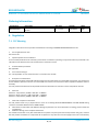
4.2. PCB Footprint
The footprint for the PCB is presented in the following figure:
28 x (0.5)
20 x (0.9)
4 x (1.6)
4 x (0.8)
5 x (1)
28 x (0.5) 5 x (1)
3.5
3.5
Via
7
7
4 x (0.8)
Note: All dimensions are in millimeter
Figure 4-2. Module Footprint Top View
5. Marking
Figure 5-1. Module Marking

Bluetooth 5.1 Dual Mode Transceiver Module Based on CC2564C
info@bdecomm.com
BDE Technology Inc.
Datasheet
BDE-BD2564CN
11 / 14
Ordering Information
Part Number
Description
Size (mm)
Package
MOQ
BDE-BD2564CN
Bluetooth 5.1 Dual Mode Transceiver
Module
7 × 7 × 1.55
Tape & Reel
1000
6. Regulation
7.1. FCC Warning
Integration instructions for host product manufacturers according to KDB 996369 D03 OEM Manual v01
1. List of applicable FCC rules
FCC Part 15.247
2. Specific operational use conditions
This transmitter/module and its antenna(s) must not be co-located or operating in conjunction with any transmitter. This
information also extends to the host manufacturer’s instruction manual.
3. Limited module procedures
Not applicable
4. Trace antenna designs
It is “not applicable” as trace antenna which is not used on the module.
5. RF exposure considerations
This equipment complies with FCC RF radiation exposure limits set forth for an uncontrolled environment. This compliance
to FCC radiation exposure limits for an uncontrolled environment, and minimum of 20cm separation between antenna
and body.
The host product manufacturer would provide the above information to end users in their end-product manuals.
6. Antennas
Antenna 1: Chip antenna; 0.5dBi; 2.402 GHz ~ 2.480GHz
Antenna 2: Whip antenna; 2.5dBi; 2.402 GHz ~ 2.480GHz
Antenna 3: Chip antenna; 0.8dBi; 2.402 GHz ~ 2.480GHz
7. Label and compliance information
The end product must carry a physical label or shall use e-labeling followed KDB784748D01 and KDB 784748 stating
“Contains Transmitter Module FCC ID: 2ABRU-2564C”.
8. Information on test modes and additional testing requirements. For more information on testing, please contact the
manufacturer.
9. Additional testing, Part 15 Subpart B disclaimer
The modular transmitter is only FCC authorized for the specific rule parts (FCC Part 15.247) listed on the grant, and that
the host product manufacturer is responsible for compliance to any other FCC rules that apply to the host not covered by

Bluetooth 5.1 Dual Mode Transceiver Module Based on CC2564C
info@bdecomm.com
BDE Technology Inc.
Datasheet
BDE-BD2564CN
12 / 14
the modular transmitter grant of certification. The final host product still requires Part 15 Subpart B compliance testing
with the modular transmitter installed when contains digital circuity.
7.2. FCC Statements
(OEM) Integrator has to assure compliance of the entire end-product incl. the integrated RF Module. For 15 B (§15.107
and if applicable §15.109) compliance, the host manufacturer is required to show compliance with 15 while the module
is installed and operating.
Furthermore the module should be transmitting and the evaluation should confirm that the module's intentional
emissions (15C) are compliant (fundamental / out-of-band). Finally the integrator has to apply the appropriate equipment
authorization (e.g. Verification) for the new host device per definition in §15.101.
Integrator is reminded to assure that these installation instructions will not be made available to the end-user of the final
host device.
The final host device, into which this RF Module is integrated" has to be labeled with an auxiliary label stating the FCC ID
of the RF Module, such as "Contains FCC ID: 2ABRU-2564C
"This device complies with part 15 of the FCC rules. Operation is subject to the following two conditions:
(1) this device may not cause harmful interference, and
(2) this device must accept any interference received, including interference that may cause undesired operation."
"Changes or modifications to this unit not expressly approved by the party responsible for compliance could void the
user’s authority to operate the equipment."
The Integrator will be responsible to satisfy SAR/ RF Exposure requirements, when the module integrated into the host
device.
7.3. Module statement
The single-modular transmitter is a self-contained, physically delineated, component for which compliance can be
demonstrated independent of the host operating conditions, and which complies with all eight requirements of §
15.212(a)(1) as summarized below.
(1) The radio elements have the radio frequency circuitry shielded.
(2) The module has buffered modulation/data inputs to ensure that the device will complywith Part 15 requirements with
any type of input signal.
(3) The module contains power supply regulation on the module.
(4) The module contains a permanently attached antenna.
(5) The module demonstrates compliance in a stand-alone configuration.

Bluetooth 5.1 Dual Mode Transceiver Module Based on CC2564C
info@bdecomm.com
BDE Technology Inc.
Datasheet
BDE-BD2564CN
13 / 14
(6) The module is labeled with its permanently affixed FCC ID label.
(7) The module complies with all specific rules applicable to the transmitter, including all the conditions provided in the
integration instructions by the grantee.
(8) The module complies with RF exposure requirements.
NOTE: This equipment has been tested and found to comply with the limits for a Class B digital device, pursuant to part
15 of the FCC Rules. These limits are designed to provide reasonable protection against harmful interference in a
residential installation. This equipment generates uses and can radiate radio frequency energy and, if not installed and
used in accordance with the instructions, may cause harmful interference to radio communications. However, there is no
guarantee that interference will not occur in a particular installation. If this equipment does cause harmful interference
to radio or television reception, which can be determined by turning the equipment off and on, the user is encouraged to
try to correct the interference by one or more of the following measures:
- Reorient or relocate the receiving antenna.
- Increase the separation between the equipment and receiver.
-Connect the equipment into an outlet on a circuit different from that to which the receiver is connected.
-Consult the dealer or an experienced radio/TV technician for help
7.4. IC Statements
The final host device, into which this RF Module is integrated" has to be labeled with an auxiliary label stating the IC of
the RF Module, such as" Contains transmitter module IC: 25657-2564C
Le périphériquehôte final, danslequelce module RF estintégré "doitêtreétiqueté avec uneétiquetteauxiliaireindiquant le
CI du module RF, tel que" Contient le module émetteur IC: 25657-2564C
This device contains licence-exempt transmitter(s)/receiver(s) that comply with Innovation, Science and Economic
Development Canada’s licence-exempt RSS(s). Operation is subject to the following two conditions:
(1) This device may not cause interference.
(2) This device must accept any interference, including interference that may cause undesired operation of the device.
L’émetteur/récepteur exempt de licencecontenudans le présentappareilestconforme aux CNR d’Innovation, Sciences et
Développementéconomique Canada applicables aux appareils radio exempts de licence. L’exploitationestautorisée aux
deux conditions suivantes :
(1) L' appareil ne doit pas produire de brouillage;
(2) L' appareildoit accepter tout brouillageradioélectriquesubi, mêmesi le brouillageest susceptible d' encompromettre le
fonctionnement.
RF Exposure Warning Statements:
This equipment complies with FCC radiation exposure limits set forth for an uncontrolled environment.
This equipment shall be installed and operated with minimum distance 20cm between the radiator & body.

Bluetooth 5.1 Dual Mode Transceiver Module Based on CC2564C
info@bdecomm.com
BDE Technology Inc.
Datasheet
BDE-BD2564CN
14 / 14
Radio Frequency Exposure Statement for IC:
The device has been evaluated to meet general RF exposure requirements. The device can be used in mobile exposure
conditions. The min separation distance is 20cm.
Déclaration d'exposition aux radiofréquences pour IC:
L'appareil a été évalué pour répondre aux exigences générales en matière d'exposition aux RF. L'appareil peut être utilisé
dans des conditions d'exposition mobiles. La distance de séparation minimale est de 20 cm.
This radio transmitter [IC: 25657-2564C] has been approved by Innovation, Science and Economic Development Canada
to operate with the antenna types listed below, with the maximum permissible gain indicated. Antenna types not included
in this list that have a gain greater than the maximum gain indicated for any type listed are strictly prohibited for use with
this device.
Cet émetteur radio [IC: 25657-2564C] a été approuvé par Innovation, Sciences et Développement économique Canada
pour fonctionner avec les types d'antenne énumérés ci-dessous, avec le gain maximal admissible indiqué. Les types
d'antenne non inclus dans cette liste qui ont un gain supérieur au gain maximum indiqué pour tout type répertorié sont
strictement interdits pour une utilisation avec cet appareil.
7. Revision History
Revision
Date
Description
V1.0
17-July-2021
Initial Release, brief
V1.1
22-November-2021
Update some data, replace picture
Contacts
Guangzhou BDE Technology Inc.
USA: 67 E Madison St, # 1603A, Chicago, IL 60603, US
Tel: +1-312-379-9589
Website: http://www.bdecomm.com Email: [email protected]om
China: B2-403, ChuangYi Building, 162 Science Avenue, Huangpu District, Guangzhou 510663, China
Tel: +86-20-28065335
Website: http://www.bdecomm.com Email: [email protected]
-
 1
1
-
 2
2
-
 3
3
-
 4
4
-
 5
5
-
 6
6
-
 7
7
-
 8
8
-
 9
9
-
 10
10
-
 11
11
-
 12
12
-
 13
13
-
 14
14


BDE BD2564CN Bluetooth 5.1 Dual Mode Transceiver Module Based on CC2564C Manuel utilisateur
- Taper
- Manuel utilisateur
- Ce manuel convient également à
dans d''autres langues
Autres documents
-
ZHIRONG WLT3266 Manuel utilisateur
-
A D PAPZ7128 Manuel utilisateur
-
VESTEL 17BT02 Bluetooth module Manuel utilisateur
-
Shenzhen Liangming Technology LM80P2-0001AA Wireless Module Manuel utilisateur
-
Sengled MX1290 Manuel utilisateur
-
Carrier 10105567G1 Manuel utilisateur
-
HP HSN-L01NFM Manuel utilisateur
-
MICROCHIP WLR089U0 Regulatory Compliance Manuel utilisateur
-
 Yokogawa Electric F9092LD ISA100 Wireless Module Manuel utilisateur
-
 HON HAI PRECISION IND. MCLJ20H077 Manuel utilisateur

