Peerless PC930A-S Guide d'installation
- Catégorie
- Supports de plafond à panneau plat
- Taper
- Guide d'installation

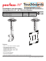
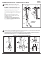
Installation and Assembly:
Ceiling Mount for 15" - 40" Flat Panel Displays
Features:
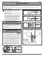
• VESA® 75 / 100 / 200x100 / 200x200 compatible
• Three adjustable extension lengths:
PC930A/PC932A models - 9.8" - 13.9"
PC930B/ PC932B models - 13.78" - 21.89"
PC930C/ PC932C models - 20.24" - 34.02"
• Adjustable tilt of +20/-5°
• 360° of mountable adjustment
• Internal cable management
• Safety catch designed into extension channels to ensure user and equipment safety
ISSUED: 11-29-07 SHEET #: 202-9263-3 04-25-14
2300 White Oak Circle • Aurora, Il 60502 • (800) 865-2112 • Fax: (800) 359-6500 • www.peerlessmounts.com
Models Screen Size Range Max UL Load Capacity
PC930A, PC930A-S, PC930A-W, PC930B, PC930B-S, PC930B-W,
PC930C, PC930C-S, PC930C-W 15" to 24" 50 lb (22.7 kg)
PC932A, PC932A-S, PC932A-W, PC932B, PC932B-S, PC932B-W,
PC932C, PC932C-S, PC932C-W 15" to 40" 80 lb (36.3 kg)
Modelos Gama de tamaño de
las pantallas
Capacidad de carga
máxima de UL
PC930A, PC930A-S, PC930A-W, PC930B, PC930B-S, PC930B-W,
PC930C, PC930C-S, PC930C-W de 15" a 24" 50 lb (22.7 kg)
PC932A, PC932A-S, PC932A-W, PC932B, PC932B-S, PC932B-W,
PC932C, PC932C-S, PC932C-W de 15" a 40" 80 lb (36.3 kg)
Modèles Plage de dimensions
de l’écran
Capacité de charge
maximale établie par l’UL
PC930A, PC930A-S, PC930A-W, PC930B, PC930B-S, PC930B-W,
PC930C, PC930C-S, PC930C-W 15 à 24 po 50 lb (22.7 kg)
PC932A, PC932A-S, PC932A-W, PC932B, PC932B-S, PC932B-W,
PC932C, PC932C-S, PC932C-W 15 à 40 po 80 lb (36.3 kg)
PC930 Series PC932 Series

2 of 35 ISSUED: 11-29-07 SHEET #: 202-9263-3 04-25-14
Note: Read entire instruction sheet before you start installation and assembly.
Table of Contents
Parts List............................................................................................................................................................................ 3, 4
Install Outer Channel to Ceiling Plate.....................................................................................................................................4
Installation to Wood Joist ........................................................................................................................................................5
Installation to Concrete Ceilings .............................................................................................................................................6
Installing Inner Channel and Routing Cables .........................................................................................................................7
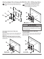
Attaching Mounting Plate to Display with VESA 75 or 100 Mounting Pattern ........................................................................8
Attaching Adapter Plate to Display with VESA 200 x 100 or 200 x 200 Mounting Pattern .....................................................9
Installing Flat Panel Display ............................................................................................................................................... 10
Adjusting Mount Extension .................................................................................................................................................. 10
Adjusting Display ..................................................................................................................................................................11
Install Cable Covers .............................................................................................................................................................11
Tools Needed for Assembly
• studnder("edgetoedge"studnderisrecommended)
• drill
• level
• 5/16" bit for concrete
• 5/32" bit for wood joist
• phillips screwdriver
• Do not begin to install your Peerless product until you have read and understood the instructions and warnings
contained in this Installation Sheet. If you have any questions regarding any of the instructions or warnings, for US
customers please call Peerless customer care at 1-800-865-2112, for all international customers, please contact
your local distributor.
• This product should only be installed by someone of good mechanical aptitude, has experience with basic building
construction, and fully understands these instructions.
• Make sure that the supporting surface will safely support the combined load of the equipment and all attached
hardware and components.
• Never exceed the Maximum UL Load Capacity. See page one.
• If mounting to wood ceiling studs, make sure that mounting screws are anchored into the center of the studs. Use
ofan"edgetoedge"studnderishighlyrecommended.
• Always use an assistant or mechanical lifting equipment to safely lift and position equipment.
• Tightenscrewsrmly,butdonotovertighten.Overtighteningcandamagetheitems,greatlyreducingtheirholding
power.
• This product is intended for indoor use only. Use of this product outdoors could lead to product failure and personal
injury.
• This product was designed to be installed on the following ceiling construction only;
CEILING CONSTRUCTION HARDWARE REQUIRED
• Wood Stud, Joist Included
• Wood Beam Included
• Solid Concrete Included
WARNING

3 of 35 ISSUED: 11-29-07 SHEET #: 202-9263-3 04-25-14
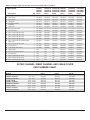
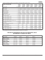
OUTER CHANNEL, INNER CHANNEL AND CABLE COVER
PART NUMBER CHART
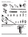
Before you begin, make sure all parts shown are included with your product.
Parts may appear slightly different than illustrated.
Parts List PC930A,
PC930B,
PC930C
Part #
PC930A-S
PC930B-S
PC930C-S
Part #
PC930A-W,
PC930B-W,
PC930C-W
Part #
PC932A,
PC932B,
PC932C
Part #
PC932A-S,
PC932B-S,
PC932C-S
Part #
PC932A-W,
PC932B-W,
PC932C-W
Part #Description Qty
Aceiling plate 1 096-1292 096-4292 096-2292 096-1292 096-4292 096-2292
Bouter channel 1 See Chart See Chart See Chart See Chart See Chart See Chart
Cinner channel 1 See Chart See Chart See Chart See Chart See Chart See Chart
Dclamp plate 1 055-1771 055-4771 055-2771 055-1771 055-4771 055-2771
Eswivel/pivot bracket 1 055-1811 055-4811 055-2811 055-1811 055-4811 055-2811
Ftilt bracket 1 095-1484 095-4484 095-2484 095-1484 095-4484 095-2484
Gcable cover 2 See Chart See Chart See Chart See Chart See Chart See Chart
H#14 x 2.5 wood screw 2 5S1-015-C03 5S1-015-C04 5S1-015-C04 5S1-015-C03 5S1-015-C04 5S1-015-C04
Iconcrete anchor 2 590-0320 590-0320 590-0320 590-0320 590-0320 590-0320
JM5 x 10 mm socket pin screw 8 520-1063 520-2063 520-2063 520-1063 520-2063 520-2063
KM6 x 10 mm socket pin screw 4 520-1066 520-2066 520-2066 520-1066 520-2066 520-2066
LM6 x 12 mm socket pin screw 2 520-1050 520-2050 520-2050 520-1050 520-2050 520-2050
MM4 x 10 mm socket pin screw 4 520-1060 520-2060 520-2060 520-1060 520-2060 520-2060
NM4 x 12 mm socket pin serrated washer
head screw
4 510-1079 510-2079 510-2079 510-1079 510-2079 510-2079
OM4 x 20 mm socket pin screw 4 520-1061 520-2163 520-2163 520-1061 520-2163 520-2163
Pretaining spacer 4 590-5005 590-5005 590-5005 590-5005 590-5005 590-5005
Q4 MM security allen wrench 1 560-9646 560-9646 560-9646 560-9646 560-9646 560-9646
Radaptor plate 1 N/A N/A N/A 095-1721 095-4721 095-2721
SM5 x 6 mm socket pin screw 4 N/A N/A N/A 520-1114 520-2062 520-2062
T#10atwasher 4 N/A N/A N/A 540-9400 540-9442 540-9442
UM6 x 12 mm socket pin screw 4 N/A N/A N/A 520-1050 520-2050 520-2050
VM6 x 20 mm socket pin screw 4 N/A N/A N/A 520-9554 520-2554 520-2554
WM8 x 10 mm socket pin screw 4 N/A N/A N/A 520-1706 520-2706 520-2706
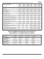
Model #
extendable length outer channel (B)
part #
inner channel (C)
part #
cable cover (G)
part #
PC930A, PC932A 9.8" - 13.9" 055-1779 055-1778 055-1809-2
PC930A-S, PC932A-S 9.8" - 13.9" 055-4779 055-4778 055-4809-2
PC930A-W, PC932A-W 9.8" - 13.9" 055-2779 055-2778 055-2809-2
PC930B, 9C932B 13.78" - 21.89" 055-1776 055-1775 055-1809-1
PC930B-S, PC932B-S 13.78" - 21.89" 055-4776 055-4775 055-4809-1
PC930B-W, PC932B-W 13.78" - 21.89" 055-2776 055-2775 055-2809-1
PC930C, PC932C 20.24" - 34.02" 055-1770 055-1769 055-1809
PC930C-S, PC932C-S 20.24" - 34.02" 055-4770 055-4769 055-4809
PC930C-W, PC932C-W 20.24" - 34.02" 055-2770 055-2769 055-2809

4 of 35 ISSUED: 11-29-07 SHEET #: 202-9263-3 04-25-14
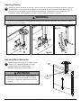
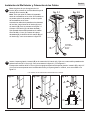
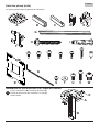
Attach outer channel (B) to ceiling plate (A) using
four M6 x 10 mm socket pin screws (K) as shown.
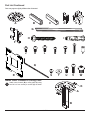
A B C D E
F
G
H I
R
Part List Continued
Parts may appear slightly different than illustrated.
Install Outer Channel to Ceiling Plate
A
B
K
1
S U VT
Q
J K L M N O P
W

5 of 35 ISSUED: 11-29-07 SHEET #: 202-9263-3 04-25-14
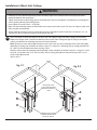
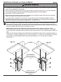
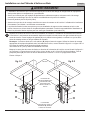
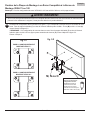
Installation to Wood Joist Ceilings
Useastudndertolocatetheedgesofthejoist.Useofanedge-to-edgestudnderishighlyrecommended.
Based on its edges, draw a vertical line down the joist’s center. Place ceiling plate (A) on ceiling as a template,
making sure that the two mounting slots are on the stud centerline.
Note: Opening on outer channel (B) indicates front of mount. Use the correct mounting slots on the ceiling plate
dependingonceilingjoistorientationasshowningure2.1orgure2.2.Mountingslotsonceilingplateallowfor
45° (±22.5) of swivel adjustment before securing to joist.
Markthecenterofthetwomountingholesdependingonjoistorientationasshowningure2.1orgure2.2.Drill
two 5/32" (4 mm) dia. holes 2-1/2" (65 mm) deep. Secure ceiling plate (A) to wood joist using two #14 x 2-1/2"
wood screws (H) as shown.
Skip to step 3.
• Installer must verify that the supporting surface will safely support the combined load of the equipment and all
attached hardware and components.
• Tightenwoodscrewssothatceilingplateisrmlyattached,butdonotovertighten.Overtighteningcandamagethe
screws, greatly reducing their holding power.
• Never tighten in excess of 80 in. • lb (9 N.M.).
• Make sure that mounting screws are anchored into the center of the stud or joist. The use of an "edge to edge" stud
nderishighlyrecommended.
• When installing Peerless mounts on a wood joist or beam verify that the joists or beams are a minimum of 2" x 4"
nominal size. Do not install over gypsum board thicker than 5/8".
WARNING
OPENING ON OUTER
CHANNEL (B) INDICATES
FRONT OF MOUNT
H
H
B
AA
WOOD
JOIST
g. 2.2
g. 2.1
B
MOUNTING SLOTS
ALLOW FOR ROTATION
BEFORE SECURING TO
JOIST
2

6 of 35 ISSUED: 11-29-07 SHEET #: 202-9263-3 04-25-14
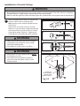
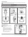
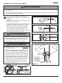
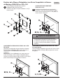
Installation to Concrete Ceilings
• When installing Peerless wall mounts on a concrete ceiling, it must be at least 8" thick with a minimum compressive
strength of 2000 psi. Lighter density concrete may not hold concrete anchor.
• Make sure that the supporting surface will safely support the combined load of the equipment and all attached hard-
• Always attach concrete expansion anchors directly
to load-bearing concrete.
• Never attach concrete expansion anchors to
concrete covered with plaster, drywall, or other
nishingmaterial.
Place ceiling plate (A) on ceiling as a template and
mark the center of the two mounting holes.
Note: Opening in outer channel indicates the front
of the mount.
Drill two 5/16" (8 mm) dia. holes to a minimum
depth of 2.5" (64 mm). Attach ceiling plate (A) using
two concrete anchors (I) and two #14 x 2.5" wood
screws (H)asshowningure2.3.Tightenwood
screws (H) until ceiling plate (A)isrmlyattached.
H
A
I
2
g. 2.3 B
OPENING ON
OUTER CHANNEL
(B) INDICATES
FRONT OF MOUNT
WARNING
• Tightenwoodscrewsrmly,butdonotovertighten.
Overtightening can damage the screws, greatly
reducing their holding power.
• Never tighten in excess of 80 in • lb (9 N.M.)
WARNING
WARNING
1
3
I
Drill holes and insert anchors (I).
Place plate (A) over anchors (I) and secure with screws (H).
Tighten all fasteners.
2
I
A
H
concrete
surface
CONCRETE CEILING

7 of 35 ISSUED: 11-29-07 SHEET #: 202-9263-3 04-25-14
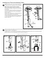
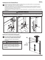
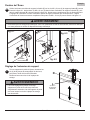
Note: Be certain holes on inner channel (C) face in
the same direction of opening on outer channel (B).
Note: Cables must be removed from display
before routing through channels. If cables are not
removable from display, routing through channels is
not an option.
Guide display cables into openings in channels then
insert inner channel (C) into outer channel (B) as
showningure3.1.
Position inner channel (C) to the desired height and
secure using two M6 x 12 mm socket pin
screws (L) through clamp plate (D), through opening
in outer channel (B) and into inner channel (C) as
showningure3.2.
Insert swivel/pivot bracket (E) into end of inner channel (C) and secure with four M5 x 10 mm socket pin screws (J)
asshowningure4.1andgure4.2.
Thread two M5 x 10 mm screws (J) into top holes of swivel/pivot bracket (E), leaving 1/8" (3 mm) exposed thread
betweenheadofscrewandswivel/pivotbracketasshowningure4.3.
Installing Inner Channel and Routing Cables
OPENING
B
C
HOLES
GUIDE
CABLES IN
CHANNELS
g. 3.1 g. 3.2
LDB
C
CABLES NOT SHOWN FOR CLARITY
g. 4.3
1/8"
(3 mm)
1/8"
(3 mm)
E
J
E
J
g. 4.2
g. 4.1
C
E
C
J
E
FRONT VIEW
3
4

8 of 35 ISSUED: 11-29-07 SHEET #: 202-9263-3 04-25-14
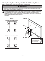
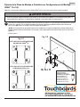
Attaching Mounting Plate to Display with VESA 75 or 100 Mounting Pattern
Chooseholepatternasshowningure5.1whichmatchesholepatternonbackofyourdisplay.Attachtiltbracket
(F) to back of display using four M4 x 10 mm screws (M) or M4 x 12 mm screws (N)asshowningure5.2.
*NOTE: If hole pattern is in a pocket, attach tilt bracket (F) to back of display using four M4 x 20 mm screws (O)
and four retaining spacers (P)asindicatedingure5.2.
Skip to step 6.
M, N or O
F
Note: For VESA 200 x 100 mm and 200 x 200 mm hole patterns, see following page.
FOR VESA 75 MOUNTING PATTERN:
FOR VESA 100 MOUNTING PATTERN:
g. 5.1 g. 5.2
*For displays with a hole
pattern in a pocket, spacers
go between tilt bracket and
display when used with
M4 x 20 mm screws (O). P
5
• If screws don't get three complete turns in the display inserts or if screws bottom out and bracket is still not tightly
secured, damage may occur to display or product may fail.
WARNING

9 of 35 ISSUED: 11-29-07 SHEET #: 202-9263-3 04-25-14
F
R
S
T
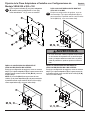
Choose hole pattern as shown below. Attach adapter plate
(R) to back of display using four M4 screws (M or N) as
shown below.
NOTE: If screw (M or N) gets less than three threads of
engagement, attach adapter plate (R) to back of display
using four M4 x 20 mm screws (O) and four spacers (P) as
indicated below.
Choose hole pattern as shown below. Attach adapter plate
(R) to back of display using four M6 or M8 screws (U, V,
W) as shown below.
FOR VESA 200 x 100 MOUNTING PATTERN:
Choose hole pattern as shown below. Attach
adapter plate (R) to back of display using four
M4 screws (M, N, O) as shown below.
Attach tilt bracket (F) onto adapter plate (R) using
four M5 x 6 mm screws (S) and #10 washers (T) as
shown.
5
Attaching Adapter Plate to Display with VESA 200 or 200 x 100 Mounting Pattern
R
R
M, N, O
M, N, O U, V, W
R
• If screws don't get three complete turns in the
display inserts or if screws bottom out and bracket is
still not tightly secured, damage may occur to display
or product may fail.
WARNING
FOR VESA 200 MOUNTING PATTERN USING
M4 SCREWS:
FOR VESA 200 MOUNTING PATTERN USING
M6 OR M8 SCREWS:
5-1

10 of 35 ISSUED: 11-29-07 SHEET #: 202-9263-3 04-25-14
Guide hook slots of tilt bracket (F) onto M5 x 10 mm screws (J) in swivel/pivot bracket (E)asshowningure6.1.
Thread two M5 x 10 mm screws (J) through tilt slot of tilt bracket (F) into swivel/pivot bracket (E) as shown in
gure6.2.Donotfullytightenscrewstoallowfortiltadjustments.Tiltslotallowsforincrementaltiltsof5°.
Adjust tilt of display and fully tighten all four M5 x 10 mm screws (J)asshowningure6.3.
g. 6.1
g. 6.2
g. 6.3
FE
J
HOOK
SLOTS J
EJ
Attaching Display
Adjusting Mount Extension
While supporting the weight of the display, loosen
screws (L) on clamp plate (D) half a turn and
position display to the desired height.
Retighten clamp plate screws securely.
CLAMP PLATE
SCREWS
TILT
SLOTS
F
L
D
6
7
• Clamp plate adjustment screws support weight of
display when fully tightened. Weight of the display
will need to be supported if clamp plate screws are
loosened.
WARNING
• Do not lift more weight than you can handle. Use additional man power or mechanical lifting equipment to safely
handle placement of the display.
WARNING

11 of 35 ISSUED: 11-29-07 SHEET #: 202-9263-3 04-25-14
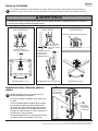
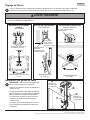
Adjusting Display
© 2011, Peerless Industries, Inc. All rights reserved.
All other brand and product names are trademarks or registered trademarks of their respective owners.
NOTE: Be certain mount is in the desired
extended position.
Attach cables to display if routed through
channels.
Cut cable covers (G) to the length of inner
channel (C) and outer channel (B) openings,
leaving space for cables if routed through
channels. Snap cable covers into openings as
shown.
Cables not routed through channels will
require cable ties (not included).
Install Cable Covers
9
CUT TO
LENGTH OF
OPENING
G
CUT TO
LENGTH OF
OPENING
G
C
If screws indicated are fully tightened, loosen screws half a turn to allow for adjusting tilt, swivel and roll. Adjust
display to the desired position and fully tighten screws.
8
• Do not loosen adjustment screws to the point they become disengaged from the mount. Weight of the display
should be supported in case of accidental disengagement.
SCREWS FOR
ROLL ADJUSTMENT
SCREWS FOR
TILT ADJUSTMENT
(BOTH SIDES)
SCREWS FOR SWIVEL ADJUSTMENT
25° (+20°/-5°) TILT 90° (±45°) SWIVEL6° (±3°) ROLL
ROLL ADJUSTMENT
BACK VIEW
TILT ADJUSTMENT
SIDE VIEW
SWIVEL ADJUSTMENT
BOTTOM VIEW
B
SLOT ALLOWS FOR
INCREMENTAL TILT
ADJUSTMENTS OF 5°
WARNING

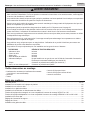
Instalación y ensamblaje:
Soporte de Techo para 15" - 40" Pantallas
Características:
• Compatible con VESA® 75 / 100 / 200 x 100 / 200 x 200
• Tres longitudes de extensión ajustable
PC930A/PC932A modelos - 9.8" - 13.9"
PC930B/ PC932B modelos - 13.78" - 21.89"
PC930C/ PC932C modelos - 20.24" - 34.02"
• Inclinación ajustable de +20/-5°
• 360° de ajuste al instalar
• Manejo de cables interno
• Dispositivo asegurador de diseño integrado a los rieles de extensión para garantizar la seguridad del usuario y del equipo
PUBLICADO: 11-29-07 HOJA #: 202-9263-2 08-17-11
2300 White Oak Circle • Aurora, Il 60502 • (800) 865-2112 • Fax: (800) 359-6500 • www.peerlessmounts.com
Models Screen Size Range Max UL Load Capacity
PC930A, PC930A-S, PC930A-W, PC930B, PC930B-S, PC930B-W,
PC930C, PC930C-S, PC930C-W 15" to 24" 50 lb (22.7 kg)
PC932A, PC932A-S, PC932A-W, PC932B, PC932B-S, PC932B-W,
PC932C, PC932C-S, PC932C-W 15" to 40" 80 lb (36.3 kg)
Modelos Gama de tamaño de
las pantallas
Capacidad de carga
máxima de UL
PC930A, PC930A-S, PC930A-W, PC930B, PC930B-S, PC930B-W,
PC930C, PC930C-S, PC930C-W de 15" a 24" 50 lb (22.7 kg)
PC932A, PC932A-S, PC932A-W, PC932B, PC932B-S, PC932B-W,
PC932C, PC932C-S, PC932C-W de 15" a 40" 80 lb (36.3 kg)
Modèles Plage de dimensions
de l’écran
Capacité de charge
maximale établie par l’UL
PC930A, PC930A-S, PC930A-W, PC930B, PC930B-S, PC930B-W,
PC930C, PC930C-S, PC930C-W 15 à 24 po 50 lb (22.7 kg)
PC932A, PC932A-S, PC932A-W, PC932B, PC932B-S, PC932B-W,
PC932C, PC932C-S, PC932C-W 15 à 40 po 80 lb (36.3 kg)
PC930 Serie PC932 Serie

13 de 35 PUBLICADO: 11-29-07 HOJA #: 202-9263-2 04-25-14
Español
Nota: Lea la hoja de instrucciones completa antes de comenzar la instalación y el ensamblaje.
Tabla de contenido
Lista de piezas............................................................................................................................................................... 14, 15
Instalación del riel exterior en la placa de techo.................................................................................................................. 15
Instalación en vigas de madera ........................................................................................................................................... 16
Instalación en techos de concreto ....................................................................................................................................... 17
Instalación del riel interior y colocación de los cables ......................................................................................................... 18
FijacióndelaplacademontajeapantallasconconguracionesdemontajeVESA® 75 ó 100 ......................................... 19
FijacióndelaplacaadaptadoraapantallasconconguracionesdemontajeVESA® 200 x 100 ó 200 x 200 ................... 20
Instalación de la pantalla plana .......................................................................................................................................... 21
Ajuste de la extensión del soporte....................................................................................................................................... 21
Ajuste de la pantalla ............................................................................................................................................................ 22
Instalación de las cubiertas de los cables ........................................................................................................................... 22
Herramientas necesarias para el
ensamblaje
• localizador de montantes (se recomienda uno de “borde
a borde”)
• taladro
• nivel
• broca de 5/16" para concreto
• broca de 5/32" para vigas de madera
• destornillador phillips
• No comience a instalar el producto hasta haber leído y entendido las instrucciones y las advertencias contenidas
en la Hoja de Instalación. Si tiene alguna pregunta acerca de cualquiera de las instrucciones o las advertencias, por
favor, llame a Servicio al Cliente al 1-800-865-2112.
• Este producto sólo debe ser instalado por una persona que tenga una buena aptitud mecánica, que tenga experiencia
enconstrucciónbásicadeediciosyqueentiendaestasinstruccionesensutotalidad.
• Asegúresedequelasuperciedeapoyosostendrá,conseguridad,lacargacombinadadelequipoytodoslos
jadoresycomponentes.
• Nunca sobrepase la capacidad máxima de soportar carga aceptada por Underwriters Laboratories. Vea la página 12.
• Si va a instalar el producto en un techo con vigas de madera, asegúrese de que los tornillos de montaje estén
anclados en el centro de las vigas. Se recomienda utilizar un localizador de montantes de “borde a borde”.
• Siempre cuente con la ayuda de un asistente o utilice un equipo mecánico de izar para levantar y colocar el equipo
con más seguridad.
• Aprietelostornillosconrmeza,peronoenexceso.Apretarlosenexcesopuededañarlosartículosypuededisminuir
signicativamentesufuerzadejación.
• Este producto está diseñado para uso en interiores solamente. Utilizar este producto en exteriores podría causar
fallas del producto y lesiones a individuos.
• Este producto fue diseñado para ser instalado en paredes con la siguiente construcción solamente:
CONSTRUCCIÓN DE LA PARED ACCESORIOS NECESARIOS
• Montante de madera Incluido
• Viga de madera Incluido
• Concreto macizo Incluido
•Bloquedehormigóndeescorias Comuníqueseconunprofesionalcalicado
• Montante de metal No lo instale excepto con el juego de accesorios de Peerless para
montantes de metal (no evaluados por UL)
•Ladrillo Comuníqueseconunprofesionalcalicado(noevaluadosporUL)
•¿Otrasupercieonoestáseguro? Comuníqueseconunprofesionalcalicado
ADVERTENCIA

14 de 35 PUBLICADO: 11-29-07 HOJA #: 202-9263-2 04-25-14
Español
Lista de piezas PC930A,
PC930B,
PC930C
N.o de pieza
PC930A-S
PC930B-S
PC930C-S
N.o de pieza
PC930A-W,
PC930B-W,
PC930C-W
N.o de pieza
PC93SA,
PC93SB,
PC93SC
N.o de pieza
PC93SA-S,
PC93SB-S,
PC93SC-S
N.o de pieza
PC93SA-W,
PC93SB-W,
PC93SC-W
N.o de pieza
Descripción Cant.
Aplaca de techo 1 096-1292 096-4292 096-2292 096-1292 096-4292 096-2292
Briel exterior 1 Vea la tabla Vea la tabla Vea la tabla Vea la tabla Vea la tabla Vea la tabla
Criel interior 1 Vea la tabla Vea la tabla Vea la tabla Vea la tabla Vea la tabla Vea la tabla
Dplaca abrazadera 1 055-1771 055-4771 055-2771 055-1771 055-4771 055-2771
Esoporte giratorio / rotatorio 1 055-1811 055-4811 055-2811 055-1811 055-4811 055-2811
Fsoporte inclinable 1 095-1484 095-4484 095-2484 095-1484 095-4484 095-2484
Gcubierta para los cables 2 Vea la tabla Vea la tabla Vea la tabla Vea la tabla Vea la tabla Vea la tabla
Htornillo para madera de 14 x 2.5" 2 5S1-015-C03 5S1-015-C04 5S1-015-C04 5S1-015-C03 5S1-015-C04 5S1-015-C04
Ianclaje para concreto 2 590-0320 590-0320 590-0320 590-0320 590-0320 590-0320
Jtornillo pasador de cabeza hueca de M5 x 10 mm 8 520-1063 520-2063 520-2063 520-1063 520-2063 520-2063
Ktornillo pasador de cabeza hueca de M6 x 10 mm 4 520-1066 520-2066 520-2066 520-1066 520-2066 520-2066
Ltornillo pasador de cabeza hueca de M6 x 12 mm 2 520-1050 520-2050 520-2050 520-1050 520-2050 520-2050
Mtornillo pasador de cabeza hueca de M4 x 10 mm 4 520-1060 520-2060 520-2060 520-1060 520-2060 520-2060
Ntornillo pasador de cabeza hueca con arandela
dentada de M4 x 12 mm
4 510-1079 510-2079 510-2079 510-1079 510-2079 510-2079
Otornillo pasador de cabeza hueca de M4 x 20 mm 4 520-1061 520-2163 520-2163 520-1061 520-2163 520-2163
Pespaciador de retención 4 590-5005 590-5005 590-5005 590-5005 590-5005 590-5005
Qllave allen de seguridad de 4 mm 1 560-9646 560-9646 560-9646 560-9646 560-9646 560-9646
Rplaca adaptadora 1 N/A N/A N/A 095-1721 095-4721 095-2721
Stornillo pasador de cabeza hueca de M5 x 6 mm 4 N/A N/A N/A 520-1114 520-2062 520-2062
Tarandela plana N.o 10 4 N/A N/A N/A 540-9400 540-9442 540-9442
Utornillo pasador de cabeza hueca de M6 x 12 mm 4 N/A N/A N/A 520-1050 520-2050 520-2050
Vtornillo pasador de cabeza hueca de M6 x 20 mm 4 N/A N/A N/A 520-9554 520-2554 520-2554
Wtornillo pasador de cabeza hueca de M8 x 10 mm 4 N/A N/A N/A 520-1706 520-2706 520-2706
TABLA DE NÚMEROS DE PIEZA DEL RIEL EXTERIOR, EL
RIEL INTERIOR Y LA CUBIERTA PARA LOS CABLES
Antes de comenzar, asegúrese de que su producto contiene todas las piezas que se muestran.
Las piezas pueden verse un poco distintas a la ilustración.
N.o de modelo
Longitud
alargable
riel exterior (B)
N.o de pieza
riel interior (C)
N.o de pieza
cubierta para los cables (G)
N.o de pieza
PC930A, PC932A 9.8" - 13.9" 055-1779 055-1778 055-1809-2
PC930A-S, PC932A-S 9.8" - 13.9" 055-4779 055-4778 055-4809-2
PC930A-W, PC932A-W 9.8" - 13.9" 055-2779 055-2778 055-2809-2
PC930B, 9C932B 13.78" - 21.89" 055-1776 055-1775 055-1809-1
PC930B-S, PC932B-S 13.78" - 21.89" 055-4776 055-4775 055-4809-1
PC930B-W, PC932B-W 13.78" - 21.89" 055-2776 055-2775 055-2809-1
PC930C, PC932C 20.24" - 34.02" 055-1770 055-1769 055-1809
PC930C-S, PC932C-S 20.24" - 34.02" 055-4770 055-4769 055-4809
PC930C-W, PC932C-W 20.24" - 34.02" 055-2770 055-2769 055-2809

15 de 35 PUBLICADO: 11-29-07 HOJA #: 202-9263-2 04-25-14
Español
Lista de piezas - continuación
Las piezas pueden verse un poco distintas a la ilustración.
Instalación del Riel Exterior a la Placa de Techo
Fije el riel exterior (B) a la placa de techo (A)
usando cuatro tornillos pasadores de cabeza hueca
de M6 x 10 mm (K), como se muestra.
A B C D E
F
G
A
B
K
1
H I
S U VT
Q
J K L M N O P
RW

16 de 35 PUBLICADO: 11-29-07 HOJA #: 202-9263-2 04-25-14
Español
Instalación en Paredes con Vigas de Madera
Utilice un localizador de montantes para localizar los bordes de las vigas. Se recomienda utilizar un localizador
de montantes de “borde a borde”. Tomando los bordes como punto de referencia, trace una línea vertical por el
centro de la viga. Coloque la placa de techo (A) en el techo para utilizarla como plantilla; asegúrese de que las dos
ranuras de montaje estén sobre la línea que trazó por el centro.
Nota: La abertura del riel exterior (B) indica la parte delantera del soporte. Utilice las ranuras de montaje
apropiadasdelaplacadetecho,segúnlaorientacióndelaviga,comosemuestraenlagura2.1oenlagura
2.2. Las ranuras de montaje de la placa de techo permiten una rotación de 45° (±22.5)antesdejarelsoporteala
viga.
Marqueelcentrodelosdosagujerosdemontajesegúnlaorientacióndelaviga,comosemuestraenlagura2.1
oenlagura2.2.Taladredosagujerosde5/32"(4mm)dediámetroy2-1/2"(65mm)deprofundidad.Fijelaplaca
de techo (A) a la viga de madera usando dos tornillos para madera de 14 x 2-1/2" (H), como se muestra.
Pase al paso 3.
2
• Elinstaladortienequeasegurarsedequelasuperciedeapoyosostendrá,conseguridad,lacargacombinadadel
equipoytodoslosjadoresycomponentes.
• Aprietelostornillosdemaderademaneraquelaplacadetechosejermemente,peronoenexceso.Apretarlos
enexcesopuededañarlostornillosypuededisminuirsignicativamentesufuerzadejación.
• Nunca apriete a más de 80 pulg-lb (9 N•m).
• Asegúrese de que los tornillos de montaje estén anclados en el centro del montante o de la viga. Se recomienda
utilizar un localizador de montantes de “borde a borde”.
• Losaccesoriosparalainstalaciónqueseproveensonparajarelsoporteamontantesdemaderaovigasde
madera a través del yeso-cartón o yeso de grosor estándar. Los instaladores son responsables de suministrar los
accesorios necesarios para otros tipos de instalaciones (no evaluados por UL).
ADVERTENCIA
LA ABERTURA DEL RIEL
EXTERIOR (B) INDICA LA
PARTE DELANTERA DEL
SOPORTE
H
H
B
AA
VIGA DE
MADERA g. 2.2
g. 2.1
B
LAS RANURAS DE
MONTAJE PERMITEN LA
ROTACIÓN ANTES DE
FIJAR EL SOPORTE A LA
VIGA

17 de 35 PUBLICADO: 11-29-07 HOJA #: 202-9263-2 04-25-14
Español
Instalación en Techos de Concreto
Coloque la placa de techo (A) contra el techo a
manera de plantilla y marque el centro de los dos
agujeros de montaje.
Nota: La abertura del riel exterior indica la parte
delantera del soporte.
Taladre dos agujeros de 5/16" (8 mm) de diámetro
a una profundidad mínima de 2.5" (64 mm). Fije
la placa de techo (A) utilizando dos anclajes para
concreto (I) y dos tornillos para madera de
14 x 2.5" (H),comosemuestraengura2.3.
Apriete los tornillos para madera (H) hasta que la
placa de techo (A)sejermemente.
2
• El concreto tiene que tener una densidad mínima de 2,000 psi. Es posible que un concreto de menos densidad no
sostenga el anclaje para concreto.
• Asegúresedequelasuperciedeapoyosostendrá,conseguridad,lacargacombinadadelequipoytodoslos
jadoresycomponentes.
ADVERTENCIA
• Aprietelostornillosparamaderaconrmeza,pero
no en exceso. Apretarlos en exceso puede dañar
lostornillosypuededisminuirsignicativamentesu
fuerzadejación.
• Nunca apriete a más de 80 pulg-lb (9 N•m).
ADVERTENCIA
• Siemprejelosanclajesparaconcretodirectamente
en la pared que sostiene la carga.
• Nuncajelosanclajesparaconcretoaunaparedde
concreto recubierta con yeso, tabique de yeso-cartón
u otro material de acabado. Si es inevitable hacer la
instalaciónenunasuperciedeconcretorecubierta
conunasuperciedeacabado(noevaluadospor
UL),lasuperciedeacabadotienequeserescariada,
como se muestra abajo. Asegúrese de que los
anclajes para concreto no se separen del concreto
cuando apriete los tornillos. Si el grosor de la capa
de yeso o tabique de yeso-cartón tiene un grosor
mayor de 5/8", el instalador tiene que suministrar las
jacionesespeciales (no evaluados por UL).
ADVERTENCIA
VISTA EN CORTE
INCORRECTO CORRECTO
concreto
placa
de
pared
placa
de
pared
concreto
yeso / tabique de yeso-cartón
1
3
I
Taladre los agujeros e inserte los anclajes (I).
Coloque la placa (A) sobre los anclajes (H) y fíjela con los tornillos (I).
Aprietetodaslasjaciones.
2
I
A
H
techo de
concreto
H
A
I
g. 2.3
B
LA ABERTURA DEL
RIEL EXTERIOR (B)
INDICA LA PARTE
DELANTERA DEL
SOPORTE
TECHO DE CONCRETO

18 de 35 PUBLICADO: 11-29-07 HOJA #: 202-9263-2 04-25-14
Español
Nota: Asegúrese de que los agujeros del riel
interior (C) se orienten en la misma dirección que la
abertura del riel exterior (B).
Nota: Tiene que quitar los cables de la pantalla
antes de acomodarlos en los rieles. Si los cables no
se pueden quitar de la pantalla, no tiene la opción
de acomodarlos en los rieles.
Acomode los cables de la pantalla en las aberturas
de los rieles, luego inserte el riel interior (C) en el
riel exterior (B),comosemuestraenlagura3.1.
Coloque el riel interior (C) a la altura deseada y
fíjelo pasando dos tornillos pasadores de cabeza
hueca de M6 x 12 mm (L) a través de la placa
abrazadera (D), la abertura del riel exterior (B) y el
riel interior (C),comosemuestraenlagura3.2.
Inserte el soporte giratorio / rotatorio (E) en el extremo del riel interior (C) y fíjelo con cuatro tornillos pasadores de
cabeza hueca de M5 x 10 mm (J),comosemuestraenlagura4.1yenlagura4.2.
Enrosque dos tornillos de M5 x 10 mm (J) en los agujeros superiores del soporte giratorio / rotatorio (E) y deje 1/8"
(3 mm) de la rosca expuesto entre la cabeza del tornillo y el soporte giratorio / rotatorio, como se muestra en la
gura4.3.
g. 4.3
1/8"
(3 mm)
1/8"
(3 mm)
E
J
E
J
Instalación del Riel Interior y Colocación de los Cables
LOS CABLES NO SE MUESTRAN POR RAZONES DE CLARIDAD
g. 4.2
g. 4.1
C
E
C
J
E
VISTA DELANTERA
B
C
g. 3.1 g. 3.2
LDB
C
ACOMODE
LOS CABLES
EN LOS
RIELES
ABERTURA
AGUJEROS
3
4

19 de 35 PUBLICADO: 11-29-07 HOJA #: 202-9263-2 04-25-14
Español
Fijación de la Placa de Montaje a Pantallas con Conguraciones de Montaje
VESA® 75 ó 100
Seleccionelaconguracióndeagujeros,comosemuestraenlagura5.1,queseaigualalosagujerosdelaparte
trasera de la pantalla. Fije el soporte inclinable (F) a la parte trasera de la pantalla usando cuatro tornillos de
M4 x 10 mm (M) o M4 x 12 mm (N),comosemuestraenlagura5.2.
*NOTA: Silaconguracióndeagujerosestáenunacavidad,jeelsoporteinclinable(F) a la parte trasera de la
pantalla usando cuatro tornillos de M4 x 20 mm (O) y cuatro espaciadores de retención (P), como se indica en la
gura5.2.
Pase al paso 6.
5
Nota: EnelcasodelasconguracionesdemontajeVESA® 200 x 100 y 200 x 200, pase a la próxima página.
EN EL CASO DE LA CONFIGURACIÓN
DE MONTAJE VESA® 75:
EN EL CASO DE LA CONFIGURACIÓN
DE MONTAJE VESA® 100:
g. 5.1
M, N o O
F
g. 5.2
*En el caso de las
pantallas que tienen la
conguración de agujeros
en una cavidad, los
espaciadores van entre
el soporte inclinable y la
pantalla cuando use los
tornillos M4 x 20 mm (O). P
• Si no se les da tres vueltas completas a los tornillos en los insertos de la pantalla o si los tornillos topan fondo y el
soportetodavíanoestárme,sepodríadañarlapantallaoelproductopodríanofuncionarbien.
ADVERTENCIA

20 de 35 PUBLICADO: 11-29-07 HOJA #: 202-9263-2 04-25-14
Español
PARA LAS CONFIGURACION DE MONTAJE
VESA 200 X 100 MM:
Escojaunaconguracióndeagujeros,comose
muestra abajo. Fije la placa adaptadora (R) a la
parte trasera de la pantalla usando cuatro tornillos
de M4 (M, N, O), como se muestra abajo.
Fijación de la Placa Adaptadora a Pantallas con Conguraciones de
Montaje VESA 200 ó 200 x 100
Fije el soporte inclinable (F) a la placa adaptadora
(R) usando cuatro tornillos de M5 x 6 mm (S) y
cuatro arandelas N.o 10 (T), como se muestra.
5
• Si no se les da tres vueltas completas a los tornillos
en los insertos de la pantalla o si los tornillos topan
fondoyelsoportetodavíanoestárme,sepodría
dañar la pantalla o el producto podría no funcionar
bien.
ADVERTENCIA
Escojaunaconguracióndeagujeros,comosemuestra
abajo. Fije la placa adaptadora (R) a la parte trasera de la
pantalla usando cuatro tornillos de M4 (M o N), como se
muestra abajo.
NOTA: Si el tornillo (M o N) enrosca menos de tres
vueltas,jelaplacaadaptadora(R) a la parte trasera de
la pantalla usando cuatro tornillos de M4 x 20 mm (O) y
cuatro espaciadores (P), como se indica abajo.
Escojaunaconguracióndeagujeros,comosemuestra
abajo. Fije la placa adaptadora (R) a la parte trasera de
la pantalla usando cuatro tornillos de M6 o M8 (U, V, W),
como se muestra abajo.
PARA LAS CONFIGURACION DE MONTAJE
VESA 200 MM USANDO M4 SCREWS:
PARA LAS CONFIGURACION DE MONTAJE
VESA 200 MM USANDO M6 O M8 SCREWS:
5-1
F
R
S
T
M, N, O
R
R
R
M, N, O
U, V, W
La page charge ...
La page charge ...
La page charge ...
La page charge ...
La page charge ...
La page charge ...
La page charge ...
La page charge ...
La page charge ...
La page charge ...
La page charge ...
La page charge ...
La page charge ...
La page charge ...
La page charge ...
-
 1
1
-
 2
2
-
 3
3
-
 4
4
-
 5
5
-
 6
6
-
 7
7
-
 8
8
-
 9
9
-
 10
10
-
 11
11
-
 12
12
-
 13
13
-
 14
14
-
 15
15
-
 16
16
-
 17
17
-
 18
18
-
 19
19
-
 20
20
-
 21
21
-
 22
22
-
 23
23
-
 24
24
-
 25
25
-
 26
26
-
 27
27
-
 28
28
-
 29
29
-
 30
30
-
 31
31
-
 32
32
-
 33
33
-
 34
34
-
 35
35


Peerless PC930A-S Guide d'installation
- Catégorie
- Supports de plafond à panneau plat
- Taper
- Guide d'installation
dans d''autres langues
Documents connexes
-
Peerless PC932A-W Manuel utilisateur
-
Peerless ALU0608 Le manuel du propriétaire
-
PEERLESS-AV AEC0203-S Manuel utilisateur
-
Peerless Industries PRG-UNV Manuel utilisateur
-
-
-
-
-
PEERLESS-AV SmartMount ST632 spécification