ESAB HandyPlasma 35i Manuel utilisateur
- Catégorie
- Système de soudage
- Taper
- Manuel utilisateur
Ce manuel convient également à

HandyPlasma 35i
HandyPlasma 45i
OPERATING MANUAL
05/2020 - Revision: AA Manual No.: 0-5584
HandyPlasma 35i
HandyPlasma 45i
0559160135
0559160145

Be sure this information reaches the operator.
You can get extra copies through your supplier.
CAUTION
These INSTRUCTIONS are for experienced operators. If you are not fully familiar
with the principles of operation and safe practices for arc welding and cutting
equipment, we urge you to read our booklet, “Precautions and Safe Practices for
Arc Welding, Cutting, and Gouging,” Booklet 0-5407. Do NOT permit untrained
persons to install, operate, or maintain this equipment. Do NOT attempt to install
or operate this equipment until you have read and fully understand these instruc-
tions. If you do not fully understand these instructions, contact your supplier for
further information. Be sure to read the Safety Precautions before installing or
operating this equipment.
USER RESPONSIBILITY
This equipment will perform in conformity with the description thereof contained in this manual and accompanying la-
bels and/or inserts when installed, operated, maintained and repaired in accordance with the instructions provided. This
equipment must be checked periodically. Malfunctioning or poorly maintained equipment should not be used. Parts that
are broken, missing, worn, distorted or contaminated should be replaced immediately. Should such repair or replace-
ment become necessary, the manufacturer recommends that a telephone or written request for service advice be made
to the Authorized Distributor from whom it was purchased.
This equipment or any of its parts should not be altered without the prior written approval of the manufacturer. The user
of this equipment shall have the sole responsibility for any malfunction which results from improper use, faulty mainte-
nance, damage, improper repair or alteration by anyone other than the manufacturer or a service facility designated by
the manufacturer.
!
How To Use This Manual.
PROTECT YOURSELF AND OTHERS!

ASSUREZ-VOUS QUE CE DOCUMENT D’INFORMATION EST DISTRIBUÉ À L’OPÉRATEUR.
DES COPIES SUPPLÉMENTAIRES SONT DISPONIBLES CHEZ VOTRE FOURNISSEUR.
MISE EN GARDE
Les INSTRUCTIONS suivantes sont destinées aux opérateurs qualiés seulement. Si
vous n’avez pas une connaissance approfondie des principes de fonctionnement et des
règles de sécurité applicables au soudage à l’arc et à l’équipement de coupage, nous vous
suggérons de lire notre brochure « Précautions et pratiques de sécurité pour le soudage
à l’arc, le coupage et le gougeage », Formulaire 52-529. Ne permettez PAS aux personnes
non qualiées d’installer, d’utiliser ou d’eectuer des opérations de maintenance sur cet
équipement cet équipement. Ne tentez PAS d’installer ou d’utiliser cet équipement avant
d’avoir lu et bien compris ces instructions. Si vous ne comprenez pas bien les instructions,
renseignez-vous auprès de votre fournisseur. Assurez-vous de lire les Règles de Sécurité
avant d’installer ou d’utiliser cet équipement.
RESPONSABILITÉS DE L’UTILISATEUR
Cet équipement fonctionnera conformément à la description contenue dans ce manuel, les étiquettes d’accompagnement
et/ou les feuillets d’information à condition d’être installé, utilisé, entretenu et réparé selon les instructions fournies.
L’équipement doit être contrôlé de manière périodique. Ne jamais utiliser un équipement qui ne fonctionne correctement
bien ou n’est pas bien entretenu. Les pièces qui sont brisées, usées, déformées ou contaminées doivent être remplacées
immédiatement. Dans le cas où une réparation ou un remplacement est nécessaire, e fabricant recommande de faire
une demande de conseil de service écrite ou par téléphone auprès du distributeur agréé où l’équipement a été acheté.
Cet équipement ou ses pièces ne doivent pas être modiés sans permission préalable écrite du fabricant. L’utilisateur
de l’équipement sera le seul responsable de toute défaillance résultant de toute utilisation, maintenance, réparation
incorrectes, de dommages ou encore de modication apportées par une personne autre que le fabricant ou un centre de
service désigné par ce dernier.
!
ASSUREZ-VOUS DE LIRE ET DE COMPRENDRE LE MANUEL D’UTILISATION AVANT
D’INSTALLER OU D’UTILISER L’UNITÉ.
PROTÉGEZ-VOUS ET LES AUTRES!

DECLARATION OF CONFORMITY
According to
The Arc Welding Power Source Directive EN 60974-10:2015+A1:2015, EN IEC 60974-1:2018,
ANSI/IEC 60974-1:2008
Type of equipment
Plasma Cutting Power Source
Type designation etc.
Cutting Performance
Brand name or trade mark
HandyPlasma
Manufacturer or his authorized representative established within the EEA
Name, address, telephone No:
ESAB
2800 Airport Rd.
Denton, TX, 76207
Phone: 001 843 669 4411
The following harmonised standard in force within the EEA has been used in the design:
IEC/EN 60974-1:2017 / AMD1:2019 Arc Welding Equipment - Part 1: Welding power sources.
IEC/EN 60974-10:2014 + AMD 1:2015 Published 2015-06-19 Arc Welding Equipment - Part 10: Electro-
magnetic compatibility (EMC) requirements
Additional Information: Restrictive use, Class A equipment, intended for use in location other than residential.
By signing this document, the undersigned declares as manufacturer, or the manufacturer's authorized
representative established within the EEA, that the equipment in question complies with the safety
requirements stated above.
Date Signature Position
31-01-2020 General Manager,
Flavio Santos Accessories and Adjacencies

TABLE OF CONTENTS
1 SAFETY ......................................................................... 6
2 INTRODUCTION ............................................................... 7
2.1 How To Use This Manual. .....................................................................................7
2.2 HandyPlasma features ..........................................................................................8
2.3 Equipment Identification/ User responsibility .......................................................9
3 TECHNICAL DATA ............................................................10
3.1 Generator Recommendations .............................................................................11
4 INSTALLATION ................................................................12
4.1 General ...............................................................................................................12
4.2 Environment .......................................................................................................12
4.3 Workplace ........................................................................................................... 12
4.4 Power grid requirements ....................................................................................12
4.5 Power supply cables ...........................................................................................13
4.6 Air connections ................................................................................................... 14
4.7 Torch and Lead connections ...............................................................................16
5 OPERATION ...................................................................17
5.1 Overview ............................................................................................................. 17
5.2 Control panel ......................................................................................................17
5.3 LCD Display operation ........................................................................................20
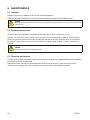
6 MAINTENANCE ...............................................................30
6.1 Overview ............................................................................................................. 30
6.2 Preventive maintenance ......................................................................................30
6.3 Corrective maintenance ......................................................................................30
6.4 Equipment preventive maintenance plan .............................................................31
7 PLASMA TORCH ..............................................................32
7.1 Specifications .....................................................................................................32
7.2 Introduction to Plasma .......................................................................................33
7.3 Torch maintenance ..............................................................................................34
8 TROUBLESHOOTING GUIDE ................................................35
9 PARTS LISTS .................................................................36
9.1 Consumable Parts for 60A Torch (P/N 0559337000) .......................................... 36
9.2 Options and Accessories ....................................................................................36
!
!
WARNING
Read and understand this entire Manual and your employer’s safety practices before installing,
operating, or servicing the equipment.
While the information contained in this Manual represents the Manufacturer's best judgment, the
Manufacturer assumes no liability for its use.
Published by:
ESAB
2800 Airport Rd.
Denton, TX 76208
Copyright 2020 by ESAB. All rights reserved.

6 0-5584
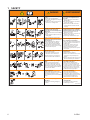
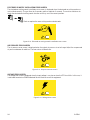
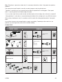
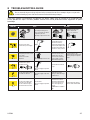
1 SAFETY
AVERTISSEMENT
WARNING
1. Cutting sparks can cause explosion
or fire.
1.1 Do not cut near flammables.
1.2 Have a fire extinguisher nearby and
ready to use.
1.3 Do not use a drum or other closed
container as a cutting table.
2. Plasma arc can injure and burn;
point the nozzle away from
yourself. Arc starts instantly when
triggered.
2.1 Turn o power before disassembling
torch.
2.2 Do not grip the workpiece near the
cutting path.
2.3 Wear complete body protection.
3. Hazardous voltage. Risk of electric
shock or burn.
3.1 Wear insulating gloves. Replace
gloves when wet or damaged.
3.2 Protect from shock by insulating
yourself from work and ground.
3.3 Disconnect power before servicing.
Do not touch live parts.
4. Plasma fumes can be hazardous.
4.1 Do not inhale fumes.
4.2 Use forced ventilation or local
exhaust to remove the fumes.
4.3 Do not operate in closed spaces.
Remove fumes with ventilation.
6. Become trained.
Only qualified personnel should
operate this equipment. Use torches
specified in the manual. Keep
non-qualified personnel and children
away.
5. Arc rays can burn eyes and injure
skin.
5.1 Wear correct and appropriate
protective equipment to protect
head, eyes, ears, hands, and body.
Button shirt collar. Protect ears from
noise. Use welding helmet with the
correct shade of filter.
7. Do not remove, destroy, or cover
this label.
Replace if it is missing, damaged,
or worn.
1. Les étincelles de coupage peuvent
provoquer une explosion ou un
incendie.
1.1 Ne pas couper près des matières
inflammables.
1.2 Un extincteur doit être à proximité
et prêt à être utilisé.
1.3 Ne pas utiliser un fût ou un autre
contenant fermé comme table de
coupage.
2. L’arc plasma peut blesser et brûler;
éloigner la buse de soi. Il s’allume
instantanément quand on l’amorce.
2.1 Couper l’alimentation avant de
démonter la torche.
2.2 Ne pas saisir la pièce à couper de la
trajectoire de coupage.
2.3 Se protéger entièrement le corps.
3. Tension dangereuse. Risque de
choc électrique ou de brûlure.
3.1 Porter des gants isolants. Remplacer
les gants quand ils sont humides ou
endommagés.
3.2 Se protéger contre les chocs en
s’isolant de la pièce et de la terre.
3.3 Couper l’alimentation avant
l’entretien. Ne pas toucher les pièces
sous tension.
4. Les fumées plasma peuvent être
dangereuses.
4.1 Ne pas inhaler les fumées.
4.2 Utiliser une ventilation forcée ou un
extracteur local pour dissiper les
fumées.
4.3 Ne pas couper dans des espaces clos.
Chasser les fumées par ventilation.
5. Les rayons d’arc peuvent brûler les
yeux et blesser la peau.
5.1 Porter un bon équipement de
protection pour se protéger la tête,
les yeux, les oreilles, les mains et le
corps. Boutonner le col de la chemise.
Protéger les oreilles contre le bruit.
Utiliser un masque de soudeur avec
un filtre de nuance appropriée.
6. Suivre une formation.
Seul le personnel qualifié a
le droit de faire fonctionner cet
équipement. Utiliser exclusivement
les torches indiquées dans le manual.
Le personnel non qualifié et les
enfants doivent se tenir à l’écart.
7. Ne pas enlever, détruire ni couvrir
cette étiquette.
La remplacer si elle est absente,
endommagée ou usée.
Art # A-13294

0-5584 7
2 INTRODUCTION
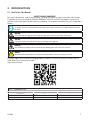
2.1 How To Use This Manual.
PROTECT YOURSELF AND OTHERS!
To ensure safe operation, read the entire manual, including the chapter on safety instructions and warnings.
Throughout this manual, the words DANGER, WARNING, CAUTION, and NOTE may appear. Pay particular
attention to the information provided under these headings. These special annotations are easily recognized as
follows:
NOTE!
An operation, procedure, or background information which requires additional emphasis or is helpful in ecient operation of
the system.
!!
WARNING
A procedure which, if not properly followed, may cause injury to the operator or others in the operating area.
!
!
CAUTION
A procedure which, if not properly followed, may cause damage to the equipment.
WARNING
Gives information regarding possible electrical shock injury. Warnings will be enclosed in a box such as this.
!
DANGER
Means immediate hazards which, if not avoided, will result in immediate, serious personal injury or loss of life.
Electronic copies of this manual can be downloaded in Acrobat PDF format by going to the ESAB web site
listed below: Enter manual part number.
http://www.esab.com
TABLE 2.1 - RECOMMENDED LENSES
Arc Current (Amps) Minimum Protector Matrix No. Suggested Matrix No. (comfort)
Less than 20 4 7
20-40 5 7
40-60 6 7

8 0-5584
2.2 HandyPlasma features
12 mm max HandyPlasma 35i
16 mm max HandyPlasma 45i
carbon steel
Front Panel Controls
The HandyPlasma equipment provides excellent cutting performance when used with the correct consumables and
plasma cutting procedures. The following instructions detail the appropriate safe configuration of the equipment and
provide directives to obtain the best efficiency and quality.
Carefully read these instructions before using.

0-5584 9
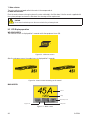
2.3 Equipment Identification/ User responsibility
HandyPlasma 35i
HandyPlasma 45i
OPERATING MANUAL
05/2020 - Revision: AA Manual No.: 0-5584
HandyPlasma 35i
HandyPlasma 45i
0559160135
0559160145
✅
✅
✅
✅
Inspect each item regarding possible damage during shipping. If the damage is evident, contact your distributor
and/or carrier before proceeding with the installation.
Washer
Diffuser
Electrode
Cutting nozzle
Shield Cup
Standoff Guide
Include all equipment identification numbers, along with a full description of the missing or parts damaged.

10 0-5584
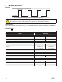
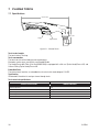
3 TECHNICAL DATA
Duty Cycle
10 minutes
WORK
Rest
1.5 minutes
8.5 minutes
WARNING!
The work cycle is the percentage of time during which the equipment can be operated without overheating.
Protection class
The IP code indicates the enclosure class, i.e. the degree of protection against penetration by solid objects or
water.
Application class
The symbol indicates that the power supply was designed for use in areas with high electrical risks.
TABLE 3.1
TECHNICAL DATA
INVERTER HANDYPLASMA
Equipment development technology Inverter
Equipment model HandyPlasma 35i HandyPlasma 45i
Efficiency 84% @35A/94V 84% @45A/98V
Idle state power consumption 35 W 35 W
Network voltage 220~240V - 1Ø
Network frequency 50/60 Hz
Current range 20 - 35 A (DC) 20 - 45 A (DC)
Work cycle
28 A / 91,2V @ 60%
35 A / 94V @ 35%
22 A / 88,8V @ 100%
35 A / 94 V @ 60%
45 A / 98 V @ 35%
30 A / 92 V @ 100%
Dimensions (W x L x H) 176 x 415 x 324 mm
Weight 13,5 kg
Recommended air input requirements 6-8 Bar (87-116 PSI)
Recommended air flow 110 LPM
Open circuit voltage 315V 315V
Operating temperature 0°C to 40°C
Power factor at the maximum current output 0.99
IP Rating IP 21S
Apparent Power 9 kVA 10 kVA
Recommended circuit breaker or fuses at maximum output 11 A 15,4 A
Rated power consumption 6.4KW 7.2 KW

0-5584 11
WARNING!
Do not operate this machine above its rated capacity.
WARNING!
The air supply must be free from oil, humidity, and other contaminants. Excessive oil and humidity may cause double arcs, quick
tip wear, or even complete torch failure. Contaminants may cause poor cutting performance and quick electrode wear. Optional
lters provide higher ltering capacity.
NOTE!
The IEC Classication is determined as specied by the International Electrotechnical Commission. These specications include
the output voltage calculation based on the equipment rated current. To allow easy comparison between pieces of equipment,
all manufacturers use this output voltage to establish the operation cycle.
15"
381 mm
6"
150 mm
15"
381 mm
6"
150 mm
Art # A-14040DIFF_2
415 mm
13.5 kg
176 mm
324 mm
Figure 3.1 - Dimensions and weight of the power supply
NOTE!
The weight includes the equipment, torch, consumables, input power cable, and work clamp.
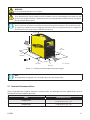
3.1 Generator Recommendations
When using generators to power the plasma cutting system, the following minimum specifications must be
considered to select the power generator.
TABLE 3.2
MODEL GENERATOR RATED OUTPUT
HandyPlasma 35i
8 kVA (with power factor of 0.8)
6.4 KW (with power factor of 1.0)
HandyPlasma 45i
9 kVA (with power factor of 0.8)
7.2 KW (with power factor of 1.0)

12 0-5584
4 INSTALLATION
4.1 General
The equipment must be installed by trained and qualified professionals.
WARNING!
This product was designed for industrial use. The user is responsible for taking the appropriate measures.
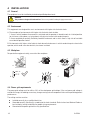
4.2 Environment
This equipment was designed for use in environments with higher risk of electric shock.
A. The examples of environments with higher risk of electric shock include:
1. Areas in which freedom of movement is restricted, and the operator is forced to work in a limited position
(on his knees, sitting down, or laying down) with physical contact with conductive parts.
2. Areas completely or partially limited by conductive elements and in which there is high risk of inevitable
or accidental operator contact.
B. Environments with higher risk of electric shock do not include areas in which conductive parts close to the
operator, which could cause elevated risk, have been insulated.
4.3 Workplace
To operate the equipment safely, ensure that the workplace:
A.
D.
0o C
40o C
✅
B.
E.
C.
4.4 Power grid requirements
The power grid voltage must be within ±10% of the rated power grid voltage. If the real power grid voltage is
outside this range, the welding current may change causing internal component failure and impaired equipment
performance.
The cutting machine must be:
■ Installed correctly, by a qualified electrician.
■ Grounded correctly (electrically) according to the local standards. Refer to Local and National Codes or
local authority having jurisdiction for proper wiring requirements.
■ Connected to the power grid with a duly specified fuse.

0-5584 13
WARNING!
All electrical work must be performed by a qualied expert electrician.
WARNING!
The grounding terminal is connected to the power supply body via the HandyPlasma plug. It must be connected to a grounding
point of the workplace electrical installation. Take care not to invert the input cable ground conductor (green/yellow cable) at
any of the main switch of circuit breaker phases, because this applies electrical voltage to the body.
NOTE!
Do not use the network neutral as ground.
All electrical connections must be firmly tightened in order to avoid risk of sparks, overheating, or circuit voltage
drop.
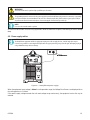
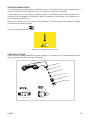
4.5 Power supply cables
NOTE!
The HandyPlasma equipment includes an appropriate input power cable to supply the 220~240 VAC single-phase input.
Customer is responsible for connecting the HandyPlasma to the appropriate voltage range from the grid. Attempting to plug in
voltage ABOVE this range will cause damage.
Figure 4.1 - HandyPlasma power supply
When the equipment input voltage is below the safe operation range, the Voltage Error Screens are displayed when
the cutting process is initiated.
If the power supply voltage exceeds the safe work voltage range continuously, the equipment service life may be
reduced.

14 0-5584
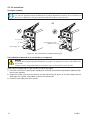
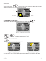
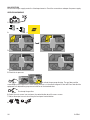
4.6 Air connections
Air adapter assembly:
NOTE!
For a secure seal, apply thread sealant to the tting threads, according to manufacturer’s instructions. Do not use Teon tape as a
thread sealer, as small particles of the tape may break o and block the small air passages in the torch.
C) 8 mm Pin
B) Clip
A) Gas Supply Hose
A) Gas Supply Hose with
Quick Disconnect
Figure 4.2 - Gas connection to compressed air input.
Using industrial compressed air in gas cylinders or a compressor
WARNING!
The cylinders must be equipped with adjustable high-pressure regulators, for output pressures of up to 6-8 bar and ows of at
least 110 LPM.
A compressor must be equipped with output pressure regulators of up to 6-8 bar and ows of at least 110 LPM.
When industrial compressed air in gas cylinders is used as gas supply:
1. Check the manufacturer’s specifications regarding the installation and maintenance procedures applied to high-
pressure gas regulators.
2. Inspect the cylinder valves to ensure that they are clean and free from oil, grease, or any other foreign materials.
Briefly open each cylinder valve to blow any dust that may be present.
3. Connect the gas supply hose to the cylinder.

0-5584 15
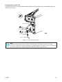
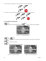
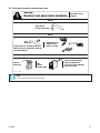
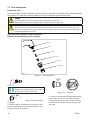
Installing Optional Inline Filter
An optional inline filter is recommended for improved filtering with compressed air and keeping moisture or
debris out of the torch.
D) 1/4” NPT port
C) Filter
B) Clip
A) Hose
Figure 4.3 - Connecting Inline Filter
NOTE!
Adjust the gas cylinder pressure between 6 and 8 bar. The internal diameter of the supply hose must be at least 6 mm.
For a secure seal, apply thread sealant to the tting threads, according to manufacturer’s instructions. Do not use Teon tape as a
thread sealer, as small particles of the tape may break o and block the small air passages in the torch.

16 0-5584
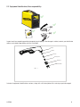
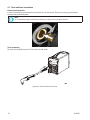
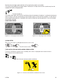
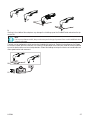
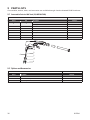
4.7 Torch and Lead connections
Ground Lead connection
Ensure connection to ground terminal with the 25 mm connector. The plasma cutting current ows
through the ground terminal.
NOTE!
It is essential that the plug is inserted and rotated into place securely to obtain a electrical connection.
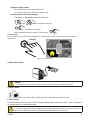
Torch connection
To install the HandyPlasma torch. Push sleeve in and rotate.
Figure 4.4 - Plasma torch connection

0-5584 17
5 OPERATION
5.1 Overview
The general safety regulations to handle the equipment are found in section 1. Read and understand the instruction
manual before installing or operating.
CAUTION!
The user is responsible for dening the process and respective cutting procedure of the consumables (wire, gas) and for the
results of the operation and application.
CAUTION!
Do not turn the power supply OFF during cutting (with load).
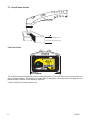
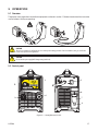
5.2 Control panel
2
1
3
4
5
2
6
8
7
Figure 5.1 - HandyPlasma 35i/45i

18 0-5584
1. Plasma torch adapter
The adapter is the connection point for the plasma cutting torch.
To remove the plasma cutting torch, rotate sleeve counter-clockwise and pull.
Trigger Switch
Tip
PIP Switch
Electrode
Figure 5.2 - Plasma torch connection
TABLE 5.1 Pinout table
SOCKET PIN FUNCTION
1 Torch trigger
2 Torch trigger
3 No connection
4 No connection
5 Tip
6 Tip
7 No connection
8 PIP switch
9 PIP switch
Socket central Electrode
Pinout table
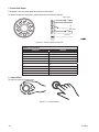
2. Control button
To select the menu or change values.
Figure 5.3 - Control button

0-5584 19
To adjust the cutting current:
• Turn clockwise to increase the cutting current;
• Turn counter-clockwise to reduce the cutting current.
To select an option in the menu displayed:
• The options are highlighted in sequence at each turn.
• To change the selection.
• To confirm the selection.
• Select the icon on the main screen. To exit the menu.
3. LCD screen
The front panel has an LCD screen to display the cutting mode, cutting current, air pressure, and error
information.
2 Seconds
Figure 5.4 - LCD screen
4. Work clamp terminal
2
3
1
CAUTION!
Loose terminal connections may cause overheating and fusion of the male terminal on the OKC female terminal.
5. ON/OFF switch
When the switch is ON, the front panel LCE screen lights up and the fan starts.
6. Gas connector
The equipment gas input may accept ¼” NPT male plugs and peg-type air connection nozzles, which are supplied in
the compressed air line connection package.
CAUTION!
For a secure seal, apply thread sealant to the tting threads, according to manufacturer’s instructions. Do not use Teon tape as a
thread sealer, as small particles of the tape may break o and block the small air passages in the torch.

20 0-5584
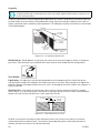
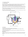
7. Water collector
The water collector equipped collects the water in the compressed air.
8. Water release valve
Push the water release valve up to release the water collected in the filter bowl. Use the wrench supplied with
the system package to release the filter bowl for cleaning or filter replacement.
CAUTION!
Do not remove bowl under pressure. Disconnect air line before performing this task.
5.3 LCD Display operation
WELCOME SCREEN
The welcome screen is displayed for 3 seconds while the equipment turns ON.
Figure 5.5 - Welcome screen
After the welcome screen, the model name is displayed for 3 seconds.
Figure 5.6 - Name screen according to the model
MAIN SCREEN
Current
Voltage
Output air pressure
Cutting mode
Trigger mode
Figure 5.7 - Main screen
La page est en cours de chargement...
La page est en cours de chargement...
La page est en cours de chargement...
La page est en cours de chargement...
La page est en cours de chargement...
La page est en cours de chargement...
La page est en cours de chargement...
La page est en cours de chargement...
La page est en cours de chargement...
La page est en cours de chargement...
La page est en cours de chargement...
La page est en cours de chargement...
La page est en cours de chargement...
La page est en cours de chargement...
La page est en cours de chargement...
La page est en cours de chargement...
La page est en cours de chargement...
La page est en cours de chargement...
-
 1
1
-
 2
2
-
 3
3
-
 4
4
-
 5
5
-
 6
6
-
 7
7
-
 8
8
-
 9
9
-
 10
10
-
 11
11
-
 12
12
-
 13
13
-
 14
14
-
 15
15
-
 16
16
-
 17
17
-
 18
18
-
 19
19
-
 20
20
-
 21
21
-
 22
22
-
 23
23
-
 24
24
-
 25
25
-
 26
26
-
 27
27
-
 28
28
-
 29
29
-
 30
30
-
 31
31
-
 32
32
-
 33
33
-
 34
34
-
 35
35
-
 36
36
-
 37
37
-
 38
38


ESAB HandyPlasma 35i Manuel utilisateur
- Catégorie
- Système de soudage
- Taper
- Manuel utilisateur
- Ce manuel convient également à
dans d''autres langues
- English: ESAB HandyPlasma 35i User manual
Documents connexes
-
ESAB HandyPlasma 35i, HandyPlasma 45i Manuel utilisateur
-
ESAB HandyPlasma®380 Plasmarc™ Cutting System Manuel utilisateur
-
-
-
ESAB PT-31XL and PT-31XLPC Plasma Arc Cutting Torches Manuel utilisateur
-
-
-
-
-