Milwaukee M18 FMS254-0 Manuel utilisateur
- Catégorie
- Outils électroportatifs
- Taper
- Manuel utilisateur

Cat. No.
0)06
M18 FUEL™ 0010" DUAL BEVEL COMPOUND SLIDING
MITR( SAW
OPERATOR'S MANUAL
To reduce the risk of injury, user must read and understand operator's manual.
WARNING

2
GENERAL POWER TOOL
SAFETY WARNINGS
WARNING
Read all safety warnings, instruc-
WLRQV LOOXVWUDWLRQV DQG VSHFL¿FD-
tions provided with this power tool. Failure to
IROORZ
DOO
LQVWUXFWLRQV
OLVWHG
EHORZ
PD\
UHVXOW
LQ
HOHFWULF
VKRFN
¿UH
DQGRU
VHULRXV
LQMXU\
6DYH
DOO
warnings and instructions for future reference.
The term "power tool" in the warnings refers to
\RXU
PDLQVRSHUDWHG
FRUGHG
SRZHU
WRRO
RU
EDW
-
tery-operated (cordless) power tool.
WORK AREA SAFETY
• Keep work area clean and well lit. Cluttered or dark
areas invite accidents.
• Do not operate power tools in explosive atmo
-
VSKHUHVVXFKDVLQWKHSUHVHQFHRIÀDPPDEOH
OLTXLGVJDVHVRUGXVWPower tools create sparks
which may ignite the dust or fumes.
.HHSFKLOGUHQDQGE\VWDQGHUVDZD\ZKLOHRSHUDWLQJ
a power tool. Distractions can cause you to lose control.
ELECTRICAL SAFETY
• Power tool plugs must match the outlet. Never modify
the plug in any way. Do not use any adapter plugs with
earthed (grounded) power tools. 8QPRGL¿HGSOXJV
and matching outlets will reduce risk of electric shock.
$YRLG ERG\ FRQWDFW ZLWK HDUWKHG RU JURXQGHG
surfaces, such as pipes, radiators, ranges and
refrigerators. There is an increased risk of electric
shock if your body is earthed or grounded.
• Do not expose power tools to rain or wet condi
-
tions. Water entering a power tool will increase the
risk of electric shock.
'R QRW DEXVH WKH FRUG 1HYHU XVH WKH FRUG IRU
carrying, pulling or unplugging the power tool.
Keep cord away from heat, oil, sharp edges or
moving parts. Damaged or entangled cords increase
the risk of electric shock.
• When operating a power tool outdoors, use an exten
-
VLRQFRUGVXLWDEOHIRURXWGRRUXVHUse of a cord suit-
able for outdoor use reduces the risk of electric shock.
• If operating a power tool in a damp location is
XQDYRLGDEOHXVHDJURXQGIDXOWFLUFXLWLQWHUUXSWHU
(GFCI) protected supply. Use of an GFCI reduces
the risk of electric shock.
PERSONAL SAFETY
• Stay alert, watch what you are doing and use
common sense when operating a power tool. Do
not use a power tool while you are tired or under
WKHLQÀXHQFHRIGUXJVDOFRKRORUPHGLFDWLRQA
moment of inattention while operating power tools
may result in serious personal injury.
8VHSHUVRQDOSURWHFWLYHHTXLSPHQW$OZD\VZHDU
eye protection. Protective equipment such as a dust
mask, non-skid safety shoes, hard hat or hearing
protection used for appropriate conditions will reduce
personal injuries.
• Prevent unintentional starting. Ensure the switch
LVLQWKHRIISRVLWLRQEHIRUHFRQQHFWLQJWRSRZHU
VRXUFHDQGRUEDWWHU\SDFNSLFNLQJXSRUFDUU\LQJ
the tool. &DUU\LQJSRZHUWRROVZLWK\RXU¿QJHURQWKH
switch or energiVing power tools that have the switch
on invites accidents.
5HPRYHDQ\DGMXVWLQJNH\RUZUHQFKEHIRUHWXUQLQJ
the power tool on. A wrench or a key left attached to a ro
-
tating part of the power tool may result in personal injury.
'RQRWRYHUUHDFK.HHSSURSHUIRRWLQJDQGEDODQFH
at all times. This enables better control of the power
tool in unexpected situations.
• Dress properly. Do not wear loose clothing or
jewelry. Keep your hair and clothing away from
moving parts. Loose clothes, jewelry or long hair can
be caught in moving parts.
• If devices are provided for the connection of dust
extraction and collection facilities, ensure these
are connected and properly used. Use of dust
collection can reduce dust-related hazards.
'RQRWOHWIDPLOLDULW\JDLQHGIURPIUHTXHQWXVHRI
WRROVDOORZ\RXWREHFRPHFRPSODFHQWDQGLJQRUH
tool safety principles. A careless action c
an cause
severe injury within a fraction of a second.
POWER TOOL USE AND CARE
• Do not force the power tool. Use the correct power tool
for your application. The correct power tool will do the
job better and safer at the rate for which it was designed.
• Do not use the power tool if the switch does not turn
it on and off. Any power tool that cannot be controlled
with the switch is dangerous and must be repaired.
• Disconnect the plug from the power source and/
RUUHPRYHWKHEDWWHU\SDFNLIGHWDFKDEOH IURP
WKHSRZHUWRROEHIRUHPDNLQJDQ\DGMXVWPHQWV
changing accessories, or storing power tools.
Such preventive safety measures reduce the risk of
starting the power tool accidentally.
• Store idle power tools out of the reach of children and
do not allow persons unfamiliar with the power tool
or these instructions to operate the power tool. Pow
-
er tools are dangerous in the hands of untrained users.
• Maintain power tools and accessories. Check for
PLVDOLJQPHQWRUELQGLQJRIPRYLQJSDUWVEUHDNDJH
of parts and any other condition that may affect
the power tool’s operation. If damaged, have the
SRZHU WRRO UHSDLUHG EHIRUH XVH Many accidents
are caused by poorly maintained power tools.
• Keep cutting tools sharp and clean. Properly
maintained cutting tools with sharp cutting edges are
less likely to bind and are easier to control.
• Use the po
ZHUWRRODFFHVVRULHVDQGWRROELWVHWF
in accordance with these instructions, taking into
DFFRXQWWKHZRUNLQJFRQGLWLRQVDQGWKHZRUNWREH
performed. Use of the power tool for operations different
from those intended could result in a hazardous situation.
• Keep handles and grasping surfaces dry, clean
and free from oil and grease. Slippery handles and
grasping surfaces do not allow for safe handling and
control of the tool in unexpected situations.
BATTERY TOOL USE AND CARE
5HFKDUJHRQO\ZLWKWKHFKDUJHUVSHFL¿HGE\WKH
manufacturer. A charger that is suitable for one type
RIEDWWHU\SDFNPD\FUHDWHDULVNRI¿UHZKHQXVHG
with another battery pack.
8VHSRZHUWRROVRQO\ZLWKVSHFL¿FDOO\GHVLJQDWHG
EDWWHU\SDFNVUse of any other battery packs may
FUHDWHDULVNRILQMXU\DQG¿UH
:KHQ EDWWHU\ SDFN LV QRW LQ XVH NHHS LW DZD\
IURPRWKHUPHWDOREMHFWVOLNHSDSHUFOLSVFRLQV
NH\VQDLOVVFUHZVRURWKHUVPDOOPHWDOREMHFWV
that can make a connection from one terminal to
another. Shorting the battery terminals together may
FDXVHEXUQVRUD¿UH
8QGHUDEXVLYHFRQGLWLRQVOLTXLGPD\EHHMHFWHG
IURPWKH EDWWHU\DYRLGFRQWDFW ,IFRQWDFWDFFL
-
GHQWDOO\RFFXUVÀXVKZLWKZDWHU,IOLTXLGFRQWDFWV
eyes, additionally seek medical help. Liquid ejected
from the battery may cause irritation or burns.
'RQRWXVHDEDWWHU\SDFNRUWRROWKDWLVGDPDJHGRU
PRGL¿HG'DPDJHGRUPRGL¿HGEDWWHULHVPD\H[KLELW
XQSUHGLFWDEOHEHKDYLRUUHVXOWLQJLQ¿UHH[SORVLRQRU
risk of injury.

3
'RQRWH[SRVHDEDWWHU\SDFNRUWRROWR¿UHRUH[FHV-
sive temperature. ([SRVXUHWR¿UHRUWHPSHUDWXUH
above °& (°)) may cause explosion.
• Follow all charging instructions and do not charge
WKHEDWWHU\SDFNRUWRRORXWVLGHWKHWHPSHUDWXUH
UDQJHVSHFL¿HGLQWKHLQVWUXFWLRQVCharging im
-
SURSHUO\RUDWWHPSHUDWXUHVRXWVLGHWKHVSHFL¿HGUDQJH
PD\GDPDJHWKHEDWWHU\DQGLQFUHDVHWKHULVNRI¿UH
SERVICE
+DYH\RXUSRZHUWRROVHUYLFHGE\DTXDOL¿HGUHSDLU
person using only identical replacement parts.
This will ensure that the safety of the power tool is
maintained.
1HYHU VHUYLFH GDPDJHG EDWWHU\ SDFNV Service
of battery packs should only be performed by the
manufacturer or authoriVed service providers.
SPECIFIC SAFETY RULES FOR
MITR( SAWS
• MitrH saws are intended to cut wood or wood-like
SURGXFWVWKH\FDQQRWEHXVHGZLWKDEUDVLYHFXWRII
ZKHHOVIRUFXWWLQJIHUURXVPDWHULDOVXFKDVEDUV
rods, studs, etc. Abrasive dust causes moving parts
such as the lower guard to jam. Sparks from abrasive
cutting will burn the lower guard, the kerf insert and
other plastic parts.
• Use clamps to support the workpiece whenever
SRVVLEOH ,I VXSSRUWLQJ WKH ZRUNSLHFH E\ KDQG
you must always keep your hand at least 100 mm
IURPHLWKHUVLGHRIWKHVDZEODGH'RQRWXVHWKLV
VDZWRFXWSLHFHVWKDWDUHWRRVPDOOWREHVHFXUHO\
FODPSHGRUKHOGE\KDQGIf your hand is placed too
close to the saw blade, there is an increased risk of
injury from blade contact.
7KHZRUNSLHFHPXVWEHVWDWLRQDU\DQGFODPSHGRU
KHOGDJDLQVWERWKWKHIHQFHDQGWKHWDEOH'RQRW
IHHGWKHZRUNSLHFHLQWRWKHEODGHRUFXW³IUHHKDQG´
in any way. Unrestrained or moving workpieces could
be thrown at high speeds, causing injury.
• Push the saw through the workpiece. Do not pull
the saw through the workpiece. To make a cut, raise
the saw head and pull it out over the workpiece
without cutting, start the motor, press the saw head
down and push the saw through the workpiece.
Cutting on the pull stroke is likely to cause the saw
blade to climb on top of the workpiece and violently
throw the blade assembly towards the operator.
• Never cross your hand over the intended line of
FXWWLQJHLWKHU LQ IURQWRU EHKLQG WKH VDZEODGH
Supporting the workpiece “cross handed” i.e. holding
the workpiece to the right of the saw blade with your
left hand or vice versa is very dangerous.
'RQRWUHDFKEHKLQGWKHIHQFHZLWKHLWKHUKDQG
closer than 100 mm from either side of the saw
EODGHWRUHPRYHZRRGVFUDSVRUIRUDQ\RWKHU
UHDVRQZKLOHWKHEODGHLVVSLQQLQJThe proximity
of the spinning saw blade to your hand may not be
obvious and you may be seriously injured.
,QVSHFW \RXU ZRUNSLHFH EHIRUH FXWWLQJ ,I WKH
ZRUNSLHFHLVERZHGRUZDUSHGFODPSLWZLWKWKH
RXWVLGHERZHGIDFHWRZDUGWKHIHQFH$OZD\VPDNH
FHUWDLQWKDWWKHUHLVQRJDSEHWZHHQWKHZRUNSLHFH
IHQFHDQGWDEOHDORQJWKHOLQHRIWKHFXWBent or
warped workpieces can twist or shift and may cause
binding on the spinning saw blade while cutting. There
should be no nails or foreign objects in the workpiece.
'RQRWXVHWKHVDZXQWLOWKHWDEOHLVFOHDURIDOOWRROV
wood scraps, etc., except for the workpiece. Small
debris or loose pieces of wood or other objects that con
-
tact the revolving blade can be thrown with high speed.
•
Cut only one workpiece at a time. Stacked multiple
workpieces cannot be adequately clamped or braced
and may bind on the blade or shift during cutting.
• Ensure the mitrH saw is mounted or placed on a level,
¿UPZRUNVXUIDFHEHIRUHXVH$OHYHODQG¿UPZRUNVXU
-
face reduces the risk of the mitrH saw becoming unstable.
3ODQ\RXUZRUN(YHU\WLPH\RXFKDQJHWKHEHYHO
RUPLWUHDQJOHVHWWLQJPDNHVXUHWKHDGMXVWDEOH
fence is set correctly to support the workpiece and
ZLOOQRWLQWHUIHUHZLWKWKHEODGHRUWKHJXDUGLQJ
system. Without turning the tool “ON” and with no
workpiece on the table, move the saw blade through
a complete simulated cut to assure there will be no
interference or danger of cutting the fence.
3URYLGHDGHTXDWHVXSSRUWVXFKDVWDEOHH[WHQVLRQV
saw horses, etc. for a workpiece that is wider or
ORQJHU WKDQ WKH WDEOH WRS Workpieces longer or
wider than the mitrH saw table can tip if not securely
supported. If the cut-off piece or workpiece tips, it can
lift the lower guard or be thrown by the spinning blade.
'RQRWXVHDQRWKHUSHUVRQDVDVXEVWLWXWHIRUD
WDEOHH[WHQVLRQRUDVDGGLWLRQDOVXSSRUWUnstable
support for the workpiece can cause the blade to bind
or the workpiece to shift during the cutting operation
pulling you and the helper into the spinning blade.
7KHFXWRIISLHFHPXVWQRWEHMDPPHGRUSUHVVHG
E\DQ\PHDQVDJDLQVWWKHVSLQQLQJVDZEODGH If
FRQ¿QHGLHXVLQJOHQJWKVWRSVWKHFXWRIISLHFHFRXOG
get wedged against the blade and thrown violently.
• Always use a clamp or a fixture designed to
properly support round material such as rods or
WXELQJRods have a tendency to roll while being cut,
causing the blade to “bite” and pull the work with your
hand into the blade.
/HW
WKHEODGHUHDFKIXOOVSHHGEHIRUHFRQWDFWLQJWKH
workpiece. This will reduce the risk of the workpiece
being thrown.
,IWKHZRUNSLHFHRUEODGHEHFRPHVMDPPHGWXUQ
the mitre saw off. Wait for all moving parts to stop
and disconnect the plug from the power source
DQGRU UHPRYH WKH EDWWHU\ SDFN 7KHQ ZRUN WR
free the jammed material. Continued sawing with
a jammed workpiece could cause loss of control or
damage to the mitrH saw.
$IWHU¿QLVKLQJWKHFXWUHOHDVHWKHVZLWFKKROG
WKHVDZKHDGGRZQDQGZDLWIRUWKHEODGHWRVWRS
EHIRUHUHPRYLQJWKHFXWRIISLHFHReaching with
your hand near the coasting blade is dangerous.
+ROGWKHKDQGOH¿UPO\ZKHQPDNLQJDQLQFRPSOHWH
FXWRUZKHQUHOHDVLQJWKHVZLWFKEHIRUHWKHVDZ
head is completely in the down position. The
braking action of the saw may cause the saw head to
be suddenly pulled downward, causing a risk of injury.
0DLQWDLQ ODEHOV DQG QDPHSODWHV These carry
important information. If unreadable or missing, contact
a 0,/:$8.((
service facility for a replacement.
•
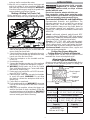
WARNING
Some dust created by power sanding,
sawing, grinding, drilling, and other
construction activities contains chemicals known to
cause cancer, birth defects or other reproductive harm.
Some examples of these chemicals are:
• lead from lead-based paint
• crystalline silica from bricks and cement and other
masonry products, and
• arsenic and chromium from chemically-treated lumber.
Your risk from these exposures varies, depending on
how often you do this type of work. To reduce your
exposure to these chemicals: work in a well ventilated
area, and work with approved safety equipment, such
as those dust masks that are specially designed to
¿OWHURXWPLFURVFRSLFSDUWLFOHV

4
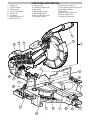
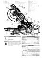
1. Saw head
2. Trigger handle
3. Lower guard
4. Fence hand holds
5. Fences (2)
6. Turntable
7. Mounting holes (4)
8. MitrH lock lever
FUNCTIONAL DESCRIPTION
9. Detent lever
10. Detent override knob
11. Kerf plate
12.MitrH angle pointer
13.MitrH angle scale
14. No Hands Zone circle
15.Carrying handles
16. Fence lock knobs (2)
17.Face board mounting holes (4)
18. Workpiece clamp
19.Slide rails
20. Bevel angle pointers (2)
21. Bevel angle scale
22. Head lock-down pin
7
11
1
22
21
15
12
10
9
6
5
2
13
16
3
17
18
19
20
8
14
4

5
SYMBOLOGY
Volts
Direct Current
No Load Revolutions per Minute (RPM)
No Hands Zone - Keep hands out of
the No Hands Zone at all times during
use. Contact with blade will result in
serious injury.
SPECIFICATIONS
Cat. No. ...........................................M18FMS254-0
Volts..............................................................18 DC
Battery Type .................................................M18™
Charger Type................................................M18™
No Load RPM ..................................................4000
Arbor Size .....................................................
...
30 mm
Blade Size .........................................254 mm (10")
Blade Thickness (Kerf) ................ Max 3 mm (1/8")
Weight ........................................................ 20.4 kg
CAPACITIES
Mitre Cuts
Max Height at 90
o
..............146 mm H at 39 mm W
Max Height at 45
o
Mitre Left.........146 mm H at 25 mm W Left Side
.......146 mm H at 31 mm W Right Side
Mitre Right .......146 mm H at 33 mm W Left Side
........91 mm H at 205 mm W Right Side
Max Width at 90
o
..............289 mm W at 91 mm H
Max Width at 45
o
............. 205 mm W at 91 mm H
Compound Cuts ..............45
o
Mitre and 45
o
Bevel
Left ...................................205 mm W at 51 mm H
Right ............................... 205 mm W at 38 mm H
Groove Cuts Max Depth...........................63 mm H
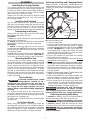
23. Trigger
24. T
rigger lock
25. Cut-line indicator switch
26. Handle
27.Depth stop adjustment knob
28. Bevel adjustment lever
29. Dust chute
30. Dust bag
31. Slide rail transport lock
32. Kickstand
33. Hand stop
34. Workpiece clamp sockets (2)
35.Wrench storage
36. 6 mm Hex Wrench
37. Chop lock lever
38. Depth stop lever
39. Spindle lock
40. Light
29
27
28
26
23
25
30
39
38
40
37
24
33
32
31
34
35
36

6
ASSEMBLY
Installing the Carrying Handles
The carrying handles are used for transport as well
as support extensions for cutting longer workpieces.
Use the four bolts to attach the carrying handles to
each side of the mitrH saw table, using the blade
wrench provided. Tighten securely.
Always lock the slide rails and lock down the saw
head before transporting tool. Only carry tools by
the carrying handles.
Installing the Kickstand
Lay the mitrH saw on its side. Insert the kickstand
(the bend should angle toward the ground) into the
two holes under the slide rails. Push the kickstand
in until it won't go any further. To secure, insert and
tighten the screw into the end of one kickstand prong.
Transporting and Storing
Always lock the saw head and slide rails before
transporting and storing the tool.
Saw Head
To lock, press and hold down the saw head and then
push in the lock-down pin.
To unlock, press and hold down the saw head and
pull out the lock-down pin. Raise the saw head.
Slide Rails
To unlock, loosen the slide rail lock by turning it
counterclockwise. NOTE: If the slide does not appear
to work when the slide rail lock is loosened, the chop
lock may be locked.
To lock, slide the saw head forward and tighten the
slide rail lock by turning it clockwise. CAUTION! Do
not use the chop lock to lock the rails for transport.
Mounting the MitrH Saw
To prevent the tool from sliding, falling or tipping
from a raised work surface during operation, the saw
should be mounted to a supporting surface such as
a level, sturdy work table, bench, or mitrH saw stand.
Position the saw and workbench to allow adequate
room for cross-cutting long workpieces. To mount
WKH VDZ WR D ÀDW VXUIDFH LQVHUW IDVWHQHUV WKURXJK
the holes in the corners of the saw base and secure.
Follow manufacturer instructions when mounting to
a mitrH saw stand.
Dust collection
WARNING
Collected sawdust from coated
(polyurethanes, linseed oil, etc.)
ZRUNSLHFHV FDQ VHOILJQLWH LQ WKH GXVW EDJ RU
HOVHZKHUHDQGFDXVH¿UH7RUHGXFHWKHULVNRI
¿UH HPSW\ WKH GXVW EDJ IUHTXHQWO\ DQG QHYHU
store or leave a saw without totally emptying its
GXVWEDJ
The dust port at the back of the saw can be con-
nected to a standard workshop vacuum hose or the
included dust bag. Leave the dust bag open to direct
dust down into a garbage can.
To install, push and twist the hose or dust bag onto
the dust port.
Using Face Boards
When using face boards, secure them using the
mounting holes in the fences. Face boards place dis-
tance between the fence and the workpiece, providing
improved support for some workpieces. Workpiece
splintering can be reduced by using face boards.
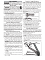
Remove battery pack.
2. Lower the saw head.
3. Raise the lower guard and hold up while raising
the saw head. Let go of the lower guard. The lower
guard will remain up in the blade-changing OPEN
position. WARNING! Be careful not to lower the
guard head while changing the blade; the lower
guard will fall back into place to cover the blade
DQGFRXOGSLQFKKDQGVDQG¿QJHUV
4. Press in the spindle lock and rotate the spindle/
blade until the lock engages.
5. Use the wrench to loosen and remove the left-hand
thread blade bolt (clockwise).
6. 5HPRYHWKHRXWHUEODGHÀDQJHDQGEODGH:LSH
WKHÀDQJHVDQGVSLQGOHWRUHPRYHGXVWDQGGHEULV
Inspect the parts for damage. Replace if needed.
7. Match the arrow direction on the blade with the
arrow direction on the lower guard. Slide the blade
onto the spindle.
8. ,QVWDOOWKHRXWHUEODGHÀDQJH7KHÀDWVLGHRIWKH
ÀDQJHPXVWUHVWDJDLQVWWKHEODGH
9. Press in the spindle lock and rotate the blade until
the lock engages. Insert and securely tighten the
blade bolt (counterclockwise) with the wrench.
10. Move hands out of the guard area and lower
the saw head. The lower guard will fall back into
place; verify it moves freely. Check the clearance
between the blade, kerf plate, and fences.
WARNING
Recharge only with the charger
VSHFL¿HGIRUWKHEDWWHU\)RUVSH-
FL¿FFKDUJLQJLQVWUXFWLRQVUHDGWKHRSHUDWRU¶V
PDQXDOVXSSOLHGZLWK\RXUFKDUJHUDQGEDWWHU\
Removing/Inserting the Battery
To remove the battery, push in the release buttons
and pull the battery pack away from the tool.
WARNING
$OZD\VUHPRYHEDWWHU\SDFNEHIRUH
changing or removing accessories.
To insert the battery, slide the pack into the body
of the tool. Make sure it latches securely into place.
WARNING
2QO\XVHDFFHVVRULHVVSHFL¿FDOO\
recommended for this tool. Others
PD\EHKD]DUGRXV
Selecting, Installing, and Changing Blades
Always use clean, sharp blades. Dull blades tend to
overload the tool, bind, and cause pinching. Use only
254mm (10")sliding mitre saw blades rated at least
Outer
Blade
bolt
Blade
Guard in
blade-changing
OPEN position
4000 RPM.

7
ADJUSTMENTS
WARNING
$OZD\V UHPRYH WKH EDWWHU\ SDFN
EHIRUH FKDQJLQJ DFFHVVRULHV RU
making adjustments. Do not defeat the guards.
No Hand Zone
WARNING
Keep hands out of the No
Hands Zone at all times
GXULQJXVH&RQWDFWZLWKEODGHZLOOUHVXOW
in serious injury.
If your hand is placed too close to the saw blade, there
is an increased risk of injury from blade contact. Use
the No Hand Zone indicators to ensure hands are kept
a safe distance from the blade.
No Hand Zone Indicators:
• No Hands Zone Circle (groove around turntable)
• Fence Hand Holds (notches on top of fences)
• Hand Stops (used when fence is removed)
Never cross your hand over the intended line of cutting
either in front or behind the saw blade. The proximity
of the spinning saw blade to your hand may not be
obvious and you may be seriously injured. Saw head
may slide/move, putting your safety at risk. Always
wait for the blade to stop completely before raising
the head,
moving workpiece or changing settings
.
Select the Workpiece Carefully
Be cautious of pitchy, knotty, wet or warped work-
pieces. These materials are likely to create pinching
conditions. Workpieces that bow and pinch may
result in kick back. Inspect for and remove nails
before cutting. Always keep blades clean and sharp;
otherwise the blade produces a narrow kerf and is
likely to be pinched by the workpiece. This tool is not
recommended for cutting ferrous metals such as iron
and steel. See Applications for a more complete list
of materials that can be cut.
Support the Workpiece Properly
Always support the workpiece during operation.
Otherwise, the workpiece may pull up and into the
saw. WARNING!
Use clamps to support the work-
piece whenever possible to keep hands far from
the blade. Do not use this saw to cut pieces that are
held by hand or too small to be securely clamped.
1. Use the Fence:+ROGWKHZRUNSLHFHÀXVKDJDLQVW
the fence to provide a straight path for the saw
blade. This will help eliminate the tendency for
the blade teeth to bind. The fence can be used
as a support for mitrH, bevel and compound cuts.
WARNING! Keep hands out of the No Hands Zone
at all times during use. Use the fence hand holds
to ensure your hands do not enter the No Hands
Zone.
2. Use the workpiece clamp: Clamp the workpiece
to the table with the included clamp. The clamp
can be moved to either side of the table.
a. Insert the clamp bar into either clamp socket
behind the fences.
b. Turn the clamp bar until it seats fully into the
socket.
c. Rotate the clamp around so the screw is above
the table.
d. Tighten the clamp screw to secure the work-
piece to the table.
3. Use a C-clamp: Clamp the workpiece to the fence
with a C-clamp.
Detent lever
Detent override knob
MitrH lock lever
1. Remove battery pack.
2. Lift up the mitrH lock lever to release the turntable.
3. Lift the detent lever and rotate the turntable to the
detent angle closest to the desired angle.
4. 7RPDNHD¿QHDGMXVWPHQWWRWKHPLWUHDQJOH
a. Lift the detent lever.
b. Rotate the detent override knob forward.
c. Rotate the turntable to the exact angle.
5. Press down the mitrH lock lever to lock the adjust-
ment in place and avoid shifting during use.
Adjusting the Bevel Angle
The bevel angle can be set using detents for commonly
cut angles (0°, 22.5°, 33.85°, 45°), as well as adjusted
to any angle in between by using the bevel angle scale.
The bevel mechanism also has several degrees of
overtravel on both the left and right.
1. Remove battery pack.
2. Lift the bevel adjustment lever to the Unlock
position.
3. Tilt the saw head left or right to the desired angle.
4. To use one of the preset angles (0°, 22.5°, 33.85°,
45°), press the bevel adjustment lever half-way
down. Continue to tilt the saw head until the preset
"clicks" into place.
5. Press down the bevel adjustment lever to the Lock
position.
Unlock
Lock
Bevel Adjustment Lever
Support of Longer Workpieces
Adjusting the Mitre Angle
Longer workpieces need support along their full
length. If you are using the saw on a level work
bench, prop up the workpiece to a height of 89 mm
(3-1/2") (50 mm x 100 mm set on its side) from the
bottom of the saw feet. There are also many
aftermarket work tables specifically designed for
mitre saws that provide supports for all types of
workpieces.
The mitre angle can be set using detents for commonly cut
angles (0°, 15°, 22.5° 31.6°, 45°, 50° left, and 60° right), as
well as finely adjusted to any angle to compensate for a
custom situation.

8
Adjusting the Fences
Every time the bevel or mitre angle settings are changed,
make sure the fences are set correctly.
Fences MUST:
•
Support the workpiece
•
Not interfere with the blade or lower guard
•
Be adjusted to keep hands out of the No Hand Zone
To adjust the Fences
1. Remove battery pack.
2. Loosen the fence lock knobs.
3. Slide the fences side-to-side to the desired posi-
tion to allow for a bevel or compound mitrH cut.
Position the fences properly for maximum work
support while maintaining hand safety. WARNING!
Ensure fence hand holds are positioned to keep
hands out of the No Hand Zone.
4. Tighten the fence lock knobs securely before mak-
ing a cut.
NOTE: If either fence has any movement forward
to backward, tighten the fence set screw, located
on the back of each fence slot.
5. With the saw OFF and the workpiece removed
from the table, slowly lower the saw head com-
pletely to ensure the guard and blade do not con-
tact the fences when making mitrH and bevel cuts.
Guards
The lower guard should cover the blade when the
saw head is up and it should move freely and open
automatically as the saw head is lowered into the
workpiece. WARNING! Never disable or remove
guards. Only push the lower guard into the OPEN
position when changing blades.
If the lower guard appears loose, sticks, or does not
cover the blade when the saw head is up, take the saw
to an authoriVed service centrH for repairs.
Ensure the Fences are adjusted properly to allow for
free-movement of the guards during the complete
movement of the cut.
Setting for Chop Cuts
The slides can be locked and the saw head set in
the proper position to use the saw for chop cuts (cuts
not requiring the use of the slides).
1. To lock, push Chop Lock to
.
2. Slide saw head until it locks into place.
3. To unlock, push Chop Lock to
.
Adjusting the Depth of Cut
The depth of the cut can be adjusted for groove or
rabbet cuts.
1. Remove battery pack.
2. To set the depth of cut,
rotate the depth stop
lever up.
3.
Lower the saw head to
the desired depth of cut.
4. Rotate the depth stop
adjustment knob un-
til it contacts the le-
ver. Lock in the depth
using the lock nut.
5. Make a test cut to verify
the depth of cut is cor-
rect.
6. To remove the depth
of cut limit, loosen the
lock nut by turning counterclockwise and rotate
the lever back.
OPERATION
WARNING
To reduce the risk of injury, always
wear safety goggles or glasses
ZLWKVLGHVKLHOGV.HHSKDQGVDQGERG\RXWRI
WKHSDWKRIWKHVDZEODGH&RQWDFWZLWKEODGHZLOO
result in serious injury. Check guarding system
to make sure it is functioning correctly. Do not
operate saw without guards in place. Do not
perform any operation freehand. Never reach
DURXQGVDZEODGH7XUQRIIWRRODQGZDLWIRUVDZ
EODGHWRVWRSEHIRUHPRYLQJZRUNSLHFHRUFKDQJ-
ing settings. Tighten all adjustments prior to use.
Cut Line Indicator
The cut-line indicator shines down the blade, casting
a shadow where the blade will meet the workpiece.
No calibration/adjustments will be needed as the
shadow will always be true to the blade location.
Use the cut-line indicator switch to turn on the light
before making a cut. The light will go off automatically
about 10 seconds after use.
WARNING
To reduce the risk of injury, do not
UHO\RQWKHEUDNHDVDVDIHW\IHD-
WXUH$OZD\V ZDLW XQWLO WKH EODGH VWRSV FRP-
SOHWHO\EHIRUHDOORZLQJDQ\WKLQJQHDUWKHEODGH
To reduce the risk of injury, make sure all adjust-
PHQWVDUHVHFXUHO\ORFNHGEHIRUHPDNLQJDFXW
Starting and Stopping the Tool
$OZD\V KROG WKH WULJJHUKDQGOH ¿UPO\ EHFDXVH WKH
starting and stopping action of the motor may cause
the handle to move up or down slightly. WARNING!
Always press down mitrH lock lever and tighten all
adjustments prior to use. WARNING! Ensure hands
are out of the No Hands Zone.
1. To start the motor, push down the trigger lock and
pull the trigger.
2. To stop the motor, release the trigger. The elec-
tric brake will stop the blade in about 4 seconds.
WARNING! The brake is not a substitute for the
guards and could fail; always wait for the blade to
stop completely before removing the blade from
the workpiece. If the brake fails to stop the blade or
misses frequently, return the tool to a 0,/:$8.((
service facility for repair.
Making a Chop Cut
Cut workpieces with chop cuts whenever possible.
Only use sliding cuts (cross cuts) when necessary.
1. Use the chop lock to set the saw in the chop cut
position.
2. Select the desired angles and adjust the fences to
ensure fence hand holds are positioned to keep
hands out of the No Hand Zone.
3. Place the workpiece on the turntable and line up
the cut.
4. Insert battery pack.
5. Support the workpiece using any of the methods
described in "Support the Workpiece Properly".
6. WARNING! Keep hands out of the No Hands
Zone at all times during use. Contact with blade
will result in serious injury.
7. Start the motor. Wait a few seconds for the blade
to reach full speed. Then gently lower the saw
head into the workpiece all the way through the
cut. WARNING! Do not allow the blade to contact
the workpiece while tool is ramping up.
8. Always allow the saw to do the work. Forcing the
Depth-stop lever
Lock nut
Knob

9
tool may stall or overheat the motor.
9. After the cut is complete, release the trigger and
wait for the blade to stop completely. Raise the
saw head and remove the workpiece. WARNING!
If small cut-off pieces get caught in the guard area,
remove battery pack before clearing.
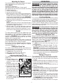
Making a Sliding Cut (Cross Cut)
Wider workpieces can be cut using the sliding
mechanism. Always use chop cut whenever possible.
4
2
3
1
1. Make sure that the chop lock is unlocked, the
slide rail transport lock is loose, and the saw head
moves freely back and forth.
2. Select the desired angles and adjust the fences to
ensure fence hand holds are positioned to keep
hands out of the No Hand Zone.
3. Place the workpiece on the turntable and line
up the cut.
4. Insert battery pack.
5. Support the workpiece using any of the methods
described in "Support the Workpiece Properly".
6. WARNING! Keep hands out of the No Hands
Zone at all times during use. Contact with blade
will result in serious injury.
7. Raise saw head and pull it out OVER the work-
piece WITHOUT cutting.
8. Start the motor. Wait a few seconds for the blade
to reach full speed. WARNING! Do not allow
the blade to contact the workpiece while tool is
ramping up.
9. Press down on saw head.
10. Push saw through the cut. WARNING! Return saw
head to the full rear position after each crosscut
operation.
11. After the cut is complete, release the trigger and
wait for the blade to stop completely. Raise the
saw head and remove the workpiece. WARNING!
If small cut-off pieces get caught in the guard area,
remove battery pack before clearing.
APPLICATIONS
WARNING
'RQRWFXWVWRQHEULFNFRQFUHWH
magnesium, or ferrous metals
(iron, steel, stainless steel, or alloys of these
metals) with this saw.
'RQRWXVHDEUDVLYHZKHHOVZLWKWKLVVDZ
'XVWFUHDWHGE\FXWWLQJ WKHVHPDWHULDOVDQGRU
XVLQJDEUDVLYHFXWRIIZKHHOVFDQMDPWKHEODGH
JXDUGDQGSRVVLEO\FDXVHSHUVRQDOLQMXU\
• Wood - solid wood, plywood, particle board, MDF
PHGLXP GHQVLW\ ¿EHUERDUG +') KLJK GHQVLW\
¿EHUERDUG PHODPLQH ODPLQDWHG SDUWLFOH ERDUG
formica laminates, hardboard (masonite).
• Plastics - PVC, CPVC, ABS, solid surfacing materi-
als (such as Corian
®
), and other plastic materials.
When cutting plastic, avoid overheating the blade
and blade teeth to prevent melting the workpiece.
• Nonferrous Metals - aluminum, brass, copper, and
other non-ferrous materials.
&XWWLQJ1RQ6TXDUH0DWHULDOV
Cutting Round (Cylindrical) Materials
"V" shaped blocks can be used to support round
materials like closet rod and plastic pipe.
Aluminum Sash and Other
Channel Type and Materials
Aluminum sash material can be supported with blocks
to prevent it from deforming while it is being cut.
Clamp
Fence
7DEOH
Wood support
block
Aluminum
material
Wood support
block
MitrH Range MitrH Detents (Stops)
0° to 50° Left
0° to 60° Right
0°, 15°, 22.5°, 31.62°, 45°, 50° Left
0°, 15°, 22.5°, 31.62°, 45°, 60° Right
Bevel Range Bevel Detents (Stops)
0° to 48° Left
0° to 48° Right
0°, 22.5°, 33.85°, 45°, 48° Left
0°, 22.5°, 33.85°, 45°, 48° Right
Base Molding
Capacity
Nested Crown
Capacity
PP at 0°
PP at 45° Left
PP at 45° Right
PP
Recommended Materials and Applications
Recommended Materials and Applications The
following materials can be cut with the com-pound
sliding mitre saw. There are many types of saw
blades available. Always use the proper blade for
the particular material and application. Use only
254 mm (10") sliding mitre saw blades rated at least
4000 RPM.

10
Two Methods for Cutting Crown Molding
The angles created on a piece of crown molding that
¿WVÀDWDJDLQVWWKHFHLOLQJDQGZDOOZLOOZKHQDGGHG
together, equal 90° (A + B = 90°).The most common
crown molding angles are :
52
°
/38
°
: A 52° angle against the ceiling (A) and a 38°
angle against the wall (B). The mitrH saw has spe-
cial mitrH settings at 31.6° left and right and a bevel
setting at 33.9° to use when cutting 52°/ 38° crown
PROGLQJÀDWRQWKHPLWUHVDZWDEOH7KHVHVHWWLQJV
DUHLGHQWL¿HGZLWKDGLDPRQGPDUN
45
°
/45
°
: A 45° angle against the ceiling (A) and a 45°
angle against the wall (B). The mitrH saw has special
mitrH settings at 35.3° left and right and a bevel set-
WLQJDWWRXVHZKHQFXWWLQJFURZQÀDW
RQWKHPLWUHVDZWDEOH7KHVHVHWWLQJVDUHLGHQWL¿HG
with a black circle.
NOTE: Even though all of these angles are standard,
rooms are very rarely constructed so the corners
DUHH[DFWO\<RXZLOO QHHG WR ³¿QH WXQH´ WKHVH
settings and make necessary adjustments to the
cutting angles.
Ceiling
Wall
Angle B
Angle A
Inside
corner
Outside
corner
Cutting Crown Molding Flat on the
0LWUH6DZ7DEOH
7KHDGYDQWDJHRIFXWWLQJFURZQPROGLQJÀDWRQWKH
table is that it is easier to secure the molding at the
correct cutting position. Also larger pieces of crown
PROGLQJPD\EHFXWO\LQJÀDWRQWKHPLWUHVDZWDEOH
1. Set the bevel and mitrH angles using the Crown
Molding MitrH Angles chart. Tighten the miWrH lock
lever and the bevel adjustment lever.
2. Using the Positioning section below, correctly
positions the molding.
NOTE: Always make a test cut on scrap material
WRFRQ¿UPDOODQJOHVDUHFRUUHFW
3. Make the cut according to "Making a Chop Cut".
Positioning
Standardcrown molding with 52
°
and 38
°
DQJOHVVHWEHYHODQJOHWR
Left side, inside corner
1. Top edge of molding against fence
2. MitrH table set right 31.62
°
3. Save left end of cut
Right side, inside corner
1. Bottom edge of molding against fence
2. MitrH table set left 31.62
°
3. Save left end of cut
Left side, outside corner
1. Bottom edge of molding against fence
2. MitrH table set left 31.62
°
3. Save right end of cut
Right side, outside corner
1. Top edge of molding against fence
2. MitrH table set right 31.62
°
3. Save right end of cut
Standard crown molding with 45
°
angles (set
EHYHODQJOHWR
Left side, inside corner
1. Top edge of molding against fence
2. MitrH table set right 45
°
3. Save left end of cut
Right side, inside corner
1. Bottom edge of molding against fence
2. MitrH table set left 45
°
3. Save left end of cut
Left side, outside corner
1. Bottom edge of molding against fence
2. MitrH table set left 45
°
3. Save right end of cut
Right side, outside corner
1. Top edge of molding against fence
2. MitrH table set right 45
°
3. Save right end of cut
MAINTENANCE
WARNING
To reduce the risk of injury, always
unplug the charger and remove the
battery pack from the charger or tool before
performing any maintenance. Never disassemble
the tool, battery pack or charger. Contact a
MILWAUKEE
®
service facility for ALL repairs.
Maintaining Tool
Keep your tool, battery pack and charger in good
repair by adopting a regular maintenance program.
Inspect your tool for issues such as undue noise,
misalignment or binding of moving parts, breakage of
parts, or any other condition that may affect the tool
operation. Return the tool, battery pack, and charger
to a MILWAUKEE
®
service facility for repair. After six
months to one year, depending on use, return the
tool, battery pack and charger to a MILWAUKEE
®
service facility for inspection.
If the tool does not start or operate at full power with
a fully charged battery pack, clean the contacts on
the battery pack. If the tool still does not work prop-
erly, return the tool, charger and battery pack, to a
MILWAUKEE
®
service facility for repairs.
Adjusting the Mitre Saw
This Mitre Saw is fully adjusted at the factory. If it is not
accurate due to shipping and handling, please follow
these steps to accurately set up your saw. Once the
saw is properly adjusted, it should remain accurate
under normal jobsite and transportation conditions.
Cutting Crown Molding Angled Against
the Fence (Nested – in position)
Always use a crown stop when cutting crown
molding angled against the fence. When cutting
crown molding angled against the fence does
not require bevel settings. Small changes in the
mitre angle can be made without affecting the
bevel angle. When using this method the saw
can be quickly and easily adjusted for corners
that are not 90° (square).

11
6TXDULQJWKH%ODGHWRWKH)HQFH0LWUH
1. Remove battery pack.
2. Place a square against the fence and blade and
ensure that the square is not touching blade teeth
as this will cause an inaccurate measurement.
3. Loosen the mitrH lock lever and move the saw to
the 0° mitrH position. Do not tighten the lock lever.
4. If the saw blade is not exactly perpendicular to
the fence, use the supplied wrench to loosen the
screws that hold the mitrH scale to the table. Move
the scale left or right until the blade is perpendicular
to the fence. Use the square to verify that the blade
is perpendicular to the fence. Retighten the screws.
5. Loosen the mitrH pointer adjustment screw and
reposition the pointer so that it indicates ex-
actly zero. Once the pointer is properly positioned,
retighten the mitrH pointer adjustment screw.
6TXDULQJWKH%ODGHWRWKH7DEOH%HYHO
1. Remove battery pack.
5HPRYH WKH FKLS GHÀHFWRU DQG GXVW FKXWH DV-
sembly.
3. Move the bevel adjustment lever to the middle
position and wedge in a tool (screw driver etc.)
so the handle stay in the middle position. Move
the saw head so that the bevel detent mechanism
locks into the 0° bevel detent.
4. Place a square against the table and blade and
ensure that the square is not touching blade teeth
as this will cause an inaccurate measurement.
5. Loosen 2 screws (T25) on the front of the bevel arm,
these screws are used to clamp the detent body.
6. Using a T25 wrench you can adjust the bevel set-
ting of the blade-to-table. Clockwise tilts blade to
the right, counterclockwise tilts blade to the left.
7.
8. Remove the tool used to wedge the bevel adjust-
ment lever.
9. Move the bevel adjustment lever to "lock".
5HDVVHPEOH WKH FKLS GHÀHFWRUDQGGXVWFKXWH
assembly, tightening the screws securely.
11. If necessary, loosen the left and right bevel
pointer adjustment screws and reposition the
pointers so that they indicates exactly zero.
Once the pointers are properly positioned, re-
tighten the bevel pointer adjustment screw.
WARNING
To reduce the risk of personal in-
jury and damage, never immerse
\RXU WRRO EDWWHU\ SDFN RU FKDUJHU LQ OLTXLG RU
DOORZDOLTXLGWRÀRZLQVLGHWKHP
Cleaning
Clean dust and debris from vents. Keep handles
clean, dry and free of oil or grease. Use only mild
soap and a damp cloth to clean, since certain clean-
ing agents and solvents are harmful to plastics and
other insulated parts. Some of these include gasoline,
turpentine, lacquer thinner, paint thinner, chlorinated
cleaning solvents, ammonia and household deter-
JHQWVFRQWDLQLQJDPPRQLD1HYHUXVHÀDPPDEOHRU
combustible solvents around tools.
Repairs
For repairs, return the tool, battery pack and charger
to the nearest service centrH.
ACCESSORIES
When you have the blade set to the 0° bevel,
torque the 2 screws to 10-12 Nm.
WARNING
Use only recommended accesso-
ries. Others may be hazardous.
For a complete listing of accessories, go online to
www.milwaukeetools.com.au/
www.milwaukeetools.co.nz or contact a distributor.

For a list of MILWAUKEE
®
dealers, guarantee or service agents please contact MILWAUKEE
®
Customer Service or visit our website.
(Australia Toll Free Telephone Number 1300 361 505)
(New Zealand Toll Free Telephone Number 0800 279 624)
or visit www.milwaukeetools.com.au / www.milwaukeetools.co.nz.
Milwaukee Electric Tool Corporation
13135 West Lisbon Road, Brookfield, Wisconsin U.S.A. 53005
Milwaukee Electric Tool Corporation (Australia)
Techtronic Industries (Australia) Pty. Ltd.
Rowville, Victoria, Australia, 3178
Milwaukee Electric Tool Corporation (New Zealand)
Techtronic Industries (New Zealand) Pty. Ltd.
Mangere, Auckland, New Zealand, 2022
Professionally made in China for Milwaukee Electric Tool Corporation
WARRANTY - AUSTRALIA and NEW ZEALAND
SERVICE - AUSTRALIA and NEW ZEALAND
MILWAUKEE
®
prides itself in producing a premium quality product that is Nothing But Heavy Duty
®
.
Your satisfaction with our products is very important to us! If you encounter any problems with the
operation of this tool, please contact your authorised MILWAUKEE
®
dealer.
Please refer to Australian and New Zealand warranty supplied with tool. This warranty applies only to
product sold in Australia and New Zealand.
-
 1
1
-
 2
2
-
 3
3
-
 4
4
-
 5
5
-
 6
6
-
 7
7
-
 8
8
-
 9
9
-
 10
10
-
 11
11
-
 12
12


Milwaukee M18 FMS254-0 Manuel utilisateur
- Catégorie
- Outils électroportatifs
- Taper
- Manuel utilisateur
dans d''autres langues
- English: Milwaukee M18 FMS254-0 User manual
Documents connexes
Autres documents
-
Delta S26-263L Le manuel du propriétaire
-
Ferm MSM1040 Radial Mitre Saw Manuel utilisateur
-
Stanley SM16 Manuel utilisateur
-
Black & Decker SMS216 Manuel utilisateur
-
Stanley SFMCS701 Manuel utilisateur
-
Delta Shopmaster S26-272L Le manuel du propriétaire
-
Parkside PZKS 2000 A1 Operating And Safety Instructions Manual
-
Makita LS1219LX Manuel utilisateur
-
Stanley SM18 Manuel utilisateur
-
Crafstman CMCS714M1 Le manuel du propriétaire