Ibiza Light SCAN500RGB Le manuel du propriétaire
- Catégorie
- Stroboscopes
- Taper
- Le manuel du propriétaire
Ce manuel convient également à

FR - MANUEL D'UTILISATION - P. 8
DMX CHANNEL CHART - P. 14
Ref.
SCAN500RGB (15-1157N) /SCAN1100RGB (15-1156N)
SCAN2000RGB (15-1146N) /SCAN1100PINK (16-2180)
RGB ANIMATION LASERS
DMX & ILDA
MANUAL

MANUAL - SCAN Laser Systems
2
©Copyright LOTRONIC 2019
INSTRUCTION MANUAL
LASER FOR PROFESSIONAL USE ONLY
This laser complies with the international standards EN60825-1:2014. It is meant exclusively for profession-
al use.
Its installation and use should only be carried out by a skilled technician who is aware of the specic dangers
of lasers.
REMINDER OF SAFETY INSTRUCTIONS
Lasers of class 3 and 4 are for outdoor use only.
Inside the public area, any laser shooting towards the audience is strictly forbidden
except if a safety area of 5m radius is marked around the area to which the audience
cannot get access.
The area called “public area” is dened by the space of 3m above the area occupied
by the audience and a width of 2.5m around this area. The public area must be clearly
identied by signs on the ground.
Inside the public area only a scanning movement is allowed within the terms and conditions dened by the international technical laser
safety report.
The laser unit must be installed out of reach of the audience and at a minimum of 3m above the ground where the audience is present or
protected by a safety perimeter of 5m radius.
The laser unit must be installed in such a way that it can’t be moved under the eect of disruptions such as crowd movements, vibrations
or gusts of wind.
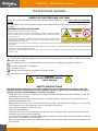
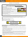
EXPLANATION OF SYMBOLS ON THE SILKSCREEN
The triangle containing a lightning symbol is used to indicate whenever your health is at risk (due to electro-
cution, for example).
An exclamation mark in a triangle indicates particular risks in handling or operating the appliance.
The unit complies with CE standards
For indoor use only
0.5m
Minimum distance between the appliance and other objects
Don’t stare into the beam
CAUTION
DO NOT OPEN THE HOUSING
SHOCK HAZARD
SAFETY INSTRUCTIONS
This unit contains high power laser devices internally. Do not open the laser housing, due to po-
tential exposure to unsafe levels of laser radiation. The laser power levels accessible if the unit is
opened, can cause instant blindness, skin burns and res.
• Please read these instructions carefully, they include important information about the installation, usage and
maintenance of this product.
• Please keep this User Guide for future reference. If you sell the unit to another user, be sure that he also re-
ceives this instruction booklet.
• Always make sure that you are connecting to the proper voltage, and that the line voltage you are connecting
to is not higher than that stated on the decal or rear panel of the xture.
• This product is intended for indoor use only!
• This unit must be earthed.
• To prevent risk of re or shock, do not expose xture to rain or moisture. Make sure there are no ammable
materials close to the unit while operating.
• The unit must be installed in a location with adequate ventilation, at least 20in (50cm) from adjacent surfaces.
Be sure that no ventilation slots are blocked.
• Always disconnect from power source before servicing or replacing fuse and be sure to replace with same fuse
size and type.

MANUAL - SCAN Laser Systems
3
www.ibiza-light.com
EN
• Secure xture to fastening device using a safety chain.
• Maximum ambient temperature (Ta) is 104° F (40°C). Do not operate the xture at temperatures higher than
this.
• In the event of a serious operating problem, stop using the unit immediately. Never try to repair the unit by
yourself. Repairs carried out by unskilled people can lead to damage or malfunction. Please contact the near
-
est authorized technical assistance centre. Always use the same type of spare parts.
• Don’t connect the device to a dimmer pack.
• Make sure the power cord is never crimped or damaged.
• Never disconnect the power cord by pulling or tugging on the cord.
• Don’t expose your eyes to the light source while it is on.
DISCONNECT DEVICE: Where the MAINS plug or an appliance coupler is used as the disconnect device, the
disconnect device shall remain readily operable.
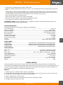
LASER EMISSION DATA
As measured under IEC measurement conditions for classication.
Laser Classication ............................................................................................................................ Class 3B
Green Laser Medium ....................................................................................................................DPSS 532nm
Red Laser Medium ...................................................................................................LD GaAIAs 638nm,typical
Blue Laser Medium .................................................................................................. LD InGaN 445nm, typical
Beam Diameter .................................................................................................................. <3mm at aperture
Divergence(each beam) ..................................................................................................................<1.3 mrad
Divergence(total light) .....................................................................................................................<1.3mrad
Transverse Beam Mode ......................................................................................................................... TEM00
Cooling ................................................................................................................................TEC & Fan Cooling
Scanning .............................................................................................................. High speed scanner 25kpps
LASER POWER
SCAN500RGB : ........................................................100mW-G-532nm+200mW-R-650nm+200mW-B-445nm
SCAN1100RGB: .......................................................200mW-G-532nm+300mW-R-638nm+600mW-B-445nm
SCAN2000 RGB: ....................................................500mW-G-532nm+500mW-R-638nm+1000mW-B-445nm
SCAN1100PINK: ..................................................................................... 500mW-R-638nm+600mW-B-445nm
SPECIFICATIONS
Mains Input: ....................................................................................................100-240V~ 50/60Hz, total 30W
Fuse: ............................................................................................................250V 2A slow blow (20mm glass)
Menu mode: .............................................................................Auto, music, DMX512, Master/slave, ILDA, IRC
Laser Classication: ........................................................................................................................... Class 3B
Laser Safety Standard:.......................................................................................................... EN60825-1:2014
Condition Temperature: .................................................................................................................. 10℃~40℃
DMX channels ..........................................................................................................................5 / 34 channels
Dimensions ......................................................................................................................246 x 211 x 105mm
Weight:....................................................................................................................................................3.5kg
INSTALLATION
The unit should be mounted via its screw holes on the bracket. Always ensure that the unit is rmly xed to
avoid vibration and slipping while operating. Always ensure that the structure to which you are attaching the unit
is secure and able to support a weight of 10 times of the unit’s weight. Also always use a safety cable that can
hold 12 times the weight of the unit when installing the xture.
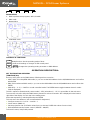
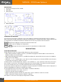
DMX512
1. Install the units in a suitable position (laying or appending).
2. Use standard XLR microphone cable chain your units together via the XLR connector on the rear of the units.
For longer cable runs we suggest a terminator at the last xture.
3. Assign a DMX address to each the unit.
4. Turn on all units’ power, the units begins reset, then the unit begins working.
5. Use DMX console to control your units.

MANUAL - SCAN Laser Systems
4
©Copyright LOTRONIC 2019
Console Light1 Light2 Light3
DESCRIPTION
1. Built-in performance programs, AUTO, SOUND
2. DMX mode
3. Master/Slave
4. ILDA DB25 mode
CONTROLS & FUNCTIONS
FUNC
Mode/Function: Set the operating mode of laser.
ENTER
: Conrms all settings or changes of LED control panel.
UP
/
DOWN
: Changes the operating mode, parameter or DMX address.
OPERATION DESCRIPTION:
SET THE FUNCTION OVERVIEW:
[FUNCTION] key:
At every short press on the FUNC button, following actions are active :
• INDR - DMX (5-CH simplied DMX mode) + you can set the DMX address via the UP/DOWN buttons and conrm
with ENTER
• DMX (34-CH advanced DMX mode) + you can set the DMX address via the UP/DOWN buttons and conrm with
ENTER
• INDR SE (1 – 2 – 3) = 3 AUTO or sound-controlled mode. The ENTER button toggles between these 2 modes
(SND is displayed)
The SE 1 sequence (beam/tunnels, waves mode) – SE 2 (animation 1) – SE 3 is accessible via the sub-menu.
To access the sub menu keep the FUNC button pressed for at least 3 seconds. SET is displayed on the bottom
right side of the display. You are now in the setting menu.
Select the sequence by selecting SE and press ENTER.
This sub-menu also allows to (not recommended for beginners!)
• Congure motors X & Y via dr – X and dr – Y
• Invert motors (SWAP XY)
• Set the projection size (X-SIZ with values from 0 to 100 and Y-SIZE with values from 0 to 100)
• Activate/deactivate the remote control ( REMOTE – ON/OFF)
To leave the menu, keep FUNC pressed.

MANUAL - SCAN Laser Systems
5
www.ibiza-light.com
EN
OVERVIEW OF PLAYBACK MODES:
There are multiple playback modes:
• Built-in Master mode: divided into three small playback modes.
>1: mixed playback: Drawing scenes from each sequence in taking turn playback (can be set by setting the
function).
>2: Sequence playback: only play a sequence. (This mode for the temporary mode, restart laser will not
automatically enter)
>3: Scene playback: only play a scene. This mode for the temporary mode, restart laser will not automati
-
cally enter)
• Slave mode: divided into the following two slave modes:
>1: DMX slave mode: Through the DMX signal line to follow the Master to play.
>2: ILDA slave mode: Accept the ILDA signal control from the Master or laser console.
• DMX playback mode:
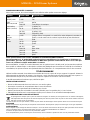
>1: Easy DMX mode: 5 channels
Note: Simple DMX mode takes the built-in scenes of the laser directly without any further settings.
CHANNEL DMX value DESCRIPTION
CH 1
On/o power
0 OFF
1-255 ON
CH2
Act auto/sound
0-127 AUTO
128-255 SOUND CONTROLLED
CH3
Gallery Menu
(scenes)
0-15 1 gallery (0)
16-31 2 gallery (16)
32-239 3 gallery (32)
240-255 40 gallery (240)
CH4
Scenes
0-255 Each value corresponds to a pattern, the value exceeds the number of pat-
terns, the system with the largest number instead
CH5
Colors
0-31 RGB
32-63 red
64-95 yellow
96-127 green
128-159 blueviolet
160-191 blue
191-223 purple
224-255 white
>2: Professional DMX mode: 34 channels
Order 1: Professional DMX mode is available to the experienced lighting engineers, who are pro
-
fessional in DMX control, as well as the laser pattern scanning principle , if not, pls use simple DMX
mode 4 channels
Order 2: DQF6 (the Bluetooth number) is a double-pattern laser system, and two patterns can be
scanned at the same time. The following description is distinguished by pattern A and pattern B.
For ease of view, the following points are shown in Table 1 and Table 2 respectively at the end of
the manual.

MANUAL - SCAN Laser Systems
6
©Copyright LOTRONIC 2019
• ILDA console mode: ILDA signal input, output ILDA eect.
Eects library: Each eect library is stored as a sequence on the motherboard, they are:
1. Geometric sequence (Gypsophalange filter);
2. Wedding theme sequence;
3. Christmas theme sequence;
4. Beam sequence (no filter);
5. Geometric sequence (Galaxy Nebula);
6. 3D sequence (3D filter);
7. Point circle sequence (dot circle filter);
8. Long virtual point sequence (long virtual point filter);
LED DISPLAY INSTRUCTION:
{INTR}{DMX}{APP}{SET}{SND}{SEL} for status identication.
• {INTR} Indicates that the xture is using the built-in eect. When the status ag is lit (INTR} alone, it is the
built-in eect play mode.
• {DMX} indicates that the xture is controlled by the DMX signal. The status ag is only bright (DMX) for the
standard DMX control mode
• {INTR} {DMX} is a simple DMX mode that calls the built-in scenario via DMX signals.
• {SET} indicates that the xture is in the system setup state.
• {SND} indicates that the motion of the pattern is controlled by the sound when the xture is in the built-in
mode.
• {SEL} In the set state, the indicator is lit to indicate that the current setting option is enabled.
{INTR} the state of the digital display section
• {AL} indicates the mix mode in the built-in mode (the scene play is extracted from each sequence).
• {P ###} Indicates the scene playback mode when the built-in mode is displayed. The displayed value is the
scene number.
• {SE ##} indicates the sequence playback mode when the built-in mode is displayed, and the displayed value
is the sequence number.
{DMX} the digital display part state.
{INTR} + {DMX}the digital display part state.
• {A ###} Indicates the DMX address code for the xture.
{SET} the digital display part state.
• {SE ##} Indicates whether the digital display sequence is selected when the mixed mode of the built-in mode
is used.
(Note: {SEL} status ag indicates whether the sequence is selected.)
• {DR- ||} indicates the X mirror setting.
• {DR- =} represents the Y mirror setting.
• {DR- = ||} represents XY oset.
• {x ###} represents the X projection amplitude, the digital part is the full scale percentage value
(Note: {SEL} can be adjusted through the button on the board).
• {y ###} denotes the Y projection amplitude (Note: same as above).
• {r0FF} Indicates whether or not the remote control function is turned o.
The virtual remote control of the mobile phone APP is the same as that described in the previous section.
Extinguished: After a few hours of no operation, the digital part of the display will go out (Note: the screen func
-
tion with the specic model, some models do not have the function)
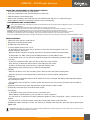
REMOTE CONTROL
Please operate the remote control within a distance of 6m and 30° between the remote and the appliance. Aim
the remote at the sensor. Remove all obstacles between the remote and the sensor.
The remote control might not work properly if the sensor is exposed to strong sunshine.
If the remote control doesn’t work properly, please check the batteries.

MANUAL - SCAN Laser Systems
7
www.ibiza-light.com
EN
INSTALLING THE BATTERIES IN THE REMOTE CONTROL
• Place the remote face down on a at surface.
• Push the compartment cover into the direction of the arrow.
• Slide the battery compartment open.
• Remove the old battery and install the new one (CR2032) with the plus (+) symbol facing up.
• Gently slide the battery compartment closed. It locks automatically.
RECOMMENDATIONS FOR BATTERIES
This symbol indicates that used batteries should not be disposed of with household waste but deposed correctly in accordance with
your local regulations..
Batteries shall not be exposed to excessive heat such as sunshine, re or the like.
When the internal batteries are not to be used, remove them to avoid damage caused by battery leakage or corrosion.
ATTENTION: Danger of explosion if battery is incorrectly placed. Only replace by the same or equivalent type.
WARNING :Do not swallow the battery. Danger of chemical burns. Keep new and old batteries out of the reach of children.
If the battery compartment doesn’t close properly, stop using the product and keep it out of the reach of children.
If you are in doubt whether the batteries have been swallowed or introduced into any other part of the body, contact immediately a doctor.
REMOTE CONTROL
• [INTR] key: Enter the mix mode built-in.
• [DMX] key: Professional DMX mode.
• [E-DMX] key: easy DMX mode.
• [1-9] key: digital number from 1 to 9
- In the built-in mix mode, press the [1-9] button to enter the scene playback mode. The
number entered is the scene
- When the built-in sequence is played, press the [1-9] button to select the serial number.
- In DMX mode or E- DMX mode, press the digital button to set the address code.
- In the setting mode, you can select the projection range when setting the projection angle.
• [+][-] key:
- In the scene playback mode, press this key to adjust the scene number.
- Press this key to adjust the serial number in the sequence play mode.
- In DMX or E- DMX mode, press this key to adjust the address code.
- When setting mode, press this key to adjust the setting item.
• [SET]key:
- When the system is not in the set state, press 5 times to enter the system setting state.
- When the system is in the setting state, press this key to exit the system setting state.
• [RGB] key:
- Press this key to toggle the pattern colour. When the colour is changed, the display will temporarily display
the currently set colour.
- This setting is set to temporary, and the system will return to the colour state (CLR) after the shut-down is
restarted.
• [SEQ] key: Press this key to enter the sequence playback mode in built-in mode.
• [B-Out] key: Press this key to turn o the laser output.
• [Sound] key:
- In the built-in mode, press this key to set or cancel the voice.
- When setting a mixed sequence, you can select or cancel a sequence.
- You can select or cancel the mirror when setting the graphic X mirror, the graphic Y mirror, and the XY for the
graphic.
- You can select or cancel the remote control when setting the remote control function.
• [ENTER] key: When entering a number, the value to be entered is less than 100, press this key to speed up the
digital input.
IMPORTANT NOTE: Electric products must not be put into household waste. Please bring them to a recycling centre. Ask your local au-
thorities or your dealer about the way to proceed.

MANUAL - SCAN Laser Systems
8
©Copyright LOTRONIC 2019
MANUEL D’UTILISATION
LASER A USAGE EXCLUSIVEMENT PROFESSIONNEL
Ce laser est conforme aux normes EN60825-1:2014, il est à usage exclusivement professionnel. Son
installation et utilisation doit être eectué exclusivement par un technicien compétent et formé aux risques
spéciques des lasers.
RAPPEL DES PRECAUTIONS DE SECURITE
WARNING
LASER
3B
AVOID EXPOSURE TO BEAM
EXPOSITION AU FAISCEAU DANGEREUSE
Les appareils à lasers de classe 3 et 4, sont utilisables exclusivement en plein air
A l’intérieur de la zone réservée au public, aucun « tir laser « n’est admis en direction
du public, quelle que soit la classe du laser, sauf si un périmètre d’exclusion du public
de 5 mètres de rayon, matérialisé, est mis en place.
La zone dite « zone réservée au public « est dénie par l’espace situé jusqu’à 3 mètres
au-dessus de la surface occupée par le public et sur une bande de 2, 5 mètres autour
de cette dernière. La zone réservée au public est matérialisée au sol.
Dans la zone réservée au public, seul est admis un rayonnement par balayage eectué dans les conditions xées par le rapport technique
international sur la sécurité des appareils à laser
L’appareil à laser est hors de portée du public et au minimum à 3 mètres au-dessus du sol accessible au public ou protégé par un périmètre
de sécurité de 5 mètres de rayon.
L’appareil laser doit être xé/posé de telle manière qu’il ne puisse pas être déplacé sous l’eet de perturbations telles que des mouvements
de foule, des vibrations ou des rafales de vent.
EXPLICATION DES SYMBOLES
L’éclair dans le triangle attire l’attention sur un danger physique (due à une électrocution p.ex.).
Le point d’exclamation dans le triangle indique un risque dans la manipulation ou l’utilisation de l’appareil.
En conformité avec les exigences de la norme CE
Utilisation uniquement à l’intérieur
0.5m
Distance minimum entre l’appareil et d’autres objets
Ne pas regarder directement dans le rayon lumineux
CONSIGNES DE SÉCURITÉ
Cet appareil contient un laser de haute puissance. Ne pas ouvrir le boîtier pour éviter des exposi-
tions dangereuses au laser. Le laser peut provoquer immédiatement de la cécité, des brulûres de la
peau et des incendies.
• Lisez attentivement ce manuel qui contient des informations importantes sur l’installation, l’utilisation et l’en-
tretien de cet appareil.
• Conservez le manuel pour référence ultérieure. Si l’appareil change un jour de propriétaire, assurez-vous que le
nouvel utilisateur est en possession du manuel.
• Assurez-vous que la tension secteur convient à cet appareil et qu’elle ne dépasse pas la tension d’alimentation
indiqué sur la plaque signalétique de l’appareil.
• Uniquement pour utilisation à l’intérieur!
• An d’éviter tout risque d’incendie ou de choc électrique, ne pas exposer cet appareil à la pluie ou à l’humidité.
Assurez-vous qu’aucun objet inammable ne se trouve à proximité de l’appareil pendant son fonctionnement.
• Installez l’appareil à un endroit bien ventilé à une distance minimum de 50cm de toute surface. Assurez-vous
que les fentes de ventilation ne sont pas bloquées.
• Débranchez l’appareil du secteur avant toute manipulation ou entretien. Lorsque vous remplacez le fusible,
utilisez uniquement un fusible qui présente exactement les mêmes caractéristiques que l’ancien.
• La température ambiante ne doit pas dépasser 40°C. Ne pas faire fonctionner l’appareil à des températures
supérieures.
ATTENTION
NE PAS OUVRIR LE BOITIER
RISQUE DE CHOC ELECTRIQUE

MANUAL - SCAN Laser Systems
9
www.ibiza-light.com
FR
• En cas de dysfonctionnement, arrêtez immédiatement l’appareil. N’essayez jamais de réparer l’appareil par
vous-même. Une réparation mal faite peut entraîner des dommages et des dysfonctionnements. Contactez un
service technique agréé. Utilisez uniquement des pièces détachées identiques aux pièces d’origine.
• Ne pas brancher l’appareil sur un variateur.
• Assurez-vous que le cordon d’alimentation n’est jamais écrasé ni endommagé.
• Ne pas exposer vos yeux à la source lumineuse.
DISPOSITIF DE COUPURE DU SECTEUR: Lorsque le cordon d’alimentation ou un coupleur d’appareil est utilisé
comme dispositif de déconnexion, ce dispositif doit rester facilement accessible;
Si un interrupteur omnipolaire est utilisé comme dispositif de déconnexion, l’emplacement sur l’appareil et la
fonction de l’interrupteur doit être décrite, et le commutateur doit rester facilement accessible
INFORMATIONS SUR LES ÉMISSIONS DU RAYON LASER
Mesuré sous des conditions IEC pour classication.
Classication Laser ...........................................................................................................................Classe 3B
Laser vert .....................................................................................................................................DPSS 532nm
Laser rouge ........................................................................................................... LD GaAIAs 638nm, typique
Laser Bleu .............................................................................................................. LD InGaN 445nm, typique
Diamètre du rayon .............................................................................................................. <3mm à la sortie
Divergence (chaque rayon).............................................................................................................<1.3 mrad
Divergence (total) ............................................................................................................................<1.3mrad
Transverse Beam Mode ......................................................................................................................... TEM00
Refroidissement ...................................................................................................................TEC & ventilateur
Balayage .......................................................................................................... Scanner haute vitesse 25kpps
PUISSANCE LASER
SCAN500RGB : ........................................................100mW-G-532nm+200mW-R-650nm+200mW-B-445nm
SCAN1100RGB: .......................................................200mW-G-532nm+300mW-R-638nm+600mW-B-445nm
SCAN2000 RGB: ....................................................500mW-G-532nm+500mW-R-638nm+1000mW-B-445nm
SCAN1100PINK: ..................................................................................... 500mW-R-638nm+600mW-B-445nm
CARACTÉRISTIQUES TECHNIQUES
Alimentation ...................................................................................................................100-240V~, 50/60Hz
Fusible ...................................................................................................................250V 2A lent (verre 20mm)
Modes: ..............................................................Auto, musique, DMX512, Master/slave, ILDA, télécommande
Classication Laser: ..........................................................................................................................Classe 3B
Norme de sécurité laser: ....................................................................................................... EN60825-1:2014
Température ambiante: .................................................................................................................. 10℃~40℃
Canaux DMX .............................................................................................................................. 5 / 34 canaux
Dimensions ......................................................................................................................246 x 211 x 105mm
Poids: ......................................................................................................................................................3.5kg
MONTAGE
Fixez l’appareil sur l’étrier au moyen des trous de vis. Assurez-vous que l’appareil est solidement xé an d’évi-
ter des vibrations et des mouvements pendant le fonctionnement. Vériez que le support sur lequel vous allez
installer l’appareil est solide et capable de supporter au moins 10 fois le poids de l’appareil. Lors de l’installation
utilisez toujours un câble de sécurité supplémentaire qui peut porter 12 fois le poids le d’appareil.
DMX512
1. Installez les appareils dans une position appropriée (couché ou suspendu).
2. Reliez les appareils avec un câble XLR standard de microphone par les connecteurs XLR au dos. En cas de
chaînes plus longues, nous recommandons l’emploi d’une résistance de n de ligne sur le dernier appareil.
3. Aectez une adresse DMX à chaque appareil.
4. Mettez tous les appareils sous tension. Ils eectuent d’abord un reset et sont ensuite opérationnels.
5. Commandez les appareils avec une console DMX.
Console Light1 Light2 Light3

MANUAL - SCAN Laser Systems
10
©Copyright LOTRONIC 2019
DESCRIPTION
1. Programmes intégrés, AUTO, SOUND
2. Mode DMX
3. Maître/Esclave
4. Mode ILDA DB25
CONTROLES & FONCTIONS
Lors de la mise sous tension, l’acheur à LED au dos indique le mode de fonctionnement actuel ou l’adresse
DMX. Il permet de changer facilement le mode de fonctionnement ou l’adresse DMX. Après chaque remise à zéro
ou sauvegarde, les nouvelles informations s’achent sur l’écran à la prochaine mise sous tension.
FUNC
Mode/Fonction: Réglage du mode de fonctionnement du laser.
ENTER
: Conrme tous les réglages et changements.
UP
/
DOWN
: Change de mode de fonctionnement, les paramètres ou l’adresse DMX.
DESCRIPTION:
FONCTION DE RÉGLAGE:
Chaque pression courte sur le bouton FUNC eectue les actions suivantes :
• INDR - DMX (mode dmx simplié 5 canaux) + possibilité de réglage de l’adresse DMX via les boutons UP /
DOWN et valider avec bouton ENTER
• DMX (mode DMX étendu 34 canaux) + possibilité de réglage de l’adresse DMX via les boutons UP / DOWN et
valider avec bouton ENTER
• INDR SE (1 – 2 – 3) = 3 modes Auto ou son. Dans ce mode en appuyant sur le bouton ENTER on bascule entre
le mode auto et le mode son (SND sur l’écran)
La séquence SE 1 (mode beam/tunnels, vagues) – SE 2 (animation 1) – SE 3 peut être choisie vie le sous menu.
Pour accèder au sous menu, il faut appuyer longuement sur le bouton FUNC (3 secondes) le mot SET apparait
alors en bas à droite de l’écran, vous êtes maintenant dans le menu d’ajustement.
On peut alors choisir la séquence en se mettant sur SE et en appuyant sur ENTER. Ensuite choisir la séquence en
utilisant UP/DOWN puis ré-appuyer sur ENTER pour valider
On peut également via ce sous menu ( déconseiller à l’utilisateur débutant) :
• Paramétrer les moteurs X et Y via dr – X et dr – Y
• Inverser le sens des moteurs (SWAP XY)
• Régler la taille de projection (X-SIZE avec valeur de 0 à 100 et Y-SIZE avec valeur de 0 à 100)
• Activer / désactiver la télécommande ( REMOTE – ON/OFF)
Pour quitter ce sous menu il faut appuyer longuement sur FUNC.

MANUAL - SCAN Laser Systems
11
www.ibiza-light.com
FR
MODE DMX SIMPLIFIÉ À 5 CANAUX
Note: Dans ce mode, les scènes intégrées sont utilisées telles quelles sont autre réglage.
CANAL Valeur DMX DESCRIPTION
CH 1
On/o power
0 OFF
1-255 ON
CH2
Act auto/sound
0-127 AUTO
128-255 Contrôlé par la musique
CH3 Gallery
Menu (scenes)
0-15 1 gallery (0)
16-31 2 gallery (16)
32-239 3 gallery (32)
240-255 40 gallery (240)
CH4
Scenes
0-255 Chaque valeur correspond à un motif. Si la valeur dépasse le nombre de
motifs, c’est le motif avec le nombre le plus élevé qui est sélectionné
CH5
colors
0-31 RGB
32-63 Rouge
64-95 Jaune
96-127 Vert
128-159 Bleu-violet
160-191 Bleu
191-223 Pourpre
224-255 Blanc
Mode professionnel à 34 Canaux: RÉSERVÉ AUX PROFESSIONNELS AVERTIS
Recommandation 1: le mode DMX professionnel est conseillé pour les ingénieurs en éclairage ex
-
périmentés, qui sont des professionnels du DMX ainsi que des numérisations laser. Si ce n’est pas
votre cas, utilisez le simple mode DMX à 5 canaux.
Recommandation 2: DQF6 (le numéro Bluetooth) est un système laser à double motif, qui permet de numériser
deux motifs en même temps. La description suivante est distinguée par le motif A et le motif B. Pour faciliter la
visualisation, les points suivants sont présentés dans les Tableaux 1 et 2 respectivement à la n de ce manuel.
TÉLÉCOMMANDE
Utilisez la télécommande à une distance maximale de 6m et un rayon de 30° par rapport à l’appareil. Pointez la
télécommande en direction du capteur. Il ne doit pas y avoir d’obstacle entre la télécommande et le capteur. La
télécommande risque de ne pas fonctionner lorsque le capteur est soumis à une forte lumière.
Si la télécommande ne fonctionne pas, vériez les piles
INSTALLATION DES PILES
• Placez la télécommande face vers le bas sur une surface plane.
• Poussez le couvercle du compartiment dans le sens de la èche.
• Faites glisser le compartiment de la batterie pour l’ouvrir.
• Retirez l’ancienne pile et installez la nouvelle (CR2032) avec le symbole plus (+) vers le haut.
• Faites glisser doucement le compartiment à piles pour le fermer. Il se verrouille automatiquement.
RECOMMANDATIONS POUR LES BATTERIES
Ce pictogramme indique que les piles et batteries usagées ne doivent pas être jetées avec les ordures ménagères,
mais déposées dans des points de collecte séparés pour être recyclées. Tenir les piles à l’abri d’une chaleur excessive
telle que le soleil, le feu ou similaires.
Lorsque les piles ne sont pas utilisées, retirez-les pour éviter les dommages causés par des fuites ou la corrosion de la pile.
ATTENTION
Danger d’explosion si la pile n’est pas remplacée correctement. Ne remplacer que par le même type ou un type équivalent.
AVERTISSEMENT
Ne pas ingérer la pile. Danger de brûlure chimique. En cas de doute concernant le fait que les piles pourraient avoir été ava-
lées ou introduites dans une partie quelconque du corps, consulter immédiatement un médecin.
Conserver les piles neuves et usées hors de portée des enfants.
Si le compartiment à pile ne se ferme pas correctement, cesser d’utiliser le produit et tenir hors de portée des enfants.

MANUAL - SCAN Laser Systems
12
©Copyright LOTRONIC 2019
>3: MODE ILDA: ILDA SIGNAL INPUT, OUTPUT ILDA EFFECT.
* Bibliothèque d’eets: Chaque librairie est sauvegardé en tant que séquence sur la carte-mère:
1: Séquences géométriques (Gypsophalange lter);
2: Thème Mariage
3: Thème Noël
4: Rayons (sans ltre)
5: Séquence géométrique (Galaxy Nebula);
6: Séquences 3D (3D lter);
7: Séquences points- cercles (dot circle lter);
8: Longue séquence point virtuel (long virtual point lter);
LED DISPLAY:
{INTR}{DMX}{APP}{SET}{SND}{SEL} IDENTIFIE L’ÉTAT DE FONCTIONNEMENT.
• {INTR} signie que l’appareil utilise un eet intégré. Lorsque cet indicateur est allumé seul, l’appareil est en
mode de lecture de l’eet intégré.
• {DMX} signie que l’appareil est commandé par DMX. Cet indicateur ne s’allume qu’en mode DMX standard.
• {INTR} {DMX} est un mode DMX simple qui fait appel au scénario intégré via les signaux DMX.
• {SET} signie que l’appareil est en mode paramétrage.
• {SND} indique que le mouvement du motif est contrôlé par le son lorsque l’appareil est en mode audio.
• {SEL} En mode paramétrage, cet indicateur montre l’option active.
{INTR}
• {AL} indique un mode combiné (une scène est extraite de chaque séquence)
• {P ###} indique le numéro de la scène en cours de lecture.
• {SE ##} indique le numéro de la séquence en lecture.
{DMX}
{INTR} + {DMX}SONT AFFICHÉS.
• {A ###} indique l’adresse DMX de l’appareil.
{SET}
• {SE ##} indique la séquence en mode combiné
(Note: {SEL} un indicateur montre si la séquence est activée.)
• {DR- ||}position du miroir X.
• {DR- =} Position du miroir Y.
• {DR- = ||} oset XY.
• {x ###} représente l’amplitude de projection X. Le chire est le pourcentage par rapport au maximum
(Note: {SEL} peut être réglé à l’aide du bouton sur la carte-mère.).
• {y ###} représente l’amplitude de projection Y (Note: comme ci-dessus).
• {r0FF} indique si la fonction télécommande est activée ou non.
• La télécommande virtuelle de l’application mobile est la même que dans la section précédente.
* Éteint: Après quelques heures d’inactivité, la partie numérique de l’acheur s’éteint.

MANUAL - SCAN Laser Systems
13
www.ibiza-light.com
FR
TÉLÉCOMMANDE
• [INTR] : Mode automatique intégré.
• [DMX] : DMX professionnel.
• [E-DMX] : DMX simplié.
• [1-9] : pave numérique
- En mode INTR, appuyez sur une touche [1-9] pour aller en mode de lecture d’une scène.
Le chire entré correspond à une scène
- En mode DMX ou E- DMX, appuyez sur les touches pour entrer l’adresse DMX.
- En mode de réglage vous pouvez sélectionner la distance de projection lors du réglage de
l’angle de projection.
• [+][-]:
- En mode lecture de scène, appuyez pour ajuster le numéro de scène.
- En mode DMX ou E- DMX appuyez pour ajuster l’adresse DMX.
• [SET]:
- Si l’appareil n’est pas en mode de réglage, appuyez 5 fois pour entrer en mode de réglage
- Lorsque l’appareil est en mode de réglage, appuyez pour quitter le mode de réglage.
• [RGB]:
-Sélection de la couleur
• [SEQ]: En mode automatique, entrer en mode lecture d’une séquence.
• [B-Out]: Éteint le laser
• [Sound]:
- En mode auto, appuyez pour régler ou annuler la sensibilité audio.
- Lors du réglage d’une séquence mixte, vous pouvez sélectionner ou annuler une séquence.
- Vous pouvez sélectionner ou annuler un miroir lorsque vous réglez le miroir graphique X, Y ou XY.
- Vous pouvez activer ou déactiver la télécommande lorsque vous en mode réglage de la télécommande.
• [ENTER]: Lorsque vous entrez un chire et la valeur à entrer est inférieure à 100, appuyez pour accélérer.
Ce symbole signie que cet appareil ne doit être mis aux déchets ménagers dans aucun pays de la Communauté européenne an d’éviter de
nuire à l’environnement et à la santé humaine. Il convient d’en disposer d’une manière responsable an de promouvoir la réutilisation
des matériaux. Pour retourner votre appareil usagé, merci d’utiliser les systèmes de retours et de ramassage mis en place ou de contac-
ter votre revendeur chez qui vous avez acheté l’appareil. Ils peuvent reprendre cet appareil pour un recyclage écologique.

MANUAL - SCAN Laser Systems
14
©Copyright LOTRONIC 2019
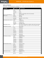
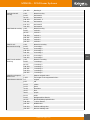
TABLE 1 (PATTERN A):
Note: Table 1: CH1-Ch17, pattern A’s channel function, except for special instructions, only control the pattern A,
pattern B is not controlled by these 17 channels:
CHANNEL DMX value DESCRIPTION
CH 1 On/o power 0 OFF
1-99 ON
100-199 AUTO
200-254 Retain
255 Pattern A closed light, pattern B output light
CH2 Out of bounds and
pattern size
0-49 Out of bounds
50-99 Reentry
100-149 Blanking
150-199 Blanking+ pattern enlarge
200-255 Retain
CH3 Gallery Menu (sences) 0-15 1 gallery (0)
16-31 2 gallery (16)
32-239 3 gallery (32)
240-255 40 gallery (240)
CH4 Gallery choose 0-255 Each value corresponds to a pattern, when the value exceeds
the number of patterns, the system uses the largest number
CH5 Patterns zooming 0 No zooming
1-31 Zooming 1
32-63 Zooming 2
64-95 Zooming3
96-127 Zooming4
128-159 Zooming 5
160-191 Zooming 6
192-223 Zooming 7
224-255 Zooming8
CH6 Patterns rotating 0-63 Manual rotating
64-95 Rotating 1
96-127 Rotating 2
128-159 Rotating 3
160-191 Rotating 4
192-223 Rotating 5
224-255 Rotating 6
CH7 Horizontal moving 0-63 Manual moving
64-95 Horizontal 1
96-127 Horizontal 2
128-159 Horizontal 3
160-191 Horizontal 4
192-223 Horizontal 5
224-255 Horizontal 6
CH8 Vertical moving 0-63 Manual moving
64-95 vertical 1
96-127 vertical 2

MANUAL - SCAN Laser Systems
15
www.ibiza-light.com
EN
128-159 vertical 3
160-191 vertical 4
192-223 vertical 5
224-255 vertical 6
CH9 X axis
Horizontal zooming
0-63 Manual X zooming
64-95 X zooming 1
96-127 X zooming 2
128-159 X zooming 3
160-191 X zooming 4
192-223 X zooming 5
224-255 X zooming 6
CH10 Y axis vertical zoom-
ing
0-63 Manual Y zooming
64-95 Y zooming 1
96-127 Y zooming 2
128-159 Y zooming 3
160-191 Y zooming 4
192-223 Y zooming 5
224-255 Y zooming 6
CH11 Force Segmentation
Color
0 Patterns original colours
1-255 The length of the segmented colours
CH12 Patterns discolor 0-7 Original
8-15 Red
16-23 Yellow
24-31 Green
32-39 blue-violet
40-47 Blue
48-55 Purple
56-63 White
64-95 Red/green/blue discolour
96-127 Blue violet/blue/purple discolour
128-159 7 colours discolour
160-191 RGB discolour
192-223 Positive walking colour
224-255 Reverse walking colour
CH13 Node and blanking
control
0-63 Normal blanking control
64-127 Patterns without blanking, yback line banking
128-159 Patterns and line without blanking
160-255 Retain
CH14 The auxiliary function
of the drawing control (used
in conjunction with CH15)
0-63(CH15) Manual gradually drawing
64-127/160-
191(CH15)
The moving time of the pattern drawing gradually
192-255 The number of nodes that are drawn
CH15 Progressive control
[CH15 must be used in con-
junction with CH14]
0-31 Forward hand-drawn gradually
32-63 Reverse manual drawing
64-95 Extended drawing
96-127 Contraction drawing

MANUAL - SCAN Laser Systems
16
©Copyright LOTRONIC 2019
128-159 Both ends are zoomed at the same time
160-191 Head and tail were zooming
192-223 Walking drawing
224-255 Turn over drawing
CH16 Auxiliary control of
twist deformation eect
channel
0-255 0-255, the greater the value, the smaller the distortion. [Note:
CH16 can control the degree of twist of the twist eect when
zooming, rotating, moving, and twisting eects]
CH17 Grating selection and
projection amplitude control
0-255 [0-19,grating 1] [20-39,grating 2].....[220-239,grating 12]
[240-255,grating 13] Note: In each paragraph, the larger the
value, the smaller the projection range
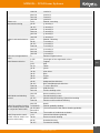
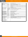
TABLE 2 (PATTERN B):
Note: Table 2: CH18-CH34, pattern B’s channel function, except for special instructions, only control the pattern B,
pattern A is not controlled by these 17 channels.
In order to simplify the operation, the functions correspond to pattern A, only special green parts are dierent.
CHANNEL DMX value DESCRIPTION
CH 18 On/o power 0 o working
1-99 Act auto
100-199 Act sound
200-254 retain
255 Pattern A closed light, pattern B output light
CH19 Out of bounds
and pattern size
0-49 Out of bounds
50-99 Re-entry
100-149 Blanking
150-255 Retain
CH20 The distribution
angle of each unit of
the array
0-99 the smaller the value of the segment, the larger the angular distribution
of each unit, the gap is a positive gap
100-199 the smaller the value of the segment, the larger the angle distribution of
each unit, the gap is the negative gap
200-255 retain
CH21 Gallery choose 0-255 Each value corresponds to a pattern, when the value exceeds the num
-
ber of patterns, the system uses the largest number
CH22 Patterns zoom
-
ing
0 No zooming
1-31 Zooming 1
32-63 Zooming 2
64-95 Zooming3
96-127 Zooming4
128-159 Zooming 5
160-191 Zooming 6
192-223 Zooming 7
224-255 Zooming8
CH23 Patterns rotating 0-63 Manual rotating
64-95 Rotating 1
96-127 Rotating 2
128-159 Rotating 3
160-191 Rotating 4
192-223 Rotating 5

MANUAL - SCAN Laser Systems
17
www.ibiza-light.com
EN
224-255 Rotating 6
CH24 Horizontal
moving
0-63 Manual moving
64-95 Horizontal 1
96-127 Horizontal 2
128-159 Horizontal 3
160-191 Horizontal 4
192-223 Horizontal 5
224-255 Horizontal 6
CH25 Vertical moving 0-63 Manual moving
64-95 vertical 1
96-127 vertical 2
128-159 vertical 3
160-191 vertical 4
192-223 vertical 5
224-255 vertical 6
CH26 X axis
Horizontal zooming
0-63 Manual X zooming
64-95 X zooming 1
96-127 X zooming 2
128-159 X zooming 3
160-191 X zooming 4
192-223 X zooming 5
224-255 X zooming 6
CH27 Y axis vertical
zooming
0-63 Manual Y zooming
64-95 Y zooming 1
96-127 Y zooming 2
128-159 Y zooming 3
160-191 Y zooming 4
192-223 Y zooming 5
224-255 Y zooming 6
CH28 Force Segmen
-
tation Color
0 Patterns original colors
1-255 The length of the segmented colors
CH29 Patterns discolor 0-7 original
8-15 red
16-23 yellow
24-31 green
32-39 blueviolut
40-47 blue
48-55 purple
56-63 white
64-95 Red/green/blue discolor
96-127 Blueviolut/blue/purple discolor
128-159 7 colors discolor
160-191 RGB discolor
192-223 Positive walking color
224-255 Reverse walking color

MANUAL - SCAN Laser Systems
18
©Copyright LOTRONIC 2019
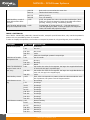
CH30 Node and blank-
ing control
Array control
0-63 Normal blanking control
64-127 Patterns without blanking, yback line banking
128-159 Patterns and line without blanking
160-191 Pattern A anchored in an array pattern of pattern B, pattern color setting
same with A
192-255 Pattern A anchored in an array pattern of pattern B, pattern color setting
same with B
CH31 The auxiliary
function of the draw
-
ing control (used
in conjunction with
CH32)
0-63(CH32) Manual gradually drawing
64-127/160-
191(CH32)
The moving time of the pattern drawing gradually
192-255
(CH32)
The number of nodes that are drawn
CH32 Progressive
control [CH32 must
be used in conjunc
-
tion with CH31];
When the pattern A is
voice-activated, the
CH32 action will also
become a voice-acti
-
vated state
0-31 Forward hand-drawn gradually
32-63 Reverse manual drawing
64-95 Extended drawing
96-127 Contraction drawing
128-159 Both ends are zoomed at the same time
160-191 Head and tail were zooming
192-223 Walking drawing
224-255 Turn over drawing
CH33 Auxiliary control
of twist deformation
eect channel
0-255 0-255, the greater the value, the smaller the distortion. [Note: CH33 can
control the degree of twist of the twist eect when zooming, rotating,
moving, and twisting eects]
CH34 projection am
-
plitude control
Note: In each para
-
graph, the larger the
value, the smaller the
projection range
0-255 (0-19),(20-39).....(220-239) , (240-239),(240-255)

MANUAL - SCAN Laser Systems
19
www.ibiza-light.com
EN
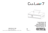
VIEW THE PRODUCTS ON OUR WEBSITE
SCAN500RGB
SCAN2000RGB
SCAN1100RGB
SCAN1100PINK

©Copyright LOTRONIC 2019
Imported from China by LOTRONIC S.A.
Avenue Zénobe Gramme 9
B-1480 Saintes
www.ibiza-light.com
-
 1
1
-
 2
2
-
 3
3
-
 4
4
-
 5
5
-
 6
6
-
 7
7
-
 8
8
-
 9
9
-
 10
10
-
 11
11
-
 12
12
-
 13
13
-
 14
14
-
 15
15
-
 16
16
-
 17
17
-
 18
18
-
 19
19
-
 20
20


Ibiza Light SCAN500RGB Le manuel du propriétaire
- Catégorie
- Stroboscopes
- Taper
- Le manuel du propriétaire
- Ce manuel convient également à
dans d''autres langues
Documents connexes

Autres documents
-
 JBSYSTEMS CLUB LASER 7 Le manuel du propriétaire
-
 afx light DMX512-PRO Le manuel du propriétaire
-
Nicols X-line 1500 RGB IP Manuel utilisateur
-
Briteq BT-LASER1500 RGB Le manuel du propriétaire
-
-
 JBSYSTEMS CLUB LASER 7 MK2 Le manuel du propriétaire
-
-
-
-
Evolite M2000 Manuel utilisateur


