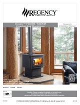
United States Stove Colonial TR004 Le manuel du propriétaire
- Catégorie
- Cheminées
- Taper
- Le manuel du propriétaire
Ce manuel convient également à

CAUTION!
Please read this entire manual before you
install and use your new heater. Failure to
follow instructions may result in property
damage, bodily injury, or even death.
U.S. STOVE
227 Industrial Park Road
South Pittsburg, TN 37380, USA
1-800-750-2723
SAVE THESE INSTRUCTIONS
THIS MANUAL WILL HELP YOU TO OBTAIN EFFICIENT, DEPENDABLE SERVICE FROM THE HEATER, AND ENABLE YOU
TO ORDER REPAIR PARTS CORRECTLY. KEEP IN A SAFE PLACE FOR FUTURE REFERENCE.
852137E-1203H
MODEL: TR004
Fireplace Insert
Masonry Fireplace Insert or Zero-Clearance (metal) Fireplace Insert
SAFETY NOTICE:
If this heater is not properly installed, a house re
may result. For your safety, follow the installation
instructions. Contact local building or re ofcials
about restrictions and installation in your area.
DO NOT use this appliance in a mobile
home, manufactured home, trailer, or tent.
U.S. Environmental Protection Agency
Certied to comply with 2015 particulate
emissions standards.
Certied to: UL1482 and Certied to: ULC S628
Owner’s Operation and Instruction Manual

2
The instructions pertaining to the installation of your wood stove comply with UL-1482 and ULC-S628 standards. This
manual describes the installation and operation of the Vogelzang, TR004 wood heater. This heater meets the 2015
U.S. Environmental Protection Agency’s crib wood emission limits for wood heaters sold after May 15, 2015. Under
specic test conditions this heater has been shown to deliver heat at rates ranging from 11,805 to 27,252 Btu/hr.
Note: The BTU ratings mentioned above are based on the EPA test protocol burning dimensional Douglas Fir lumber.
Our advertised BTU’s are based on the rst hour of operation at high burn rate burning cordwood.
1. The installation of this appliance must comply with
your local building code rulings.
2. DO NOT INSTALL THIS APPLIANCE IN A MOBILE
HOME, MANUFACTURED HOME, TRAILER OR TENT
(NO EXCEPTIONS PER HUD FEDERAL STANDARD: 24
CFR CH.XX).
3. Verify that the appliance is properly installed
before ring for the rst time. This appliance should
be installed by a qualied installer to insure a
correct and safe installation. NEVER use temporary
or makeshift compromises during the installation.
4. If there are any missing or damaged components of
the appliance, contact your dealer immediately.
DO NOT operate this appliance with missing or
damaged parts.
5. WARNING: RISK OF FIRE. Observe the minimum
clearances to combustibles stated in this manual
and on the labels attached to the appliance. DO
NOT store wood, any type of ammable vapors
or liquids, place furniture, rugs, carpet, clothing or
other combustible objects within the clearance
area.
6. Do Not connect this appliance to any air
distribution duct or system.
7. Do not tamper with the combustion air control of
this unit beyond normal adjustment range.
8. Provide adequate combustion air to the room
where the appliance is installed. Restricting
combustion air will result in a lazy re which causes
soot or creosote buildup and greatly reduces
efciency.
9. Always connect this appliance to a chimney
that vents to the outside. Never vent into another
room, crawl space, attic, or inside a building. Do
not connect this unit to a chimney ue serving
another appliance.
10. DO NOT connect a wood burning appliance
to an aluminum Type B gas vent. This is not safe.
Use approved masonry or a UL 103 HT (U.S.) Listed
Residential Type and Building Heating Appliance
Chimney. Use a 6” diameter chimney, that is high
enough to create sufcient draft.
11. Be sure your chimney is safely constructed and
in good repair. Have the chimney inspected by
the re department or a qualied inspector. Your
insurance company should be able to recommend
a qualied inspector.
12. Creosote or soot may build up in the chimney
liner or chimney and cause a house/building re.
Inspect the chimney and chimney liner twice
monthly during the heating season and clean if
necessary.
13. In the event of a chimney re, turn the air controls
to the closed position, leave the building and call
the re department immediately!
14. To prevent injury, do not allow anyone to use
this appliance that is not familiar with its correct
operation. Do not operate this appliance while
under the inuence of alcohol or drugs.
15. Caution: Hot Surfaces. Keep Children Away. Do
not touch while in operation. Contact may cause
skin burns.
16. Children should be alerted to the hazards from high
surface temperatures. Never leave small children
unsupervised when they are in the same room
as the appliance during operation. To prevent
burns, always wear protective clothing, leather
hearth gloves, and eye protection when refueling
or re maintenance. Always be aware of heated
surfaces. Heat radiating from the appliance
can potentially discolor, melt, or even ignite
combustible materials. KEEP ALL COMBUSTIBLE
MATERIALS WELL AWAY FROM THE HEATER!
17. WARNING: RISK OF FIRE. Keep the feed door tightly
closed at all times except when tending the re.
18. DO NOT overre this appliance. Overring will occur
if the feed door is left open during operation. If any
part of the appliance glows, you are overring.
Adjust air controls to a lower setting to slow down
the re.
19. DO NOT Elevate the re! Build the re directly on
the rebrick. This appliance has not been tested
with the use of any means to elevate the re and
it should not be attempted.
20. Ashes should not be allowed to accumulate more
than two to three inches in the rebox.
21. The paint on your appliance is durable but will not
stand rough handling or abuse. The paint used
may give off smoke and/or an odor during the rst
few res. This will occur until the paint has cured.
Animals / people with lung problems should not be
present during the curing process. Build small res
at rst to help this process and open windows and
doors as needed to clear the smoke and odor. If
the appliance is overred, the paint will discolor.
When installing your unit, take care in handling.
Clean with soap and water when the appliance is
not in use. Do not use any acids, abrasive cleaners
or scouring soap as these solvents wear and dull
the nish.
Safety Instructions

3
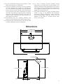
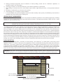
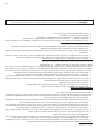
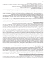
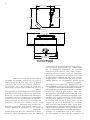
Dimensions
26 11/32 [669.0 mm]
13 5/32 [334.5 mm]
27 1/32 [686.6 mm]
21 13/16 [554.0 mm]
22 1/4 [565.0 mm]
15 1/2 [394.0 mm]4 11/16 [118.8 mm]
44 7/32 [1123.0 mm]
6.00 INSIDE
22. DO NOT ROUTE THE blower power SUPPLY CORD
NEAR OR ACROSS HOT SURFACES!
23. Canada Installations requires that this replace
must be installed with a continuous chimney liner
of 6 inch diameter extending from the replace
insert to the top of the chimney. The chimney liner
must conform to the Class 3 requirements of CAN/
ULC-S635, Standard for Lining Systems for Existing
Masonry or Factory-Built Chimneys and Vents, or
CAN/ULC-S640, Standard for Lining Systems for
New Masonry Chimneys.
24. Permanently seal any opening between the
masonry of the replace and the facing masonry.
25. Fireplace insert surround panels may be removed
to inspect replace insert and replace.
26. U.S. Stove Company requires installing smoke
detectors in the same room as the heater if not
already installed. Smoke expelled from the unit by
either paint curing, opening the fuel loading door,
or a negative pressure inside the home could
trigger the smoke detectors.
27. For further information on using your heater safely,
obtain a copy of the National Fire Protection
Association (NFPA) publication “Using Coal and
Wood Stoves Safely” NFPA No. HS-10-1978. The
address of the NFPA is 1 Battery March Park,
Quincy, MA. 02269.

4
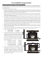
Pre-Installation Requirements
FIREPLACE CONDITION AND ZERO CLEARANCE REQUIREMENTS
A masonry replace must meet minimum code requirements, National Fire Protection Association, (NFPA) 211,
or the equivalent for a safe installation. Contact a professional, licensed installer, your local building inspector or
the local re authority for the requirements in your area. Your insurance company should be able to recommend
a qualied inspector.
Inspections should include the following:
1. Condition of the replace and chimney. A masonry replace and chimney MUST be inspected prior to
installation of this appliance. They must be free from cracks, loose mortar, creosote deposits, blockage or
other evidence of deterioration. If found, these items MUST be repaired prior to installation. DO NOT REMOVE
BRICKS or MORTAR from existing replace when installing this unit.
2. Chimney Size. Minimum chimney size is 6˝ (152mm) diameter. Maintain a 15 ft. minimum overall chimney
height measured from the top of appliance to the top of the chimney. Chimneys must extend at least 3 ft.
above the roof and at least 2 ft. above the highest point within 10 ft. of the chimney top. See the Chimney
Connections section of this manual.
3. Zero Clearance or Metal Heatform Fireplaces. These replaces and chimneys must meet the minimum code
specications as noted above. Factory built zero clearance replaces must be listed and suitable for solid fuel
use. Chimneys must be at least 7 inch diameter to accommodate a required, continuous, stainless steel liner
from the appliance’s ue collar to the top termination of the chimney. Only detachable parts that can be
easily replaced (i.e. damper parts, screens, doors and side, and back refractory panels) are to be removed.
These parts must be stored and readily available for replacement if the appliance is ever removed. The
removal of any parts that render the replace unusable for burning solid fuel requires a permanent label to
be afxed by the installer that states the replace is unsuitable for burning solid fuel unless the missing parts
are replaced and the replace is restored to its original, certied condition.
4. Chimney Caps. Mesh type chimney caps and spark arrestors must be able to be removed for regular
inspection and cleaning. Otherwise the mesh should be removed to prevent possible plugging. Check your
local re and building codes.
5. Chimney Liner. The chimney must be suitable for burning solid fuel. Install a continuous stainless steel liner
from the ue collar of the appliance to the top of the chimney. Liner must be UL Listed to UL1777.
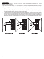
6. Fireplace Opening Dimensions.
A. Minimum Width 29˝ [737mm]
B. Minimum Height 23˝ [584mm]
C. Minimum Depth 14˝ [356mm]
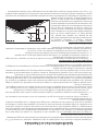
7. Combustible Material Clearances. The replace and
chimney must be inspected to make sure there is
adequate clearance to combustible materials. This
includes the top, side, front, and back as well as
concealed combustibles in the chimney and mantle
areas. Your local building inspector or re authority
should have information on whether older replace
meet current codes and are suitable for use. See also
gure 1 and gure 2.
D. Min. Distance to Sidewall 9˝ [228mm]
E. Min. Distance to Top Trim 14˝ [355mm]
F. Min. Distance to Mantle 19˝ [482mm]
G. Min. Distance to Side Trim 9˝ [228mm]
H. Min. Floor Protector Front 12˝ [304mm]
I. Min. Floor Protector Side 6˝ [152mm]
Min. Floor Protector Side Canada ....8” [203]
8. Makeup Air Requirements. This appliance requires
an adequate supply of makeup air to operate safely
and efciently. In some areas, this is a building code
requirement. Inadequate air supply will cause poor
combustion, inefcient operation, creosote buildup,
back drafting and smoke pufng into the living areas. If
any of the following conditions are evident, a makeup
air supply MUST be installed.

5
a. Existing fuel-red equipment shows evidence of back pufng, smoke roll-out, inefcient operation, or
excessive smell in the living area.
b. Opening a window or door alleviates any of the above problems or symptoms.
c. The building is constructed with a well-sealed vapor barrier, tight tting windows, or has powered exhaust
fans.
d. Excessive condensation on windows in the winter.
e. The building has a ventilation system installed.
f. If, once installed, the solid-fuel appliance does not draw steadily, burns poorly or inefciently, back-drafts or
experiences back-pufng when adding fuel.
VENTING (DRAFT) REQUIREMENTS
The chimney ue is a critical component to the proper and efcient operation of any heating appliance. Heating
appliances do not create draft, draft is provided by the chimney. This appliance requires a draft of 0.05 in. water
column (0.1 Pa) at the ue collar.
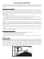
To achieve proper draft, your chimney must meet three minimum height requirements; minimum height from
top of appliance (15 ft. total height from top of appliance), minimum height above roof penetration (3 ft.), and
minimum height (2 ft.) above highest point of roof within a 10 ft. diameter from the chimney. The chimney must
also meet minimum and maximum cross sectional requirements. For that reason a continuous 6˝ stainless steel liner
from the ue collar to the top of the chimney is required. A stainless steel adapter is recommended for fastening
the stainless steel liner to the ue collar. The male (or crimped) end of the adapter must be installed inside the ue
collar to allow condensation or creosote in the liner to drain back into the rebox. Chimney liners and/or adapters
must be permanently fastened using a minimum of three (3) screws at each connection. Chimneys outside of the
home or on an exterior wall are difcult to keep at operating temperatures and may result in increased creosote
buildup, less draft, back drafting problems and poor appliance performance and should be avoided.
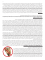
FLOOR PROTECTOR
A solid non-combustible oor, concrete or solid masonry, must extend 6˝ to either side of the body of the
appliance and 12˝ in front of the face of the appliance. When combustible ooring falls within these minimum
dimensions, it must be covered with a listed oor protector meeting the requirements of UL 1618, such as Hy-C
or Imperial Model UL 2840BK or equivalent with 0.84 R-factor, 1” thick. (Note: to calculate R-value of alternative
materials see Floor Protector Material Calculations at the back of this manual.) A grouted ceramic oor tile that
meets local building codes and the minimum 0.84 R-factor requirements is considered a durable equivalent.
US - 38 inches [965mm]
CAN - 42 inches [1.06M]
US - 6 in. [152mm]
CAN - 8 in. [203mm]
US - 6 in. [152mm]
CAN - 8 in. [203mm]
12 inches [305mm]
FLOOR PROTECTOR
Minimum Floor Protector Specificaons
WARNING: RIsk of re - do not allow combustible materials (carpet, furniture, fuels) to be placed on or cover
the oor protector. All combustible materials must remain outside of the minimum clearance dimensions.
WARNING: RISK OF FIRE - EXCESSIVE DRAFT CAN CAUSE OVERFIRING AND A POSSIBLE STRUCTURE FIRE. DO NOT
OPERATE THIS APPLIANCE WITH THE FLUE DRAFT EXCEEDING 0.06 in. w.c. (0.1 Pa).

6
Assembly Instructions
TOOLS AND MATERIALS REQUIRED FOR INSTALLATION
(NOTE: The following items are NOT included with your stove.)
• Pencil
• 6 foot Folding Ruler or Measuring Tape
• Tin Snips
• Drill: Hand or Electric
• 1/8” dia. Drill Bit (for sheet metal screws)
• Screwdrivers (Blade and Phillips type)
• 14mm Nut Driver or Ratchet with 14mm Socket
• Flooring Protection: as specied herein.
• Chimney Liner: Continuous stainless steel chimney
liner (as required)
• Stainless Steel Adapter (connects the liner to the
ue collar)
• 1/2” Sheet Metal Screws
• Furnace Cement (manufacturer recommends
Rutland Code 78 or equivalent)
• Fire Place Insert Surround Kit (TK004)
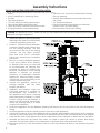
1. Clean the replace opening properly
disposing of any ashes in a closed metal
container. See Safety Instructions.
2. Install a 6˝ (152mm) minimum diameter,
continuous stainless steel chimney liner
into the existing chimney. The liner
must extend to the top of the existing
chimney. Use only listed chimney
liners that meet UL1777 standards.
Follow liner manufacturer installation
instructions.
3. Remove or lock the replace damper
in the open position. Note: Masonry
or damper plate may be removed
to accommodate the chimney liner
provided this does not weaken any
structural components of the existing
replace or chimney nor reduces
protection of combustible materials
required by national building codes.
Consult with your local building or re
authority before doing this.
4. Uncrate the appliance, remove all
packing materials, and any items
stored in the rebox.
5. WARNING: Any replace which has
had parts removed or modied to
accommodate the installation of
this appliance MUST have a warning
plate permanently installed in a visible
location stating that the replace is
unt for use with solid fuel. Permanently
attach the warning plate to a visible
location in the replace.
6. Position the appliance into the replace opening until the top lip of the air jacket is ush with the replace
facing.
7. Level the appliance with the adjusting screws at the rear of the appliance.
8. Connect the chimney liner to the appliance using a stainless steel adapter and securing with a minimum
of three (3) sheet metal screws. The liner MUST be attached with the male (or crimped) end of the adapter
inside the ue collar of the appliance to allow condensation and/or creosote to drain back into the rebox.
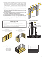
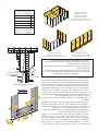
9. Assemble the Surround. Lay pieces face down on carpet or other soft surface to protect nish during
assembly. The Surround consists of two side panels, a top panel, and a decorative trim frame.
10. Bolt the top panel (1) to the side panels (2 and 14) so the top surfaces are ush to one another using items
3 and 4.
CAUTION: this appliance is heavy. Make sure that you have adequate help and use proper lifting techniques
whenever moving this appliance.

7
11. Assemble the trim frame. The trim consists of a left (6) and right
(5) side piece and a split top piece (left #8, right #7). These
are joined by corner connectors (11-13) and two straight center
connectors (9-10). These slide into the channel on the back of
the frame and are secured with two set screws (13) in each
piece.
12. The trim slides over the surround assembly and is secured at the
base of each side with a machine screw.
13. The Surround Assembly is then slid over the appliance. Slots in
the two side panels accommodate the hood at the top of the
appliance (gure 6).
14. The surround assembly is held in place with two springs at the
top of either corner of the appliance (gure 6).
15. Connect power cord of blower to grounded receptacle.
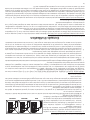
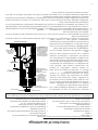
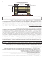
16. Firebrick extends the life of your stove and radiates heat more
evenly. If rebricks were removed to position appliance, replace
them before ring appliance. See gure 7 for proper orientation
and positioning. Install the back row rst, then sides and nally
install bottom rebricks.
1
14
2
6
5
7
8
3
4
9
10
11
12
13
SURROUND ASSEMBLY
VIEW FROM BACK
SPRING
SURROUND
Slots in surround
slide of rebox top
Figure 6. Surround Installation
A
A
A
A
A
B
B
B
B
B
B
A
A
A
A
D
C
C
E
A
A
A
A
A
B
B
B
B
B
B
A
A
A
A
D
C
C
E
A
A
A
A
A
B
B
B
B
B
B
A
A
A
A
D
C
C
E
Firebrick Dimensions: (inches)
A 4.50” x 9.00”
B 3.33” x 9.00”
C 3.38” x 9.00”
D 2.25” x 9.00”
E 1.25” x 2.25”
Note: All Firebrick is 1.25” Thick
Figure 7a -
Back Firebrick Arrangement
Five (5) A-Size
Figure 7b -
Side Firebrick Arrangement
Six (6) B-Size
Figure 7c -
Bottom Firebrick Arrangement
Four (4) A-Size
Two (2) C-Size
One (1) D-Size
One (1) E-Size
CAUTION: RISK OF FIRE!
• Replace rebricks before ring woodstove. Position rebricks
so no gaps remain between bricks.
• Never operate this appliance with missing or cracked
rebrick.
• Keep furnishings and other combustible materials away from
the stove and outside minimum clearances.

8
Chimney Specications
This appliance must be connected to a listed Stainless Steel Liner, that meets UL1777, which extends from the
collar to the chimney cap according to the specications listed on the previous pages. Take into account the
chimney’s location to insure it is not too close to neighbors or in a valley which may cause unhealthy or nuisance
conditions.
IMPORTANCE OF PROPER DRAFT
Draft is the force which moves air from the appliance up through the chimney. The amount of draft in your
chimney depends on the length of the chimney, local geography, nearby obstructions and other factors. Too
much draft may cause excessive temperatures in the appliance. Inadequate draft may cause backpufng into
the room and ‘plugging’ of the chimney. Inadequate draft will cause the appliance to leak smoke into the room
through appliance and chimney connector joints. An uncontrollable burn or excessive temperature indicates
excessive draft.
Chimneys perform two functions:
1. As a means of exhausting smoke and ue gases which are the result of fuel combustion.
2. The chimney provides “draft,” which allows oxygen to be continuously introduced into the appliance, so
that proper combustion is possible. This stove relies on natural draft to operate.
NOTICE: Always provide a source of fresh air into the room where the stove is located. Failure to do so may result
in air starvation of other fuel burning appliances and the possible development of hazardous conditions, re, or
death.
Your appliance itself does not create draft. Draft is provided by the chimney. To achieve proper draft your
chimney must meet the three minimum height requirements detailed in gure 8. A minimum draft of 0.05 w.c.
(measured in water column) is required for proper drafting to prevent back pufng, smoke spillage, and to
maximize performance. (Gauges to measure draft are readily available at stove stores and are economical to
rent or purchase.)
Factors such as wind, barometric pressure, trees, terrain and chimney temperature can have an adverse effect
on the draft. The manufacturer cannot be held responsible for external factors leading to less than optimal
drafting.
Should you have a problem with inadequate draft, you should contact a licensed heating and cooling contractor
for assistance in solving the problem.
IMPORTANT INSTALLATION POINTS
1. Size chimney ue to appliance collar. This stove requires a minimum 6” diameter ue.
2. Never connect this unit to a chimney serving another appliance.
3. The chimney must meet all minimum height requirements.
4. Never use a chimney to ventilate a cellar or basement.
Contact your local building authority for approved methods of installation and any necessary permits and/or
inspections.
MASONRY CHIMNEY
Before using an existing masonry chimney, clean the chimney, inspect the ue liner, and make any repairs
needed to be sure it is safe to use. As mentioned previously, this appliance requires a continuous stainless steel
liner from the appliance collar to the chimney cap. Make repairs before attaching the stove. The connector
stove pipe and ttings you will need to connect directly to a masonry chimney are detailed in the installation
instructions. If the replace chimney must go through a combustible wall before entering the main chimney,
consult a qualied mason or chimney dealer regarding proper materials that meet all local building and re
authority codes. The installation must conform to local building and re codes and latest edition of NFPA 211. If
there is a cleanout opening in the base of the chimney, close it tightly.

9
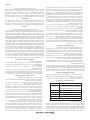
TYPE
WEIGHT
(LBS. CU. FT.,
DRY)
PER CORD
EFFICIENCY
RANKING
SPLITS
MILLIONS BTU’s/
CORD
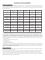
Hickory 63 4500 1.0 Well 31.5
White Oak 48 4100 .9 Fair 28.6
Red Oak 46 3900 .8 Fair 27.4
Beech 45 3800 .7 Hard 26.8
Sugar Maple 44 3700 .6 Fair 26.2
Black Oak 43 3700 .6 Fair 25.6
Ash 42 3600 .5 Well 25.0
Yellow Birch 40 3400 .4 Hard 23.8
Red Maple 38 3200 .3 Fair 22.6
Paper Birch 37 3100 .3 Easy 22.1
Elm/Sycamore 34 2900 .2 Very Difcult 20.1
Red Spruce 29 1800 .1 Easy 16.1
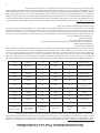
WOODSTOVE UTILIZATION
Your heating appliance was designed to burn wood only; no other materials should be burned. Waste and
other ammable materials should not be burned in your stove. Any type of wood may be used in your stove, but
specic varieties have better energy yields than others. Please consult the following table in order to make the
best possible choice.
Fuel Recommendations
It is EXTREMELY IMPORTANT that you use DRY WOOD only in your wood stove. The wood should have dried for
9 to 15 months, such that the humidity content (in weight) is reduced below 20% of the weight of the log. It is
very important to keep in mind that even if the wood has been cut for one, two, or even more years, it is not
necessarily dry, if it has been stored in poor conditions. Under extreme conditions it may rot instead of drying.
This point cannot be over stressed; the vast majority of the problems related to the operation of a wood stove is
caused by the fact that the wood used was too damp or had dried in poor conditions. These problems can be:
- ignition problems
- creosote build-up causing chimney res
- low energy yield
- blackened windows
- incomplete log combustion
Smaller pieces of wood will dry faster. All logs exceeding 6” in diameter should be split. The wood should not be
stored directly on the ground. Air should circulate through the cord. A 24” to 48” air space should be left between
each row of logs, which should be placed in the sunniest location possible. The upper layer of wood should be
protected from the element but not the sides.
TESTING YOUR WOOD
When the stove is thoroughly warmed, place one piece of split wood (about ve inches in diameter) parallel to
the door on the bed of red embers.
Keep the air control full open and close the door. If ignition of the piece is accomplished within 90 seconds from
the time it was placed in the stove, your wood is correctly dried. If ignition takes longer, your wood is damp.
If your wood hisses and water or vapor escapes at the ends of the piece, your wood is soaked or freshly cut
(green). Do not use this wood in your stove. Large amounts of creosote could be deposited in your chimney,
creating potential conditions for a chimney re.

10
Operating Instructions
CAUTIONS: HOUSE FIRE HAZARDS
• Do not store wood on oor protector, underneath stovepipe(s) if applicable, or anywhere within
clearances to combustible surfaces specied for this appliance.
• Never operate with secondary tubes, ber board, or insulation removed.
OPERATING SAFETY PRECAUTIONS
• Never overre this appliance by building excessively hot res as a house/building re may result. You are
overring the appliance if it begins to glow or turn red.
• Never build excessively large res in this type of appliance as damage to the rebox or smoke leakage
may result.
• Do not build re too close to glass.
• Hot while in operation. Keep children, clothing, and furniture away. Contact may cause skins burns. Do not
touch the appliance until it has cooled.
• Provide adequate air for combustion to the room where the appliance is installed.
• Inspect chimney liner every 60 days. Replace liner immediately if it is rusting or leaking smoke into the
room.
• Attempts to achieve heat output rates that exceed heater design specications can result in permanent
damage to the heater.
WARNING: EXPLOSION HAZARD
• Never use chemicals, gasoline, gasoline-type lantern fuel, kerosene, charcoal lighter uid, or similar
ammable liquids to start or “freshen up” a re in the appliance.
• Keep all ammable liquids, especially gasoline, out of the vicinity of the appliance - whether in use or in
storage.
THIS APPLIANCE IS DESIGNED TO BURN NATURAL WOOD FUEL ONLY!
Hardwood, 17” to 19”, should be split and air dried (seasoned) for 6 months to obtain maximum burning efciency.
Wood should be stored in a dry, well ventilated area.
Burning fuels other than intended, chemicals, or waste in this appliance could result in damages to the heater
or result in bodily injury. It will also void any warranty on the appliance.
This heater is designed to burn natural wood only. Higher efciencies and lower emissions generally result when
burning air dried seasoned hardwoods, as compared to softwoods or to green or freshly cut hardwoods.
DO NOT BURN:
1. Garbage;
2. Lawn clippings or yard waste;
3. Materials containing rubber, including tires;
4. Materials containing plastic;
5. Waste petroleum products, paints or paint thinners, or asphalt products;
6. Materials containing asbestos;
7. Construction or demolition debris;
8. Railroad ties or pressure-treated wood;
9. Manure or animal remains;
10. Salt water driftwood or other previously salt water saturated materials;
11. Unseasoned wood; or
12. Paper products, cardboard, plywood, or particleboard. The prohibition against burning these materials does
not prohibit the use of re starters made from paper, cardboard, saw dust, wax and similar substances for the
purpose of starting a re in an affected wood heater.
Burning these materials may result in release of toxic fumes or render the heater ineffective and cause smoke.
Dead wood lying on the forest oor should be considered wet, and requires full seasoning time. Standing dead
wood can usually be considered to be about 2/3 seasoned. Splitting and stacking wood before it is stored
accelerates drying time. Storing wood on an elevated surface from the ground and under a cover or covered
area from rain or snow also accelerates drying time. A good indicator if wood is ready to burn is to check the
piece ends. If there are cracks radiating in all directions from the center then the wood should be dry enough
to burn. If your wood sizzles in the re, even though the surface is dry, it may not be fully cured, and should be
seasoned longer.

11
Do not burn manufactured logs made of wax impregnated sawdust or logs with any
chemical additives. Manufactured logs made of 100% compressed sawdust can be
burned, but be careful burning too much of these logs at the same time. Start with one
manufactured log and see how the stove reacts. You can increase the number of logs
burned at a time to making sure the temperature never rises higher than 475 °F (246 °C)
on a magnetic thermometer for installation on single wall stove pipes or 900 °F (482 °C)
on a probe thermometer for installation on double wall stove pipe. The thermometer
should be placed about 18” (457 mm) above the stove. Higher temperatures can lead
to overheat and damage your stove.
OPTIMAL FUEL CONSUMPTION
This appliance is designed to get the most efcient transfer of heat energy from the wood fuel and radiate it into
your living environment. The re box introduces combustion air through three sources; (1) Immediately beneath
the door opening below the window is a Lower Primary Air Orice (LPAO), (2) The door air inlet control brings air
into the rebox and controls the rate of burn (and the amount of heat the appliance radiates), (3) The secondary
air tubes at the top of the rebox are designed to ignite the combustion gases (smoke) given off by the burning
wood and increases the efciency of the appliance and reduces chimney emissions.
Smoke given off by burning fuel consists of very small organic liquid droplets. If these droplets condense, they
form a sticky tar-like substance called creosote. When operated properly, this appliance is designed to burn these
droplets. Burning these droplets releases heat that would otherwise be lost up the chimney as smoke. Following
the instructions below will help you operate your appliance properly to maximize the appliance’s performance.
Actual performance is dependent on chimney height, weather, log size, wood species, and moisture content.
Some experimentation will initially be required to nd that spot where your appliance performs best. The following
will give you a starting point to nd your optimum settings.
When rst loading fuel, set the door air inlet control at the wide open position for at least 15–20 minutes. When
the appliance is working properly, you should be able to observe secondary combustion ames above the fuel
pieces in front of the secondary air tubes at the top of the rebox. These secondary ames should continue
to burn after the primary air inlet is reset from wide open to the desired operating setting. If the ames do not
continue to burn, open the air control to re-establish the secondary ames then slowly reset the air control to the
desired setting. Initially it may take several attempts to gure your appliance out. But once you nd the efcient
operating spot and the correct mix of procedures to get there, only minor adjustments will be necessary.
The best indicator of a properly operating appliance is to look for smoke coming out of the chimney. You may
see steam emissions that will quickly dissipate. Smoke will thin but continue to drift without totally disappearing.
If you do detect smoke emissions, open the air control a little bit, let the appliance adjust for 10–15 minutes and
re-check your chimney. Remember – visible smoke represents lost heat.
TAMPER WARNING
This wood heater has a manufacturer-set minimum low burn rate that must not be altered. It is against federal
regulations to alter this setting or otherwise operate this wood heater in a manner inconsistent with operating
instructions in this manual.
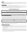
EFFICIENCIES
Efciencies can be based on either the lower heating value (LHV) or the higher heating value (HHV) of the fuel.
The lower heating value is when water leaves the combustion process as a vapor, in the case of woodstoves the
moisture in the wood being burned leaves the stove as a vapor. The higher heating value is when water leaves
the combustion process completely condensed. In the case of woodstoves this would assume the exhaust gases
are room temperature when leaving the system, and therefore calculations using this heating value consider
the heat going up the chimney as lost energy. Therefore, efciency calculated using the lower heating value of
wood will be higher than efciency calculated using the higher heating value. In the United States all woodstove
efciencies should be calculated using the higher heating value.
The best way to achieve optimum efciencies is to learn the burn characteristic of you appliance and burn well-
seasoned wood. Higher burn rates are not always the best heating burn rates; after a good re is established a
lower burn rate may be a better option for efcient heating. A lower burn rate slows the ow of usable heat out
of the home through the chimney, and it also consumes less wood.
Notice: Use solid wood fuel only! Do not burn garbage , or ammable uids. Do not use coal. This appliance
is not designed to accommodate the air ow (draft) required to properly burn coal or coal products. Do not
elevate the re using grates or irons. Build the re directly on the rebrick.

12
NOTICE - INITIAL BURNS TO CURE PAINT
BECAUSE OF THE HIGH OPERATING TEMPERATURES, THIS APPLIANCE IS COATED WITH A SPECIAL HIGH TEMP PAINT
WHICH REQUIRES A SERIES OF LOW TO MEDIUM BURNS TO FULLY CURE FOR DURABILITY AND A LIFETIME OF SERVICE.
Proper curing of the high-temp paint requires a series of three initial burns. The appliance should be allowed to
cool off between each burn. The rst two burns should be small res and low temperatures (250 degrees F) for
a duration of 20 minutes each. The third re should be at a temperature of approximately 500 F for 20 minutes.
Provide adequate cross ventilation to clear any smoke or odor caused by initial rings.
STARTING A FIRE
DO NOT LEAVE APPLIANCE UNATTENDED WITH DOOR OPEN! The top down method of re building is recommended
for this appliance. After making sure that the stove air intake controls are fully open (completely pull-out towards
you), Place the largest pieces of wood on the bottom, laid in parallel and close together. Smaller pieces are
placed in a second layer, crossways to the rst. A third layer of still smaller pieces is laid crossways to the second,
this time with some spaces between. Then a fourth layer of loose, small kindling and twisted newspaper sheets
tops off the pile. Add large pieces of wood as the re progresses being careful not to overload. (Do not ll rebox
beyond rebrick area.) An ideal ember bed of 1 – 2” should be established to achieve optimum performance.
This unit is designed to function most effectively when air is allowed to circulate to all areas of the rebox. TIP: If
ash or embers remain in the appliance, make sure to clear them away from the Lower Primary Air Orice (LPAO)
and rake a slight (1-to-2 inch wide) trough down the center of the embers from front to back prior to loading
the fuel. Once fuel has been loaded, close the door and leave the air inlet control fully open until re is well
established (at least 15–20 minutes) being careful not to over re (if any of the exterior parts of the appliance
or chimney connections begin to glow you are over ring the appliance). Re-adjust the door air inlet control to
desired burn rate. (If excessive smoke lls the rebox, open air inlet control slightly until ames resume and wood
is sufciently ignited.) The basic rule of thumb is “closed - low,” “half way open - medium” and “fully open - high.”
The amount of visible smoke being produced can be an effective method of determining how efciently the
combustion process is taking place at the given settings. Visible smoke consist of unburned fuel and moisture
leaving your stove. Learn to adjust the air settings of your specic unit to produce the smallest amount of visible
smoke. Wood that has not been seasoned properly and has a high wood moisture content will produce excess
visible smoke and burn poorly.
ADDING FUEL
If the embers are not hot and glowing, rake the embers to the front of the appliance, close the door and adjust
the air inlet control to the wide open position. Let the embers re-heat for 10–15 minutes. When hot and glowing,
spread them out and place your next fuel load into the appliance (make sure no embers or ashes block the
LPAO). Leave the door air inlet control in the wide open position for 15–20 minutes.
Fuel load size can vary but should be kept 1–2 inches below the secondary air tubes. Also position the fuel to
leave space so the air from the inlet can work down between the pieces of fuel. This reduces the time it takes for
new fuel to burn properly.
1. When refueling, adjust air inlet control to the fully open position. When re brightens, slowly and carefully
open the door. This procedure will prevent gases from igniting causing smoke and ame spillage.
2. Add fuel being careful not to overload or overre the appliance.
3. When adding fuel be careful not to smother the re. Do not build res against glass and make sure the
embers do not obstruct the air inlet. Do not allow logs to roll and strike the glass.
4. Close the feed door and secure tightly.
5. Adjust the air inlet control as described above.
6. Empty ashes regularly. Do not allow ashes to pile up.
7. Properly dispose of hot ashes.
8. Do not overre the appliance (overring is when any part of the appliance’s exterior or chimney connections
glow).
OPERATIONAL TIPS
• Get the appliance hot and establish a good coal bed before adjusting to a low burn rate (this may take 30
minutes or more depending on your wood)
• Use smaller pieces of wood during start-up and a high burn rate to increase the stove temperature
• Be considerate of the environment and only burn dry wood
• Burn small, intense res instead of large, slow burning res when possible
• Learn your appliance’s operating characteristics to obtain optimum performance
• Burning unseasoned wet wood only hurts your stoves efciency and leads to accelerated creosote buildup
in your chimney

13
AIR TUBES
The air tubes assembled in this unit are designed to provide an accurate mix of secondary air to insure the
highest efciency. Any damage or deterioration of these tubes may reduce the efciency of combustion. The
air tubes are held in position by either screws or snap pins. Locate these to either side of the tube and remove to
allow the tube to be removed and replaced.
BLOWER OPERATION
The variable speed blower circulates air warmed by the rebox into the living area to distribute the heat more
evenly. The blower control knob is located on the side of the blower housing.
Turn the knob clockwise to turn the blower on. The speed is controlled by turning the knob clockwise for slower
speeds and counter-clockwise for faster speeds. To turn the blower off, turn the speed control knob fully counter-
clockwise. It is recommended to turn the blower off when the unit is not in operation.
CAUTION:
Do not overre appliance. You are overring if any part of the appliance glows red. Close the door and shut
damper immediately to reduce the air supply and slow down the re.
Chimney Maintenance
CAUTION:
Slow burning res for extended use or burning green wood may cause excessive creosote build-up. Ignition
of creosote or overring could cause a chimney re. Chimney res burn extremely hot and may ignite
surrounding combustible materials. In case of a chimney re, call the re department immediately!
CREOSOTE - FORMATION AND REMOVAL
When wood is burned slowly, it produces tar and other organic vapors which combine with expelled moisture
to form creosote. The creosote vapors condense in the relatively cool chimney ue of a slow-burning re and
can accumulate on the ue lining. If ignited, this creates an extremely hot re in the chimney which may ignite
surrounding materials resulting in a building re. The chimney connector and chimney should be inspected (at
least) twice a month during the heating season to determine if a creosote buildup has occurred. If it has, it should
be removed. Failure to remove creosote may result in ignition and may cause a house/building re. Creosote
may be removed using a chimney brush or other commonly available materials from your local hardware retailer.
Chimney res burn very hot. If the unit or chimney connector should glow red, reduce the re by closing the inlet
air control and immediately call the re department. A re in the rebox may be smothered by pouring a large
quantity of coarse salt, baking soda, or cool ashes on top of the re.
PREVENTING CREOSOTE BUILD-UP
1. Burn with air control open for several minutes at numerous intervals throughout the day during the heating
season, being careful not to overre the unit.
2. Burn appliance with air inlet control wide open for 15–20 minutes every time you apply fresh wood. This allows
wood to achieve the charcoal stage faster and burns wood vapors which might otherwise be deposited
within the heating system.
3. BURN ONLY SEASONED WOOD. Avoid burning wet or green wood. Seasoned wood has been dried for at
least one year.
4. A small hot re is preferable to a large smoldering one that can deposit creosote within the heating system.
5. Establish a routine for the handling of fuel, wood burner and ring technique. Check daily for creosote
buildup until experience shows how often you need to clean for safe operation. Be aware that the hotter
the re, the less creosote is deposited, and weekly cleaning may be necessary in mild weather even though
monthly cleaning may be enough in colder months.
CAUTION:
A chimney re may cause ignition of wall studs or rafters which were assumed to be a safe distance away from
the chimney. If a chimney re occurs, have your chimney inspected by a qualied expert before using again.

14
CHIMNEY DRAFT
NOTE: A DRAFT READING OF 0.05[12.45] to 0.06[14.94] (Water Column[Pascals]) IS REQUIRED FOR PROPER
BURNING OF THIS APPLIANCE.
Draft is a function of the chimney, NOT THE APPLIANCE — Do not expect the appliance to draw. Smoke spillage
into the house or excess buildup of condensation or creosote in the chimney are warnings that the chimney is
NOT functioning properly. Correct the problem before using the appliance. Following are some possible causes
for improper draft.
1. The connector pipe may be pushed into the chimney too far, stopping the draft.
2. If the chimney is operating too cool, water will condense in the chimney and run back into the appliance.
Creosote formation will be rapid and may block the chimney. Operate the appliance at a re level high
enough to keep the chimney warm preventing this condensation.
3. If the re burns well but sometimes creates excessive smoke or burns slowly, it may be caused by the chimney
top being lower than another part of the house or a nearby tree. The wind blowing over a house or tree falls on
top of the chimney like water over a dam, beating down the smoke. The top of the chimney should be at least
three (3) feet above the roof and be at least two (2) feet higher than any point of the roof within ten (10) feet.

15
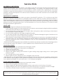
ASH REMOVAL AND DISPOSAL
Whenever ashes get 3 to 4 inches deep in your rebox or ash pan, and when the re has burned down and
cooled, remove excess ashes. Leave an ash bed approximately 1 inch deep on the rebox bottom to help
maintain a hot charcoal bed. Ashes should be placed in a metal container with a tight-tting lid. The closed
container of ashes should be placed on a noncombustible oor or on the ground, away from all combustible
materials, pending nal disposal. The ashes should be retained in the closed container until all cinders have
thoroughly cooled.
SMOKE AND CO MONITORS
Burning wood naturally produces smoke and carbon monoxide(CO) emissions. CO is a poisonous gas when
exposed to elevated concentrations for extended periods of time. While the modern combustion systems in
heaters drastically reduce the amount of CO emitted out the chimney, exposure to the gases in closed or conned
areas can be dangerous. Make sure your stove gaskets and chimney joints are in good working order and sealing
properly to ensure unintended exposure. It is recommended that you use both smoke and CO monitors in areas
having the potential to generate CO.
GLASS CARE
The following usage and safety tips should be observed:
1. Inspect the glass regularly for cracks and breaks. If you detect a crack or break, extinguish the re immediately
and contact the manufacturer for a replacement.
2. Do not slam the door or otherwise impact the glass. When closing doors, make sure that logs or other objects
do not protrude to impact the glass.
3. Do not build res against (or that might fall against) the glass.
4. Do not clean the glass with materials that may scratch (or otherwise damage) the glass. Scratches on the
glass can develop into cracks or breaks during operation.
5. Never attempt to clean the glass while the unit is hot. If deposits are not very heavy, normal glass cleaners are
adequate using a soft, non-abrasive cleaning pad. Heavier deposits may be removed with oven cleaners.
6. Never put substances which can ignite explosively in the unit. Even small explosions in conned areas can
blow out the glass.
Gasket and Glass cleaning products are available at local retail home centers. Manufacturers of cleaning products
for wood stoves include, A.W. Perkins Co. (www.awperkins.com) or Rutland Products (www.rutland.com).
GLASS REPLACEMENT
1. Ensure appliance is not in operation and is thoroughly cooled.
2. Remove screw and glass clip. (See parts list and diagram.)
3. Lift glass out from glass clip.
4. Remove old gasket and clean glass.
5. Replace new gasket starting at the bottom of glass working along edges, being sure to center gasket
channel on glass.
6. Trim to length and butt ends together.
7. Replace glass into door, being sure not to overtighten screw and clip.
After extensive use, the gasket material which provides glass and door seal may lose it’s resiliency and will need
to be replaced. Inspect glass and door gaskets periodically to ensure proper seal; if gaskets become frayed or
worn, replace immediately. This unit’s door uses a 1-1/8” diameter rope gasket.
DOOR GASKET REPLACEMENT
1. Ensure appliance is not in operation and is thoroughly cooled.
2. Remove old door gasket and clean channel.
3. Using an approved, high temperature gasket cement, apply a thin coat in bottom of channel.
4. Starting at hinge side of door, work gasket into channel around door unit, end butt and trim to length.
5. Close door and allow three to four hours for cement to set before ring appliance.
Service Hints
CAUTION:
Replace glass only with 5mm high temperature ceramic glass of the proper size. Do not use tempered glass
or double thickness window glass.

16
ATTENTION:
This wood heater needs periodic inspection and repair for proper operation. It is against federal regulations
to operate this wood heater in a manner inconsistent with operating instructions in this manual.
The stove must be placed on solid concrete, solid masonry, or when installed on a combustible oor, on a Type 2 oor protector listed to
standard UL 1618 with a minimum R value of 1.2 or equivalent. The oor protector is required to provide heat, live ember, and ash protection
and must be of a non-combustible, continuous solid surface to protect against inltration of live embers and ash. For UL Listed oor protectors,
refer to manufacturers instructions for installation directions. Manufacturers of listed oor protectors include Imperial Metal Products and Hy-C
among others. To calculate R-Values for alternative methods, see below for calculation methods.
Alternate materials may be rated with C-factor (Thermal Conductance) or k-factor (Thermal Conductivity) ratings which must be converted
to R-value to determine if the alternate material meets the tested requirements. The following instructions provide the proper information and
formulas for conversion to R-value.
To determine if alternate materials are acceptable follow this sequence.
1. Convert material specications to R-value:
a. R-value given — no conversion necessary
b. k-factor is given with a required thickness (T) in inches: R = 1/k x T
c. C-factor is given: R = 1/C
2. Determine the R-value of proposed alternate oor protector:
a. Use formulas in step 1 above to calculate R-value of proposed material(s).
b. For multiple layers, add R-values of each layer to determine overall R-value.
3. If the overall R-value of the oor protector system is equal to or greater than the oor protector specications given, the alternate is
acceptable.
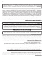
Denitions:
Thermal conductance (C) = =
Thermal conductivity (k) = = =
Thermal resistance (R) = =
Example:
The specs of oor protector material should be 3/4-inch thick material with a k-factor of 0.84. The proposed alternative material is 4” brick with
a C-factor of 1.25 over 1/8-inch mineral board with a k-factor of 0.29.
Step 1: Convert specs to R-value.
R = 1/k x T = 1/0.84 x 0.75 = 0.893 System must have a R-value of 0.893 = Rspecs
Step 2: Calculate R-value of individual components
4” Brick with C-factor = 1.25. R = 1/C = 1/1.25 = 0.80 = Rbrick
1/8-inch (0.125”) mineral board with k-factor = 0.29. R = 1/0.29 x 0.125 = 0.431 = Rmin.brd.
Step 3: Add R-values of components to get total R-value of system
Rbrick + Rmin.brd = 0.80 + 0.431 = 1.231 = Rsystem
Step 4: Compare Rsystem to Rspecs
Rsystem = 1.231 is larger than Rspecs of 0.893. System R-value exceeds the required specications and therefore is an acceptable alternative.
BTU
(hr)(ft²)(°F)
W
(m²)(°K)
(Btu)(inch)
(hr)(ft²)(°F)
W
(m²)(°K)
BTU
(hr)(ft²)(°F)
(hr)(ft²)(°F)
BTU
(m²)(°K)
W
REMOVING THE INSERT FOR PURPOSE OF INSPECTION
If for any reason you must remove the insert for inspection of the appliance or replace, follow these rules.
1. Ensure appliance is not in operation and is thoroughly cooled.
2. Remove the surround by removing the springs retaining it to the appliance.
3. Disconnect the ue gas pipe from the appliance.
4. Slide appliance out to perform inspection.
Floor Protector

17
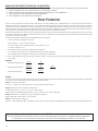
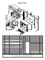
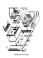
Repair Parts
19
17
18
15
14
14
1
20
9
8
24
25
31
32
28
30
29
27
21
22
26
13
12
11
10
16
23
2
3 4
5
6
7
Key Part No. Description Qty.
1 69660 Complete Door Assembly 1
2 88066 5/8” Rope Gasket 6 ft.
3 891813 Door Glass 1
4 88174
Gasket-Flat, Glass (3/16T x
3/8W)
6 ft.
5 25465 Glass Retainers 2
6 83202
Machine Screw - 10-24 x 3/8
Ph Hd.
4
7 83278 Washer - 7/32 ID X 1/2 OD 4
8 891373 Hinge Pad 2
9 25080
Door Latch (Uses 83508 - 5/16-
18 x 3/4 bolt)
1
10 89066 Firebrick (4.5 x 9) 9
11 891989-1 Firebrick (3.33 x 9) 6
12 891414 Firebrick (2.25 x 9) 1
13 891989-2 Firebrick (1.25 x 2.25) 1
14 86669 Tube #1, Secondary Comb. 2
15 86670 Tube #2, Secondary Comb. 1
Key Part No. Description Qty.
16 891990 Retainer, Tube 3
17 88158 Fiber Board, Front 1
18 88159 Fiber Board, Rear 1
19 88160 Fiber Blanket 1
20 80598 Blower Assembly 1
21
TK004
(optional)
Surround, Top 1
22 Surround, Left Side 1
23 Surround, Right Side 1
24 Spring 2
25 Trim-R, Surround 1
26 Trim-L, Surround 1
27 Trim-Top_L, Surround 1
28 Trim-Top_R, Surround 1
29 Key, Straight 1
30 Key, Blank Straight 1
31
Key, Blank Corner (Can Use
89420)
2
32 Key, Corner (Can Use 89419) 2
In order to maintain warranty, components must be replaced using original manufacturers parts purchased
through your dealer or directly from the appliance manufacturer.
Use of third party components will void the warranty.

The operation of this unit in a manner inconsistent with the owner’s manual
will void the warranty and is also against federal regulations. United States
Stove Company warrants this product to be free from defects in material and
workmanship, to the original retail purchaser only, for the time period identified
below, measured from the date of the initial purchase as evidenced on an
invoice, cancelled check, sales receipt, etc., to receipt of a claim by United
States Stove Company (“USSC”) or an authorized dealer, as follows:
WARRANTY CONDITIONS
• This warranty only covers USSC appliances that are purchased through an
USSC authorized retailer, dealer or distributor.
• This warranty is only valid while the USSC appliance remains at the site of
original installation. This warranty does not apply to products purchased for
rental use.
CLAIM PROCEDURE
Contact United States Stove Company for warranty service. You will be asked
to provide detailed descriptions and pertinent data, including proof or purchase
which will be returned upon request. Providing the heater has been installed
and used in accordance with the Owner’s Manual supplied with the heater
and the issue does not fall under a situation of exclusion, United States Stove
Company will either:
• Replace the defective part free of charge. Parts and/or service replacements
made under the terms of this warranty are warranted only for the remaining
period of the original heater warranty.
• Replace the heater free of charge. Should the heater be replaced by United
States Stove Company “free of charge”, all further warranty obligations are
thereby met.
• Where the defect is of a cosmetic (non-functional) nature, United States
Stove Company will bear reasonable expense to repair the heater, including
such items as welding, painting, and incidental labor. A “reasonable expense”
is defined by terms of this warranty as $30.00/hour with full refund for any
purchase of parts.
WARRANTY EXCLUSIONS
This warranty does not cover the following:
• Damage to or changes in surface finishes as a result of normal use. As a heating
appliance, some changes in color or interior and exterior surface finishes may
occur. This is not a flaw and is not covered under warranty.
• Damage to printed, plated, or enameled surfaces caused by fingerprints,
accidents, misuse, scratches, melted items, or other external sources and
residues left on the plated surfaces from the use of abrasive cleaners or polishes.
• Repair or replacement of parts that are subject to normal wear and tear during
the warranty period. These parts include: paint, pellet, and the discoloration
of glass.
• Minor expansion, contraction, or movement of certain parts causing noise.
These conditions are normal and complaints related to this noise are not
covered by this warranty.
• Damages resulting from: (1) failure to install, operate, or maintain the appliance
in accordance with the installation instructions, operating instructions, and
listing agent identification label furnished with the appliance; (2) failure to
install the appliance in accordance with local building codes and/or authorities
having jurisdiction; (3) shipping or improper handling; (4) improper operation,
abuse, misuse, continued operation with damaged, corroded or failed
components, accident, alteration, or improperly/incorrectly performed repairs;
(5) environmental conditions, weather, inadequate ventilation, negative
pressure, or drafting caused by tightly sealed constructions, insufficient make-
up air supply, or handling devices such as exhaust fans or forced air furnaces
or other such causes; (6) use of fuels other than those specified in the operating
instructions; (7) installation or use of components not supplied with appliance
or any other components not expressly authorized and approved by USSC; (8)
modification of the appliance not expressly authorized and approved by USSC
in writing; and/or (9) interruptions or fluctuations of electrical power supply
to the appliance.
• Non-USSC venting components, hearth components or other accessories used
in conjunction with the appliance.
• USSC’s obligation under this warranty does not extend to the appliance’s
capability to heat the desired space. Information is provided to assist the
consumer and the dealer in selecting the proper appliance for the application.
Consideration must be given to appliance location and configuration,
environmental conditions, insulation and air tightness of the structure.
• Problems relating to smoking or creosote. Smoking is attributable to inadequate
draft due to the design or installation of the flue system or installation of the
heater itself. Creosote formation is largely attributable to improper operation of
the unit and/or draft as mentioned above.
• Any cost associated with product removal and re-installation, travel,
transportation, or shipping.
• Service calls to diagnose trouble (unless authorized in writing by the
manufacturer, distributor, or dealer).
THIS WARRANTY IS VOID IF
• The appliance has been over-fired or operated in atmospheres contaminated by
chlorine, fluorine, or other damaging chemicals. Over-firing can be identified
by, but not limited to, warped plates or tubes, rust colored cast iron, bubbling,
cracking and discoloration of steel or enamel finishes.
• The appliance is subjected to prolonged periods of dampness or condensation.
• There is any damage to the appliance or other components due to water or
weather damage which is the result of, but not limited to, improper chimney or
venting installation.
LIMITATIONS OF LIABILITY
The owner’s exclusive remedy and USSC’s sole obligation under this warranty,
under any other warranty, express or implied, or in contract, tort or otherwise,
shall be limited to replacement, repair, or refund, in USSC’s sole and absolute
discretion. In no event will USSC be liable for any incidental or consequential
damages. THE LIMITED WARRANTY SET FORTH HEREIN IS THE
SOLE WARRANTY PROVIDED TO PURCHASER AND IS IN LIEU OF
ALL OTHER WARRANTIES AND REPRESENTATIONS, EXPRESS OR
IMPLIED. USSC MAKES NO REPRESENTATIONS OR WARRANTIES
WHATSOEVER, EXPRESS OR IMPLIED, WITH RESPECT TO THE
PRODUCT, OTHER THAN (i) THE LIMITED WARRANTY ABOVE, AND
(ii) ANY IMPLIED WARRANTIES IMPOSED BY APPLICABLE LAW
WHICH CANNOT BE WAIVED OR DISCLAIMED UNDER APPLICABLE
LAW. ALL OTHER WARRANTIES OF ANY KIND, INCLUDING WITHOUT
LIMITATION IMPLIED WARRANTIES OF MERCHANTABILITY AND
FITNESS FOR A PARTICULAR PURPOSE, ARE HEREBY DISCLAIMED
AND EXCLUDED TO THE FULLEST EXTENT NOT PROHIBITED BY
APPLICABLE LAW. This Limited Warranty gives the purchaser specific
legal rights; a purchaser may have other rights depending upon where he or
she resides. Some states do not allow the exclusion or limitation of special,
incidental or consequential damages, or state law may affect the duration of
limitations, so the above exclusion and limitations may not be applicable.
WARRANTOR
The warrantor of record is United States Stove Company, PO Box 151, 227
Industrial Park Road, South Pittsburg, Tennessee 37380. Phone number: (800)-
750-2723. Register your product on line at www.usstove.com. Save your proof
of purchase, as documented in a receipt or invoice, with your records for any
claims.
IMPORTANT
We congratulate you on your selection of United States Stove Company and
its products. As the oldest solid fuel manufacturer in the United States (since
1869), the United States Stove Company is very proud of its products, service,
employees, and satisfied customers. We would like to hear from you if you are
not satisfied with the manner in which you have been handled by our distributor,
dealer, representative, customer service department, parts department, or sales
department. Please reach out to us by using any of the contact information
listed above.
Limited Warranty
852942B
TIME PERIOD
Firebox / Heat Exchanger Limited Lifetime
Door One Year
Cabinets and Trim One Year
Gaskets One Year
All Electrical Components (Blower, Auger
/ Agitator Motor, PC Board, Switches)
One Year
Ceramic Glass One Year

Service 01 Date:________________________
Engineer Name:_____________________________________
Company:__________________________________________
Telephone No.:______________________________________
Stove Inspected: Chimney Swept:
Items Replaced:____________________________________
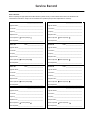
It is recommended that your heating system is serviced regularly and that the appropriate Service Interval Record is completed.
Service Provider:
Before completing the appropriate Service Record below, please ensure you have carried out the service as described in the
manufacturer’s instructions. Always use the manufacturer's specified spare part when replacement is necessary.
Service Record
Service 02 Date:________________________
Engineer Name:_____________________________________
License No.:________________________________________ License No.:_______________________________________
Company:_________________________________________
Telephone No.:______________________________________
Stove Inspected: Chimney Swept:
Items Replaced:____________________________________
Service 03 Date:________________________
Engineer Name:_____________________________________
Company:__________________________________________
Telephone No.:______________________________________
Stove Inspected: Chimney Swept:
Items Replaced:____________________________________
Service 04 Date:________________________
Engineer Name:_____________________________________
Company:________________________________________
Telephone No.:______________________________________
Stove Inspected: Chimney Swept:
Items Replaced:____________________________________
Service 05 Date:________________________
Engineer Name:_____________________________________
Company:__________________________________________
Telephone No.:______________________________________
Stove Inspected: Chimney Swept:
Items Replaced:____________________________________
Service 06 Date:_______________________
Engineer Name:_____________________________________
Company:_________________________________________
Telephone No.:______________________________________
Stove Inspected: Chimney Swept:
Items Replaced:____________________________________
Service 07 Date:________________________
Engineer Name:_____________________________________
Company:__________________________________________
Telephone No.:______________________________________
Stove Inspected: Chimney Swept:
Items Replaced:____________________________________
Service 08 Date:_______________________
Engineer Name:_____________________________________
Company:_________________________________________
Telephone No.:______________________________________
Stove Inspected: Chimney Swept:
Items Replaced:____________________________________
License No.:_______________________________________ License No.:_______________________________________
License No.:_______________________________________ License No.:_______________________________________
License No.:_______________________________________ License No.:_______________________________________
Service Record

This manual will help you obtain efcient, dependable service from your heater, and
enable you to order repair parts correctly.
Keep this manual in a safe place for future reference.
When writing, always give the full model number which is on the nameplate attached to
the heater.
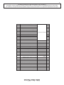
When ordering repair parts, always give the following information as shown in this list /
Ce manuel vous permettra d’obtenir une utilisation efcace et able de votre appareil
de chauffage et de commander
correctement les pièces de rechange.
Gardez ce manuel dans un lieu sûr pour reference ulterieure.
Lors d’une correspondance, donnez toujours le numéro de modèle complet qui est inscrit
sur la plaque attachée à l’appareil de chauffage.
Lors de la commande de pièces de rechange, donnez toujours les informations dans
l’ordre suivant:
1. The Part Number / Le Numéro De Pièce ____________________________________________
2. The Part Description / La Description De La Pièce ___________________________________
3. The Model Number / Le Numéro De Modéle _______________________________________
4. The Serial Number / Le Numéro De Série ___________________________________________
How To Order Repair Parts /
Comment Commander Les Pièces De Rechange
U.S. STOVE
227 industrial park road
South Pittsburg, tn 37380, USA
(800)750-2723
www.usstove.com
La page est en cours de chargement...
La page est en cours de chargement...
La page est en cours de chargement...
La page est en cours de chargement...
La page est en cours de chargement...
La page est en cours de chargement...
La page est en cours de chargement...
La page est en cours de chargement...
La page est en cours de chargement...
La page est en cours de chargement...
La page est en cours de chargement...
La page est en cours de chargement...
La page est en cours de chargement...
La page est en cours de chargement...
La page est en cours de chargement...
La page est en cours de chargement...
La page est en cours de chargement...
La page est en cours de chargement...
La page est en cours de chargement...
La page est en cours de chargement...
-
 1
1
-
 2
2
-
 3
3
-
 4
4
-
 5
5
-
 6
6
-
 7
7
-
 8
8
-
 9
9
-
 10
10
-
 11
11
-
 12
12
-
 13
13
-
 14
14
-
 15
15
-
 16
16
-
 17
17
-
 18
18
-
 19
19
-
 20
20
-
 21
21
-
 22
22
-
 23
23
-
 24
24
-
 25
25
-
 26
26
-
 27
27
-
 28
28
-
 29
29
-
 30
30
-
 31
31
-
 32
32
-
 33
33
-
 34
34
-
 35
35
-
 36
36
-
 37
37
-
 38
38
-
 39
39
-
 40
40


United States Stove Colonial TR004 Le manuel du propriétaire
- Catégorie
- Cheminées
- Taper
- Le manuel du propriétaire
- Ce manuel convient également à
dans d''autres langues
Documents connexes
Autres documents
-
United States Stove Company VG1820 Le manuel du propriétaire
-
US Stove Company US1800E Le manuel du propriétaire
-
Ashley Hearth Products AW1820E Le manuel du propriétaire
-
 Regency Fireplace Products Classic F2450 Le manuel du propriétaire
-
 Regency Fireplace Products Pro-Series F3500 Le manuel du propriétaire
-
USSC TR001B Le manuel du propriétaire
-
 Regency Fireplace Products Classic S2400 Le manuel du propriétaire
-


