Garland 36ER33-88 Mode d'emploi
- Catégorie
- Cuisinières
- Taper
- Mode d'emploi

Part # 1844063 Rev 1 (01/30/07) Page 1
Users are cautioned that maintenance and repairs must be performed by a Garland authorized service agent
using genuine Garland replacement parts. Garland will have no obligation with respect to any product that has been
improperly installed, adjusted, operated or not maintained in accordance with national and local codes or installation
instructions provided with the product, or any product that has its serial number defaced, obliterated or removed,
or which has been modified or repaired using unauthorized parts or by unauthorized service agents.
For a list of authorized service agents, please refer to the Garland web site at http://www.garland-group.com.
The information contained herein, (including design and parts specifications), may be superseded and is subject
to change without notice.
GARLAND COMMERCIAL INDUSTRIES
185 East South Street
Freeland, Pennsylvania 18224
Phone: (570) 636-1000
Fax: (570) 636-3903
GARLAND COMMERCIAL RANGES, LTD.
1177 Kamato Road, Mississauga, Ontario L4W 1X4
CANADA
Phone: 905-624-0260
Fax: 905-624-5669
Enodis UK LTD.
Swallow eld Way, Hayes, Middlesex UB3 1DQ ENGLAND
Telephone: 081-561-0433
Fax: 081-848-0041
Part # 1844063 Rev 1 (01/18/07) © 2005 Garland Commercial Industries, Inc.
FOR YOUR SAFETY:
DO NOT STORE OR USE GASOLINE
OR OTHER FLAMMABLE VAPORS OR
LIQUIDS IN THE VICINITY OF
THIS OR ANY OTHER
APPLIANCE
WARNING:
IMPROPER INSTALLATION, ADJUSTMENT,
ALTERATION, SERVICE OR MAINTENANCE
CAN CAUSE PROPERTY DAMAGE, INJURY,
OR DEATH. READ THE INSTALLATION,
OPERATING AND MAINTENANCE
INSTRUCTIONS THOROUGHLY
BEFORE INSTALLING OR
SERVICING THIS EQUIPMENT
PLEASE READ ALL SECTIONS OF THIS MANUAL
AND RETAIN FOR FUTURE REFERENCE.
THIS PRODUCT HAS BEEN CERTIFIED AS
COMMERCIAL COOKING EQUIPMENT AND
MUST BE INSTALLED BY PROFESSIONAL
PERSONNEL AS SPECIFIED.
IN THE COMMONWEALTH OF MASSACHUSETTS
THIS PRODUCT MUST BE INSTALLED BY A
LICENSED PLUMBER OR GAS FITTER. APPROVAL
NUMBER: G-1-07-05-28
For Your Safety:
Post in a prominent location, instructions to be
followed in the event the user smells gas. This
information shall be obtained by consulting
your local gas supplier.
INSTALLATION AND
OPERATION MANUAL
GARLAND GPD SERIES
GAS PIZZA OVENS

Part # 1844063 Rev 1 (01/30/07)Page 2
IMPORTANT INFORMATION
WARNING:
This product contains chemicals known to the state of california to cause cancer and/or birth defects
or other reproductive harm. Installation and servicing of this product could expose you to airborne
particles of glass wool/ceramic fibers. Inhalation of airborne particles of glass wool/ceramic fibers
is known to the state of california to cause cancer. Operation of this product could expose you to
carbon monoxide if not adjusted properly. Inhalation of carbon monoxide is known to the state of
california to cause birth defects or other reproductive harm.
Keep appliance area free and clear of combustibles.

Part # 1844063 Rev 1 (01/30/07) Page 3
TABLE OF CONTENTS
IMPORTANT INFORMATION..........................................2
DIMENSIONS AND SPECIFICATIONS GPD SERIES ......................4
INSTALLATION......................................................5
Rating Plate .....................................................................5
Gas Connections.................................................................5
Installation Clearances ...........................................................6
Preparation......................................................................6
Ventilation.......................................................................6
Air Supply.......................................................................6
Installing Under Ventilation Canopy:..............................................6
Installing with Direct Ventilation..................................................6
ASSEMBLY INSTRUCTIONS ..........................................7
Leg Installation..................................................................7
Hearth Installation...............................................................7
Double Deck Assembly ..........................................................8
Gas Connection..................................................................8
ADJUSTMENTS......................................................9
Gas Pressure Adjustments........................................................9
Flame & Air Mixture Adjustment..................................................9
By-Pass Flame Adjustment .......................................................9
OPERATION........................................................10
Break-In........................................................................10
Calibration .....................................................................10
Flame Diverters.................................................................10
Lighting/Shutdown Instructions.................................................11
CLEANING.........................................................11
Oven Exterior...................................................................11
Oven Interior ...................................................................11
Core Plates .....................................................................11
TROUBLESHOOTING GUIDE ........................................12

Part # 1844063 Rev 1 (01/30/07)Page 4
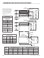
DIMENSIONS AND SPECIFICATIONS GPD SERIES
3"
[76mm]
7-15/16"
[201mm]
12-1/2"
[318mm]
45-1/4"
[1149mm]
8"
[203mm]
7-21/32"
[195mm]
3/4" N.P.T.
[19 mm]
GAS INLET
14-1/2"
[368mm]
23-3/8"
[594mm]
24-21/32"
[626mm]
28-1/2"
[724mm]
DECK
36-1/2"
[927mm]
REAR & SIDE
GAS INLET
REAR & SIDE
GAS INLET
DIA 6"
[152 mm]
74-1/32"
[1880mm]
23-3/8"
[594mm]
51-7/8"
[1318mm]
DECK
31"
[787mm]
24-21/32"
[626mm]
45"
[1143mm]
DECK
53"
[1346mm]
67-5/32"
[1705mm]
DIA 6"
[152 mm]
Installation Notes:
Non-Combustible &
Combustible Wall
Clearances
Sides Back
1” (25mm) 6” (152mm)
Entry Clearance:
Crated Uncrated
35”
(889mm)
26”
(660mm)
Manifold
Operating Pressure:
Natural Propane
6” WC
(15mbar)
10” WC
(25mbar)
INPUT SPECIFICATIONS
Natural Or Propane
MODEL BTU/HR KW
GAS
INLET
GPD48 96,000 28.1 3/4" N.P.T.
GPD60 122,000 35.7 3/4" N.P.T.
GPD48-2 192,000 56.2 1" N.P.T.
GPD60-2 244,000 71.4 1" N.P.T.
Ratings shown are for natural gas
installations up to 2000 feet (610m)
above sea level. BTU input ratings
must be de-rated for high altitude
installations. Specify altitude of
product if over 2000 feet (610m).
This product is not approved for
residential use.
MODEL
NUMBER
Interior Dimensions: In (mm) Exterior Dimensions In (mm)
W H D W H (w/NSF legs) D
GPD48 48 (1220) 8 (203) 36 (914) 63 (1600) 52-3/4 (1340) 45-1/4 (1149)
GPD60 60 (1524) 8 (203) 36 (914) 75 (1905) 52-3/4 (1340) 45-1/4 (1149)
GPD48-2 48 (1220) 8 (203) 36 (914) 63 (1600) 62-1/2 (1588) 45-1/4 (1149)
GPD60-2 60 (1524) 8 (203) 36 (914) 75 (1905) 62-1/2 (1588) 45-1/4 (1149)

Part # 1844063 Rev 1 (01/30/07) Page 5
INSTALLATION
1. Damage Check: check carton or crate for possible
damage incurred in shipping. After carefully uncrating,
check for “concealed” damage. Report any damage
immediately to your carrier.
2. The correct type of gas for which the unit was
manufactured is noted on the rating plate, and this type
of gas must be used.
3. The gas pressure must be checked when the unit is
installed, to ensure that the unit gas pressure is the same
as specied on the rating plate. If necessary pressure
adjustments can be made at the pressure regulator,
supplied on each unit.
4. Have a qualied gas technician check the gas pressure
to make certain that existing gas facilities (meter, piping,
etc.) will deliver the BTU’s of gas required at the unit with
no more than ½” water column pressure drop. When
checking pressure, be certain that all the equipment on
same gas line is turned to the “ON” position.
5. Make certain that the new piping, joints and connections
have been made in a clean manner and have been
purged, so that the piping compound, chips, etc will not
clog pilots, valves and / or controls. Use pipe joint sealant
that is certied for use with LP gas.
6. WARNING; check gas connections for leaks, using soap
solution or similar means. DO NOT CHECK WITH AN OPEN
FLAME.
Rating Plate
All burner-input ratings are shown on the serial plate located
on the right side panel of the appliance.
When corresponding with the factory or your local
authorized factory service center regarding service problems
or replacement parts, be sure to refer to the particular unit
by the correct model number (including the prex and sux
letters and numbers) and the warranty serial number. The
rating plate axed to the unit contains this information.
We suggest installation, maintenance and repairs should be
performed by your local authorized service agency listed in
your information manual pamphlet.
In the event you have any questions concerning the
installation, use, care or service of the product, write or call
our Product Service Department.
This product must be installed by professional personnel as
specied. Garland/U.S. Range products are not approved or
authorized for home or residential use, but are intended for
commercial applications only. Garland / U.S. Range will not
provide service, warranty, maintenance or support of any
kind other than in commercial applications.
Gas Connections
The inlet manifold size for connection to the main gas supply
is (1) 3/4” NPT inlet for each deck.
The importance of proper installation of Commercial
Gas cooking Equipment cannot be over stressed. Proper
performance of the equipment is dependent, in great part,
on the compliance of the installation with the manufacturer’s
specications. Installation must conform to local codes with
the Nation fuel code, ANSI Z223.1, Natural Gas Installation
code, CAN/CGA-B149.1, or the Propane Installation code,
CAN/CGA-B149.2, as applicable, including:
1. The appliance and its individual shut-o valve must be
disconnected from the gas supply piping system during
any pressure testing of that system at test pressures in
excess of 1/2 psi (3.45 kPa).
2. The appliance must be isolated from the gas supply
piping system by closing its individual manual shut-o
valve during any pressure testing of the gas supply piping
system at test pressures equal to or less than 1/2 psi
(3.45 kPa).
Before assembly and connections, check gas supply.
A. The type of gas for which the unit is equipped is stamped
on the data plate located behind lower front panel.
Connect a unit stamped “NAT” only to natural gas;
connect those stamped “PRO” only to propane gas.
B. If it is a new installation, have gas authorities check meter
size and piping to assure that the unit is supplied with
sucient amount of gas pressure required to operate the
unit.
C. If it is additional or replacement equipment, have gas
authorities check pressure to make certain that existing
meter and piping will supply fuel at the unit with not
more than ½” water column pressure drop.
NOTE: When checking pressure be sure that all other
equipment on the same gas line is on. A pressure regulator is
supplied with GARLAND Pizza Ovens. Regulator is preset to
deliver gas at pressure shown on the rating plate.

Part # 1844063 Rev 1 (01/30/07)Page 6
Installation Clearances
Minimum clearance for combustible and Non-Combustible
Construction : 1” (25mm) sides and 6” (152mm) rear. Suitable
for installation on combustible oors. Legs must be installed.
Preparation
1. Carefully remove unit from carton or crate. Burner tie
wires and other packing material should be removed
from units. On stainless steel units, the protective
material covering the stainless steel should be removed
immediately after the unit is installed.
2. This unit must be mounted on the factory-supplied legs
when installed. Refer to section titled LEG INSTALLATION
for details.
3. Provide adequate clearances for proper operation and
servicing of the appliance.
4. For your safety: keep the appliance area free and clear
from combustibles.
5. These units must be installed under an adequate
ventilation system. Refer to sections titled “Ventilation”
and “Air Supply” for further instructions.
Ventilation
This appliance must be installed in a location in which the
facilities for ventilation permit satisfactory combustion of gas
and proper venting. Proper ventilation is imperative for good
operation of the appliance. The ideal method of ventilating
equipment is the use of a properly designed ventilating
canopy, which should extend at least 6”/152mm beyond all
sides of the appliance (except against the wall if the canopy
is a wall installation). This is usually part of a mechanical
exhaust system.
Air Supply
1. It is necessary that sucient room air ingress be allowed
to compensate for the amount of air removed by any
ventilating system. Otherwise a subnormal atmospheric
pressure will occur, aecting the appliance operation
adversely and causing undesirable working conditions.
2. Appliances shall be located so as not to interfere with
proper circulation of air within the conned space. All gas
burners and pilots require sucient air to operate.
3. Large objects should not be placed in front of the
appliance, which might obstruct the airow through
the front. Do not obstruct the ow of combustion and
ventilation air.
4. Do not permit fans to blow directly at the appliance, and
wherever possible, avoid open windows adjacent to the
appliance sides and back; also wall type fans which create
air cross-currents within the room.
Installing Under Ventilation Canopy:
Too strong a pull through the exhaust system will pull heat
out of the oven too rapidly and cause uneven baking (strong
bottoms and light tops).
All ovens, operating under a ventilating canopy should be
equipped with a canopy ue diverter assembly (supplied to
oset too strong a pull.
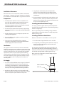
Installing with Direct Ventilation
Wherever a direct ue is unavoidable, it is necessary that:
1. The draft diverter shipped with the oven is installed.
2. An adequately sized draft regulator (barometric damper)
must be installed in the ue line as close to the oven
connection as possible.
An adequately sized prefabricated metal vent should rise at
least 10 feet (3m) above the roof of the building in which it is
installed, or 10 feet (3m) above any proximate higher structure,
and should be equipped with a well designed vent cap.
Never, under any circumstances, install a damper or place
steel wool in an oven ue.
DRAFT DIVERTER
FLUE CAP
INSTALLATION Continued

Part # 1844063 Rev 1 (01/30/07) Page 7
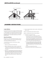
INSTALLATION continued
Termination Less than 10 feet (3 meters) from ridge Termination More than 10 feet (3 meters) from ridge
Less than 10 feet (3 meters)
More than 10' (3 meters)
2' (60cm)
Min.
3' (90cm) Min.
3' (90cm) Min.
ASSEMBLY INSTRUCTIONS
Leg Installation
On single deck units, tip oven section units back. On double-
deck units, tip lower oven section ONLY on its back. Each leg
is secured with four 3/8” (16mm) hex head bolts, threaded
into nuts located on the underside of the base angle. When
both front legs are installed, lift and block up rear of unit.
Install rear legs.
Hearth Installation
NOTE: Because of the weight of the hearth plates, be very
careful to avoid injury to yourself and to shelf joint edges,
when sliding shelf halves into the oven.
To install hearth core plates or steel hearth assembly,
proceed as follows:
1. Slide the wooden frame out of the oven.
2. Before installing the hearth core plates or steel hearth
assembly, be sure that the bottom heat deectors are
properly positioned with the treaded side (bumps) in the
up position.
3. If the oven is supplied with a steel hearth assembly, place
the hearth spacers (with the at side in the up position)
on the extreme left and right sides of the oven resting on
the heat deectors. Making sure the hearth spacers are
not disturbed, slide the steel hearth assembly into the
oven.
4. If oven is supplied with hearth core plates, slide the plates
into the oven.
GPD-48 is supplied with (2) two hearth core plates.
GPD-60 is supplied with (3) three hearth core plates.
5. Installation instruction for Hearth.
a. Place a screwdriver, or a similar prying device,
between the core plate and hearth frame support,
(being careful not to chip the core plate) then place
two spacer clips (PN G03086-1-9) between the core
plate and the hearth frame support. (See instructions
sheet –PN 1917401) 6” from front & 6” from rear.
b. Place a screwdriver between the back of the right
core plate and hearth frame support. Pry the core
plate forward, away from the hearth support and
place a clip within the space centered on each core
plate.
c. Repeat step 2 for the left core plate
d. Repeat step 3 for the center core plate for 60” unit.

Part # 1844063 Rev 1 (01/30/07)Page 8
ASSEMBLY INSTRUCTIONS Continued
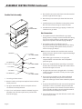
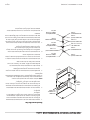
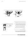
Double Deck Assembly
1 x 4
LUMBER
FLUE
CONNECTOR
FIGURE 1
3/4 NIPPLE
3/4" COUPLING
3/4" x 3/4" x 1" TEE
6 1/2" NIPPLE
3/4" NIPPLE
3/4" COUPLING
1" NPT
90° STREET ELBOW
5 3/4" NIPPLE
3/4" UNION
3/4" NPT
90° STREET ELBOW
3/4" NPT
90° STREET ELBOW
1 Secure legs to lower section
2. Remove stainless steel top trim strip from lower unit if not
already removed.
3. Tip upper unit backward. Remove vent patch at lower
rear if not if not already removed.
4. Place 1” x 4” x 65” (25mm x 100mm x 1650mm) long piece
of lumber across the rear top of oven to prevent stacks
from misarranging.
5. Place the ue connector on the lower unit with extended
part to the right of the unit. (Fig 1)
6. Raise the top oven section up and onto the lower oven
section.
7. Carefully remove piece of lumber ensuring lower section
ue connector inserts into upper section vent hole.
8. Assemble the interconnecting gas piping as shown and
connect to rear gas inlets.
Gas Connection
1. The appliance must be isolated from the gas supply
piping system by closing its manual shut-o valve during
any pressure testing of the gas supply piping system at
test pressure equal to or less that 1/2 psig. (3.45 kpa.).
2. The appliance and its shut o valve must be
disconnected from the gas supply piping system during
any pressure testing of that system at test pressures in
excess of 1/2 psig. (3.45 kpa.).
NOTE: The ovens should not be installed on the same line
with space heaters, broilers or other equipment with high
intermittent demand.
3. When making gas connections, uses a pipe joint
compound that is resistant to the action of liqueed
petroleum gases.
4. Each oven is supplied with two possible gas connection
locations. One is located on the right side and the other is
located on the right rear corner.
5. The right side connection is plugged with a 3/4 counter
sunken plug. If this connection is used, you must cap the
rear connection.
6. The gas pressure regulator is part of the combination
valve and is adjusted to yield a pressure of 6.0” water
column for natural gas and 10” water column for propane
gas.
7. A separate shut-o valve for each oven must be provided.
It should be as close as possible to the place where the
gas line goes into the oven. It must be located so that it is
easily accessible. A handle or wrench should be chained
to the valve where it will always be at hand.
8. For a stack of two ovens, two shut-o valves, one for each
oven must be provided.

Part # 1844063 Rev 1 (01/30/07) Page 9
ADJUSTMENTS
Gas Pressure Adjustments
All GPD Series ovens are equipped with xed orices and
cannot be adjusted for gas ow: If necessary, pressure
adjustments can be made at the pressure regulator (located
on the combination gas valve).
A pressure tap is supplied with the unit and it is installed
on the manifold, downstream of the main valve. The gas
pressure must be checked when the unit is installed, to
ensure that the unit gas pressure is the same as specied on
the rating plate.
IMPORTANT:
All gas burners and pilots need sufficient
air to operate and large objects should not
be placed in front of this oven, which would
obstruct the airflow through the front.
Objects should not be placed on main rear of
oven while in use.
Flame & Air Mixture Adjustment
After the pilot burner is ignited, when heat is desired, turn
gas cock dial to “ON” position and set the thermostat dial
to the desired temperature. The oven burner ame should
always have a blue appearance. This indicates a good mixture
of air and gas. When using LP gas the ame will have a blue
yellow appearance. Follow steps 1 thru 4 to adjust the ame
for good quality.
1. Loosen the small knurled locking disk.
2. Turn the large adjusting disk towards the air mixture
throat to reduce the opening. This restricts the amount of
air, causing the ame to turn yellow.
3. Turn the adjusting disk gradually out, away from the air
mixer throat, allowing more air into the air mixer until the
yellow disappears and a sharp blue ame appears.
4. When the ame turns blue and spreads out, turn the
locking disk tight against the adjusting disk. There may
be intermittent yellow-orange ame noticed. This is
caused by dust particles burning in the Flame. Should the
burners fail to light, check to see if there is a problem with
any or all of the following.
A. The gas supply: If there are other gas appliances on the
same supply line, shut them o temporarily and see if
the ame comes back on, or if it uctuates as other gas
appliances are turned on and o. If so, it would indicate
overloading of the gas supply or a faulty gas pressure
regulator. You should contact a qualied service agency
or the local gas company to check the gas supply.
B. Dirty burner orice or ports: With the oven cold, use a
thin wire to check that the spud orice (nozzle) is clear. If
necessary, loosen and remove the spud. Be careful when
cleaning not to enlarge the hole. Then, using a wire or
thin nail, clear the burner ports of carbon deposits or
other restrictions.
Periodically, after breaking the ovens in, check the burner
ame and readjust the air mixture if needed. Black soot on the
oven doors or in the burner compartment may indicate that
not enough air is mixing with the gas. If this case back o the
air adjustment disk until the proper ame and color is set.
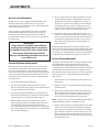
By-Pass Flame Adjustment
The by-pass in the thermostat is a small gas supply through
the control that is independent of the dial setting. It is
controlled strictly by the Adjusting Screw. This small gas
supply maintains a minimum ame or the burner(s), helping
to maintain the heat in the oven and assisting in recovery.
This adjustment is best done when the oven is being heated
for the day’s business. To adjust the by-pass ame follow
steps 1 thru 4.
1. Turn the oven on and set the thermostat to the desired
temperature.
2. Allow the oven to pre-heat until the burner ame begins
to throttle down.
3. At this point, turn the thermostat dial all the way down.
This ensures that the thermostat is in the by-pass mode.
There should now be a small steady ame remaining
across the burner without ickering or going out.
NOTE: It may be necessary to turn the thermostat back up to
relight the burner(s) if there is not ame present.
4. Using a small screwdriver, reach through the access hold
on the control panel to the left of the thermostat knob.
Turn the by-pass adjustment screw to raise or lower the
by-pass ame as required. Counter-clockwise raises the
ame, clockwise lowers the ame. Take care not to turn
the screw out too far as that will allow gas to leak around
the adjustment screw.

Part # 1844063 Rev 1 (01/30/07)Page 10
Calibration
1. Field calibration is seldom necessary and should not
be attempted unless experience with cooking results
denitely proves that the control is not maintaining the
temperature to which the dial is set.
2. Place the thermocouple of the test instrument or
reliable mercury thermometer in the center of the oven
approximately one or two inches (25mm – 50mm) above
the hearth. Do not place the thermocouple directly in
contact with the hearth.
3. Set the thermostat temperature dial to 500 degrees
F (260 degrees C) and allow the oven temperature to
stabilize. The thermostat must be allowed to cycle twice
before taking a test reading.
4. Check the temperature when the burner just cycles
o after the second cycle, compare the reading of
thermocouple or thermometer with thermostat setting.
5. If the two do not agree (plus or minus 15 degrees F
(8 degrees C)), carefully remove the thermostat dial, not
disturbing dial settings.
6. Hold calibration plate and loosen the two calibration
screws until the plate can be moved independently of the
control.
7. Turn calibration plate so that the instrument of
thermometer reading is in line with the indicator mark.
Hold plate and tighten screws rmly.
8. Replace dial.
9. NOTE: If the above adjustment is prevented by the two
loosened calibration lock screws being in contact with
the ends of the screw clearance plate to the proper
location, reassembly screws in the other tapped holes
designed for them.
NOTE: NO ATTEMPT TO RECALIBRATE THE OVEN CONTROL
SHOULD BE MADE WITHIN THE WARRANTY PERIOD IF THE
TEMPERATURE IS WITHIN ±20 DEGREES FAHRENHEIT OF
THE DIAL SETTING. RECALIBRATION SHOULD BE MADE
IF THE CONTROL IS OUT MORE THAN ±20 DEGREES
FAHRENHEIT AND LESS THAN ±50 DEGREES FAHRENHEIT.
IF THE CONTROL IS OUT MORE THAN 50 DEGREES
FAHRENHEIT FROM THE DIAL SETTING, THE CONTROL WILL
BE REPLACED UNDER WARRANTY, (WITHIN THE WARRANTY
PERIOD).
Flame Diverters
Flame diverters distribute the heat evenly below the deck.
They must be in good condition and properly placed in
the burner chamber in order to be eective. Damaged or
improperly installed ame diverters adversely aect the
oven performance. Check them periodically and replace as
needed. Make sure that the “V” shaped diverters are pushed
all the way to the back of the oven as far as they will go.
ADJUSTMENTS Continued
2. Many of the parts used in the oven have a thin protective
oil covering. This oil should be burned o before the
oven is used for the production of food products. It is
normal for the unit to smoke while burning o excess
oil. Washing the deck of the oven with a damp clean
cloth and mild soap solution will remove some of the
protective oil coating.
Break-In
1. Once the equipment has been installed and tested by
qualied professional personnel, the oven is ready for
operation.
OPERATION

Part # 1844063 Rev 1 (01/30/07) Page 11
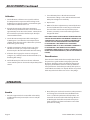
OPERATION Continued
CLEANING
Oven Exterior
Painted Surfaces should be cleaned when cool, using a mild
soap and warm water solution on a sponge or soft clean
cloth. Rinse and dry thoroughly with a soft clean cloth.
Stainless Steel Surfaces usually respond to cleaning as noted
above. Stubborn stains or heat tint may require the use of
a commercial type cleaner, such as Penny Brite or stainless
steel pad. Always rub in the direction of the polished lines.
Rinse thoroughly with fresh water and wipe dry.
Oven Interior
Aluminized Steel Surfaces Should be cleaned with a damp
soft cloth and mild household detergent.
Core Plates
CAUTION: The use of water to cool down or clean core
plates will void warranty.
To clean core plates, set thermostat dial to 550 degrees F
(288 degrees C) at the end of the cooking day and allow
thermostat to cycle for one hour. When the oven has cooled,
cooking residue will be carbonized and can be removed
by sweeping with a sti brush. Stubborn residue can be
loosened with a scraper.
3. Select a temperature of 300 degrees F (150 degrees C)
and turn the gas cock dial to the ON position.
4. Allow the oven to warm to 300 degrees F (150
degrees C) and keep it there for FIVE HOURS, or at least
until all smoke and fumes have disappeared. The smoke
and fumes are from moisture in the deck and insulation
and a light coat of oil.
5. Turn the thermostat knob to between 475 degrees F (250
degrees C). Allow the oven to warm up to your selected
temperature for 1 to 1 1/2 hours.
6. When the oven has reached the selected temperature,
experiment until you get the feel of the oven and the
speed of the bake. In case of some initial unevenness in
the baking, have patience for a few days until the oven
cures.
Lighting/Shutdown Instructions
1. Open control panel door located on right hand side of
unit. To access combination gas control.
2. Turn gas cock on combination control to the “OFF”
position. Wait 5 minutes.
3. Turn gas cock on combination control to the “PILOT”
position.
4. Depress gas cock and light pilot burner.
5. Hold gas cock depressed for one minute after pilot has
been ignited, then release. Pilot should continue to burn.
6. If pilot does not continue to burn after releasing gas cock,
repeat steps 2 thru 5 or have a qualied serviceman check
the system. Do not allow anyone else to attempt repairs.
7. Once pilot is lit, turn gas cock to the “ON” position. It is not
necessary to repeat lighting procedure unless the pilot is
extinguished by any cause.
8. To shut down unit, turn gas cock on combination control
to the “OFF” position

Part # 1844063 Rev 1 (01/30/07)Page 12
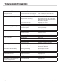
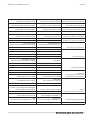
Problem Causes Solutions
Hot Spots in Deck Flame diverters not installed properly Push all the way to the back of oven
Flame diverters warped or damaged May need replacing
Bottoms cook before top Deposit on deck Clean deck
Low production oven idling Turn temperature up after loading pizza.
Make sure to turn the temperature down
after bake is compete
By-pass ame too high Adjust by-pass ame
Improper damper position Adjust dampers
Bottoms become light during
periods of heavy production
Improper damper position Close dampers
Placement of pizza Change placement
By-pass ame low Increase by-pass ame
Color overall dark High temperature Lower temperature
Pizza left in too long Reduce bake time
By-pass ame high Reduce by-pass ame
Thermostat Check actual temperature; call for service
Color overall light Short bake time Bake longer
Lower temperature Increase temperature
Dough Check dough for freshness
Pre-heat time short Allow for adequate pre-heating
Top color light Damper closed Open damper
Oven idles during slow periods Increase temperature to bake, reduce again
when bake is nished
Burner ame yellow/soft/lazy Not enough air mixing Open (adjust) air shutter
Low gas pressure Adjust pressure
Flame lifts o burner ports Too much air mixed with gas Close (adjust) air shutter
Flashes back in burner Gas pressure too high Adjust pressure
Pops excessively when turned o Wrong orice in unit Replace with proper orice
Burner ame too large Unit over gassed or wrong orice Check gas pressure and orice size
Burner ame shuts o when oven
reaches set temperature
By-pass set too low Adjust by-pass
TROUBLESHOOTING GUIDE


Pièce nº 1844063 Rev 1 (01/30/08)Page 14
Problème Causes Solutions
Points chauds dans la section Les dé ecteurs de ammes ne sont pas
bien installés
Pousser complètement jusqu’au fond du
four
Les dé ecteurs de amme sont
déformés ou endommagés
Peut exiger le remplacement
Les fonds cuisent plus vite que les
dessus
Dépôts sur la section Nettoyer la section
Faible production, four au ralenti Augmenter la température après
l’introduction de la pizza. Ne pas oublier de
baisser la température après la cuisson.
Flamme de dérivation trop forte Régler la amme de dérivation
Mauvaise position des volets
d’obturation
Régler les volets d’obturation
Les fonds cuisent moins bien
pendant les périodes de forte
production
Mauvaise position des volets
d’obturation
Fermer les volets d’obturation
Emplacement de la pizza Changer d’emplacement
Flamme de dérivation basse Augmenter la amme de dérivation
Couleur trop sombre Température élevée Abaisser la température
Pizza restée trop longtemps Réduire le temps de cuisson
Flamme de dérivation trop forte Réduire la amme de dérivation
Thermostat Véri er la température réelle; appelerun
technicien d’entretien
Couleur trop claire Temps de cuisson trop court Prolonger la cuisson
Température basse Augmenter la température
Pâte Véri er la fraîcheur de la pâte
Temps de préchau age trop court Laisser le four préchau er correctement
Couleur du dessus trop claire Volet d’obturation fermé Ouvrir le volet d’obturateur
Le four se met au ralenti pendant les
périodes d’inactivité
Augmenter la température pour lacuisson
et l’abaisser ensuite
Flamme des brûleurs jaune/faible/
peu puissante
Pas assez d’air dans le mélange Ouvrir (régler) l’obturateur d’air
Pression de gaz trop basse Régler la pression
La amme se détache des ori ces
des brûleurs
Trop d’air dans le mélange Fermer (régler) l’obturateur d’air
Retours de amme dans le brûleur Pression de gaz trop élevée Régler la pression
Claquement excessif à la fermeture
du gaz
Erreur d’ori ce dans l’appareil Remplacer par une ori ce correct
Flamme du brûleur trop large Alimentation excessive en gaz ou
erreur d’ori ce
Véri er la pression du gaz et la taille de
l’ori ce
Flamme du brûleur s’éteint lorsque
la température est atteinte
Réglage de amme de dérivation
trop bas
Régler la amme de dérivation
GUIDE DE DÉPANNAGE

Pièce nº 1844063 Rev 1 (01/30/08) Page 13
NETTOYAGE
Extérieur Du Four
Les surfaces peintes doivent être nettoyées à froid, en
utilisant une solution de savon doux et d’eau tiède sur un
chi on propre ou une éponge. Rincer et bien assécher avec
un chi on doux et propre.
Les surfaces en acier inoxydable sont généralement traitées
de la façon expliquée plus haut. Les taches rebelles ou les
traces de chaud peuvent exiger l’utilisation d’un produit de
nettoyage commercial tels que : Penny-Brite ou de tampons
d’acier inoxydable. Il faut toujours frotter dans le sens des
lignes de polissage. Bien rincer à l’eau claire et assécher.
Intérieur du four
Les surfaces en acier aluminisé doivent être nettoyées avec
un chi on doux humide et du détergent ménager doux.
Plaques de sole
ATTENTION : L’utilisation d’eau pour refroidir ou nettoyer les
plaques de sole annule la garantie.
Pour le nettoyage des plaques de sole, régler le thermostat à
550 degrés F (288 degrés C) à la n de la journée de travail et
laisser le thermostat accomplir son cycle pendant une heure.
Après le refroidissement du four, les résidus de cuisson seront
carbonisés et faciles à retirer à l’aide d’une brosse dure. Les
résidus tenaces peuvent être délogés à l’aide d’un grattoir.

Pièce nº 1844063 Rev 1 (01/30/08)Page 12
FONCTIONNEMENT
Rodage
1. Une fois l’installation de l’appareil par le personnel
professionnel quali é terminée, le four est prêt à
fonctionner.
2. De nombreuses pièces du four sont couverte d’huile de
protection. Cette huile doit être brûlée avant d’utiliser
le four pour la préparation de denrées alimentaires. Il
est normal que l’appareil fume pendant l’élimination de
l’huile de protection. Il est également possible d’enlever
une partie de cette couche d’huile de protection en
lavant l’appareil à l’aide d’un chi on propre humecté
d’eau savonneuse.
3. Sélectionner une température de 300 degrés F (150
degrés C) et placer le robinet de gaz en position ON.
4. Laisser le four atteindre la température de 300 degrés
F (150 degrés C) et le maintenir à cette température
pendant CINQ HEURES ou au moins jusqu’à ce que
toutes les émanations de fumée soient terminées. Ces
émanations proviennent de humidité à l’intérieur du four
et de la ne couche d’huile de protection.
5. Placer le bouton du thermostat vers la marque de 475
degrés F (250 degrés C). Laisser le four chau er pour
atteindre la température sélectionnée pendant 1 heure à
1 heure 1/2.
6. Lorsque le four a atteint la température sélectionnée, faire
quelques expériences pratiques pour se familiariser avec
le four et les vitesses de cuisson. Si certaines inégalités de
cuisson apparaissent, il faut avoir la patience d’attendre
quelques jours jusqu’à ce que le four sèche.
Instructions D’allumage Et D’arrêt
1. Ouvrir la porte du panneau de commande située sur
le coté droit de l’appareil pour accéder à la commande
combinée de gaz.
2. Tourner le robinet de gaz de la commande combinée en
position « OFF ». Attendre 5 minutes.
3. Tourner le robinet de la commande combinée en position
« PILOT ».
4. Appuyer sur le robinet de gaz et allumer la veilleuse.
5. Maintenir le robinet enfoncé pendant 1 minute après
l’allumage de la veilleuse et le relâcher ensuite. La
veilleuse devrait rester allumée.
6. Si la veilleuse ne reste pas allumée après avoir relâché le
robinet de gaz, répéter les étapes 2 à 5 ou faire appel à
un technicien quali é pour véri er le système. Ne laisser
personne d’autre tenter de dépanner l’appareil.
7. Une fois que la veilleuse allumée, tourner le robinet de
gaz en position « ON ». Il n’est pas nécessaire de répéter la
procédure d’allumage, sauf si la veilleuse s’éteint.
8. Pour arrêter l’appareil, mettre le robinet de gaz de la
commande combinée en position « OFF ».

Pièce nº 1844063 Rev 1 (01/30/08) Page 11
4. Passer un petit tournevis par le trou d’accès du panneau
de commande à gauche du bouton du thermostat.
Tourner la vis du réglage de dérivation pour augmenter
ou diminuer la amme de dérivation, selon le cas. Le
fait de tourner dans le sens contraire des aiguilles d’une
montre augmente la amme, le fait de tourner dans le
sens des aiguilles d’une montre la diminue. Ne pas trop
desserrer la vis, car cela peut provoquer des fuites de gaz
autour de la vis de réglage.
Étalonnage
1. L’étalonnage sur place est rarement nécessaire et avant
de le faire il convient de s’assurer que les résultats
de cuisson prouvent que le four ne maintient pas la
température sélectionnée sur le cadran.
2. Placer le thermocouple de l’appareil d’essai ou un bon
thermomètre au mercure au milieu du four à u ou deux
pouces (25 mm - 50 mm) au-dessus de la sole. Ne pas
placer le thermocouple directement en contact avec la
sole.
3. Régler le bouton du thermostat sur 500 degrés F (260
degrés C) et laisser la température du four se stabiliser.
Laisser le cycle du thermostat s’accomplir deux fois avant
de procéder à la lecture du résultat de l’essai.
4. Véri er la température dès que le brûleur s’arrête après
avoir e ectué le second cycle, et comparer la lecture du
thermocouple ou du thermomètre avec le réglage du
thermostat.
5. En cas de désaccord entre les indications (plus ou moins
15 degrés F (8 degrés C)), retirer soigneusement le cadran
du thermostat, sans modi er le réglage.
6 Maintenir la plaque d’étalonnage et desserrer les deux vis
d’étalonnage jusqu’à ce qu’on puisse bouger la plaque
indépendamment de la commande.
7. Tourner la plaque d’étalonnage de façon à ce l’indication
du thermomètre soit conforme à la marque de
l’indicateur. Maintenir la plaque et bien serrer les vis.
8. Remettre le bouton en place.
9. NOTE: S’il n’est pas possible d’e ectuer le réglage
ci-dessus parce que les vis de blocage d’étalonnage
desserrées sont en contact avec les extrémités de la
plaque de dégagement des vis, remonter les vis dans les
autres trous letés conçus pour elles.
NOTE: NE PAS TENTER D’ÉTALONNER DE NOUVEAU
LE FOUR PENDANT LA DURÉE DE LA GARANTIE SI
LA TEMPÉRATURE DEMEURE DANS UNE PLAGE DE +
20 DEGRÉS FAHRENHEIT DU RÉGLAGE DU CADRAN.
L’ÉTALONNAGE DOIT ÊTRE EFFECTUÉ SI LA DIFFÉRENCE
EST SUPÉRIEURE À ±20 DEGRÉS FAHRENHEIT ET
INFÉRIEURE À ±50 DEGRÉS FAHRENHEIT. SI LA
COMMANDE EST DÉRÉGLÉE DE PLUS DE 50 DEGRÉS
FAHRENHEIT PAR RAPPORT AU CADRAN, LA COMMANDE
SERA REMPLACÉE AU TITRE DE LA GARANTIE (PENDANT
LA DURÉE DE LA PÉRIODE DE GARANTIE).
Dé ecteurs De Flammes
Les dé ecteurs de ammes répartissent également la
chaleur sous la section. Ils doivent être en bon état et bien
placés dans la chambre de combustion pour être e caces.
Les dé ecteurs endommagés ou mal installés a ectent
négativement le fonctionnement du four. Les véri er
périodiquement et les remplacer si nécessaire. S’assurer que
les dé ecteurs en forme de « V » sont complètement poussés
vers l’arrière du four jusqu’à la butée.
RÉGLAGES suite

Pièce nº 1844063 Rev 1 (01/30/08)Page 10
RÉGLAGES
Réglages de pression du gaz
Tous les fours de la série GPD sont équipés d’ori ces xes
et le débit de gaz ne peut pas être réglé. Si nécessaire, les
réglages de pression peuvent être faits au régulateur de
pression (situé sur la valve combinée de gaz).
Un robinet de pression est fourni avec l’appareil. Il est installé
sur le collecteur, en aval du robinet principal. La pression de
gaz doit être véri ée lors de l’installation de l’appareil a n de
s’assurer qu’elle est identique à celle spéci ée sur la plaque
signalétique.
IMPORTANT :
Tous les brûleurs à gaz et les veilleuses ont
besoin de suffisamment d’air pour
fonctionner. Éviter de placer
des objets de grande taille devant le four,
car de tels objets risquent d’obstruer
le débit d’air vers l’avant du four.
On ne devra pas placer d’objets sur l’arrièr
principal du four pendant qu’il est utilisé.
Réglages De Flamme Et Du Mélange D’air
Une fois que la veilleuse est allumée et si on a besoin de
chaleur, placer le cadran du robinet de gaz sur « ON » et
régler le cadran du thermostat à la température désirée.
La amme du brûleur du four doit toujours être de couleur
bleue. Cette couleur indique un bon mélange d’air et de gaz.
Lorsque l’on utilise le gaz de pétrole liqué é, la amme est
de couleur bleue-jaune. Suivre les étapes 1 à 4 pour régler la
amme.
1. Desserrer le petit disque de blocage moleté .
2. Tourner le grand disque de réglage vers la gorge de
mélange d’air pour réduire l’ouverture. Cette action limite
la quantité d’air et la amme devient jaune.
3. En dévissant graduellement le disque de réglage, et en
l’éloignant de la gorge de mélange d’air, on augmente
la quantité d’air dans le mélange jusqu’à ce que le jaune
disparaisse et qu’on obtienne une amme bleu vif.
4. Lorsque la amme devient bleue et qu’elle s’étale, tourner
le disque de blocage contre le disque de réglage. Il se
peut que de temps en temps, une lueur jaune-orange
intermittente apparaisse dans la amme. Ceci est causé
par des particules de poussière brûlant dans la amme. Si
les brûleurs ne s’allument pas, véri er les points suivants
pouvant en être la cause.
A. Alimentation en gaz : S’il existe d’autres équipements
fonctionnant au gaz sur la même conduite, les fermer
provisoirement et voir si la amme s’allume et si son
intensité change chaque fois que d’autres appareils
sont allumés ou éteints. Dans de tels cas, il s’agit
probablement d’une surcharge de la conduite ou d’un
régulateur de pression défectueux. Contacter une
entreprise d’entretien quali ée ou la compagnie locale de
gaz pour faire véri er l’alimentation.
B. Ouverture ou ori ces de brûleurs sales : Lorsque le four
est froid, utiliser un l métallique n pour s’assurer que
l’ori ce d’injecteur (gicleur) est propre. Si nécessaire,
desserrer et retirer l’injecteur.Faire attention de ne pas
agrandir le trou pendant le nettoyage. Ensuite, à l’aide
d’un l métallique ou d’un clou n, nettoyer les ori ces
des brûleurs pour en enlever les dépôts de carbone ou
d’autres matières.
Après le rodage du four, véri er périodiquement la amme
des brûleurs et réajuster le mélange au besoin. De la suie
noire sur les portes du four ou dans le compartiment des
brûleurs peuvent indiquer que la quantité d’air dans le gaz
est insu sante. Dans de tels cas, reculer le disque de réglage
d’air jusqu’à ce que la bonne couleur de amme apparaisse.
Réglage De La Flamme De Dérivation:
La dérivation dans le thermostat est une alimentation en
gaz arrivant à la commande indépendamment du réglage
du cadran. Cette alimentation est commandée par la vis
de réglage. Cette petite alimentation de gaz maintient
une amme minimale dans le(s) brûleur(s) et permet de
maintenir le four chaud et de faciliter son réchau age. La
meilleure moment pour la régler est lorsque l’on met le four
en chau e pour la journée de travail. Pour régler la amme
de dérivation, suivre les étapes 1 à 4.
1 Allumer le four et régler le thermostat à la température
désirée.
2. Laisser le four préchau er jusqu’à ce que la amme
commence à baisser.
3. À ce moment-là, tourner le cadran du thermostat
complètement vers le bas. Ceci fait passer le thermostat
est en mode de dérivation. Il doit y avoir une petit amme
stable sur le brûleur qui ne clignote pas et reste allumée.
NOTE: Il peut être nécessaire d’augmenter le réglage du
thermostat pour rallumer le(s) brûleur(s) s’il n’y a pas de
amme.

Pièce nº 1844063 Rev 1 (01/30/08) Page 9
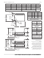
INSTRUCTIONS D’ASSEMBLAGE suite
PIÈCE
DE BOIS
1 X 4
Figure 1
RACCORD
DE CONDUIT
DE FUMÉE
RACCORD FILETÉ
3/4 PO
ACCOUPLEMENT
3/4 PO
RACCORD EN
T 3/4 X 3/4 X 1 PO
RACCORD FILETÉ
6 1/2 PO
RACCORD FILETÉ
3/4 PO
ACCOUPLEMENT
3/4 PO
COUDE MÂLE ET
FEMELLE 1 PO
NPT 90°
RACCORD FILETÉ
5 3/4 PO
RACCORD UNION
3/4 PO
COUDE MÂLE ET
FEMELLE 3/4 PO
NPT 90°
COUDE MÂLE ET
FEMELLE 3/4 PO
NPT 90°
Branchement De Gaz:
1. L’appareil doit être isolé de la canalisation d’alimentation
de gaz par un robinet d’arrêt manuel pendant tout essai
de pression du système de canalisations d’alimentation
lorsque les pressions d’essai sont égales ou inférieures à
1/2 lb/po
2
(3,45 kpa.).
2. L’appareil et son robinet d’arrêt doivent être débranchés
du système de canalisations d’alimentation pendant tout
essai de pression du système lorsque les pressions d’essai
sont supérieures à 1/2 lb/po
2
(3,45 kpa.).
NOTE: Le four ne doit pas être installé sur la même
canalisation que des appareils de chau age, des rôtissoires
ou que d’autres équipements à consommation intermittente
importante.
3. Pour e ectuer les branchements de gaz, utiliser une pâte
à joints résistant aux gaz de pétrole liqué és.
4. Chaque four est équipé de deux emplacements de
branchement possibles, dont l’un se trouve sur le coté
droit et l’autre dans le coin arrière droit.
5. Le branchement de coté droit est équipé d’un bouchon à
carré creux de 3/4 po. Si ce branchement est utilisé, il faut
boucher la connexion arrière.
6. Le régulateur de pression de gaz fait partie de la valve
combinée et est réglé pour produire un pression de 6 po
de colonne d’eau pour le gaz naturel et de
10 po de colonne d’eau pour le propane.
7. Il est nécessaire d’installer un robinet d’arrêt séparé pour
chaque four. Il devra être placé aussi près que possible de
l’endroit d’entrée de la canalisation de gaz dans le four et
devra être facilement accessible. Une poignée ou une clef
doit être enchaînée au robinet pour être disponible à tout
moment.
8. Pour deux fours superposés, il convient d’installer deux
robinets d’arrêt, soit un pour chaque four.
La page est en cours de chargement...
La page est en cours de chargement...
La page est en cours de chargement...
La page est en cours de chargement...
La page est en cours de chargement...
La page est en cours de chargement...
La page est en cours de chargement...
La page est en cours de chargement...
-
 1
1
-
 2
2
-
 3
3
-
 4
4
-
 5
5
-
 6
6
-
 7
7
-
 8
8
-
 9
9
-
 10
10
-
 11
11
-
 12
12
-
 13
13
-
 14
14
-
 15
15
-
 16
16
-
 17
17
-
 18
18
-
 19
19
-
 20
20
-
 21
21
-
 22
22
-
 23
23
-
 24
24
-
 25
25
-
 26
26
-
 27
27
-
 28
28


Garland 36ER33-88 Mode d'emploi
- Catégorie
- Cuisinières
- Taper
- Mode d'emploi
dans d''autres langues
Documents connexes
-
Garland GPD60 Manuel utilisateur
-
-
Garland E20 Series Mode d'emploi
-
-
-
-
-
Garland G60-6R24CS Mode d'emploi
-
Sunfire X60-6R24RS spécification
-
Garland X60-6R24RS Manuel utilisateur