

2
GENERAL SAFETY PRECAUTIONS:
This instruction manual contains important information necessary for the proper assembly and safe
use of this appliance.
Read and understand all warnings and instructions before assembling and using this appliance.
Follow all warnings and instructions when using this appliance.
If instructions or parts are missing contact Artisan™ Professional Grills.
PRÉCAUTIONS GÉNÉRALES DE SÉCURITÉ:
Ce manuel d'instructions contient des informations importantes nécessaires pour le bon assem-
blage et l'utilisation sécurisée de cet appareil.
Lisez et comprenez tous les avertissements et instructions avant d'assembler et d'utiliser cet ap-
pareil.
Suivez tous les avertissements et instructions lors de l'utilisation de cet appareil.
Si vous n'avez pas toutes les instructions ou toutes les pieces, contactez Artisan™ Professional
Grills.
! WARNING
1. DO NOT STORE OR USE GASOLINE OR OTHER
FLAMMABLE LIQUIDS OR VAPORS IN THE VI-
CINITY OF THIS OR ANY OTHER APPLIANCE.
2. AN LP CYLINDER NOT CONNECTED FOR USE
SHALL NOT BE STORED IN THE VICINITY OF
THIS OR ANY OTHER APPLIANCE.
! DANGER
IF YOU SMELL GAS:
1. SHUT OFF GAS TO THE APPLIANCE
2. EXTINGUISH ANY OPEN FLAME.
3. OPEN LID.
4. IF ODOR CONTINUES, KEEP AWAY FROM THE
APPLIANCE AND IMMEDIATELY CALL YOUR
GAS SUPPLIER AND OR FIRE DEPARTMENT.
! AVERTISSEMENT
1. NE PAS ENTREPOSER NI UTILISER DE L’ESSENCE
NI D’AUTRES VAPEURS OU LIQUIDES INFLAMMA-
BLES DANS LE VOISINAGE DE L’APPAREIL, NI DE
TOUT AUTRE APPAREIL.
2. UNE BOUTEILLE DE PROPANE QUI N’EST PAS RAC-
CORDÉE EN VUE DE SON UTILISATION. NE DOIT
PAS ÉTRE ENTREPOSÉE DANS LE VOISINAGE DE
CET APPAREIL OU DE TOUT AUTRE APPAREIL.
! DANGER
S’IL Y A UNE ODEUR DE GAZ:
1. COUPEZ L’ADMISSION DE GAZ DE ‘LAPPARIEL.
2. ÉITENDRE TOUTE FLAME NUE.
3. OUVRIR LE COURVERCLE.
4.
SI L’ODEUR PERSISTE, ÉLOIGNEZ-VOUS DE L’APPA-
REIL ET APPELEZ IMMÉDIATEMENT LE FOURNIS-
SEUR DE GAZ OU LE SERVICE D’INCENDIE
.
3020914
Artisan™ Professional Grills by Alfresco
A division of Superior Equipment Solutions, Inc.
1085 Bixby Drive
City of Industry, CA. 91745
Ph.: (888) 383-8800
Fax: (323) 726-4700
Artisan
™

3
CALIFORNIA PROPOSITION 65 - WARNING
The burning of gas cooking fuel generates toxic by-products, which are on the list of substances which
are known by the State of California to cause cancer or reproductive harm. California law requires
businesses to warn customers of potential exposure to such substances. To minimize exposure to
these substances, always operate this unit according to the use and care manual, ensuring you
provide good ventilation when cooking with gas. This warning is issued pursuant to California Health &
Safety Code Sec. 25249.6
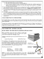
BEFORE USING THE PIZZA OVEN:
Ensure that the Pizza oven has been leak tested. (see page 16 & 17)
Remove any packing material.
Electrical power requirement is 115 VAC - 50/60 Hz. (a GFCI receptacle is recommended for use).
Electric power supply must be plugged-in at all times for oven operation; except during any electrical
maintenance, non-use periods and storage.
F AVERTISSEMENT
PIÈCES ÉLECTRIQUES ET COMPOSANTS.
DÉBRANCHER TOUS LES BLOCS D'ALIMENTA-
TION ET LES PILES AVANT DE LES RÉPARER.
H AVERTISSEMENT
GAZ INFLAMMABLE
DÉBRANCHER TOUS LES GAZ PROPANE OU
GAZ NATUREL DE CET APPAREIL AVANT DE
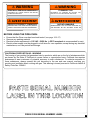
PIZZA OVEN SERIAL NUMBER LABEL
F WARNING
ELECTRICAL PARTS AND COMPONENTS
DISCONNECT ALL POWER SUPPLIES AND BATTER-
IES BEFORE SERVICING.
H WARNING
FLAMMABLE GAS
DISCONNECT ALL PROPANE OR NATURAL GAS
SUPPLIES TO THIS UNIT BEFORE SERVICING.

4
READ THIS CARE AND USE MANUAL CAREFULLY AND COMPLETELY BEFORE USING YOUR
PIZZA OVEN TO REDUCE THE RISK OF FIRE, BURN HAZARD OR OTHER INJURY. KEEP THIS
MANUAL FOR FUTURE REFERENCE.
When properly cared for, your
Artisan™ Pizza Oven will give safe, reliable service for many years.
However, extreme care must be used since the Pizza produces intense heat, which can increase acci-
dent potential. When using this appliance, basic safety practices must be followed, including but not lim-
ited to the following:
Begin by ensuring proper assembly. A qualified technician should perform all other service.
Do not repair or replace any part of the pizza oven unless specifically recommended in this manual.
All other service should be referred to and performed by a qualified technician.
For personal safety, wear proper apparel while cooking.
Loose fitting garments or sleeves should never be worn while using this appliance.
Some synthetic fabrics are highly flammable and should not be worn while cooking.
Never let clothing, pot holders or other flammable materials come in contact with or too close to any
hot surface until it has cooled down sufficiently. Fabrics may ignite and result in personal injury.
Use only dry potholders: moist or damp potholders on hot surfaces may cause personal burns from
steam. Do not use a towel or bulky cloth in place of potholders. Do not let potholders touch hot por-
tions of the pizza oven.
Only certain types of glass, heatproof glass ceramic, earthenware, or other glazed utensils are suita-
ble for oven use. These types of materials may break with sudden temperature changes. Use only on
low or medium heat settings and according to their manufacturer’s directions.
Grease is flammable. Let hot grease cool before attempting to handle it.
Avoid letting grease deposits collect on the hearth stone by cleaning the grease often, but never
while the oven is ON or HOT from recent use.
Do not use aluminum foil to line the hearth stone. This can severely upset temperatures, combustion
and airflow or trap excessive heat in the stone and control area. The result of this can be damaged
knobs, electrical components and increased chance of personal injury.
Children should not be left alone or unattended in an area where the oven is being used. Never allow
them to sit, stand or play on or around the oven. Do not store items of interest to children around or
below the oven. Never allow children to crawl inside of the built -in structure.
Do not heat unopened food containers that may cause the container to build-up pressure and burst.
Protect your hand when opening a hot oven door.
When lighting a burner, always pay close attention to what you are doing.
When using the oven: do not touch the oven hearth stone, opening archway, doors or door frame
surrounding areas with your bare hands as these areas become extremely hot and could cause
burns. Use only the handles and knobs provided for the operation of the oven

5
For proper lighting and performance of the burners keep the ports clean. It is necessary to clean
them periodically for optimum performanceClean the oven with caution. Avoid steam burns; do not
use a wet sponge or cloth to clean the oven while it is hot. Some cleaners produce noxious fumes or
can ignite when applied to a hot surface.
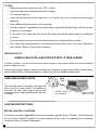
INSECT WARNING: Spiders and insects can nest in the burners of this and other outdoor ovens,
and cause the gas to flow from the front of the burner. This is a very dangerous condition, which can
cause a fire to occur behind the valve panel, thereby damaging the oven and making it unsafe to op-
erate. Inspect the oven at least twice a year.
Be sure all oven controls are turned off and the oven is cool before using any type of aerosol cleaner
on or around the oven. The chemical that produces the spraying action could, in the presence of
heat, ignite or cause metal parts to corrode.
Do not operate the oven under overhead combustible surfaces. Use only in well ventilated areas. Do
not use in buildings, garages, sheds, breezeways or any enclosed areas.
Keep the area surrounding the oven free from combustible materials, trash, or combustible fluids and
vapors such as gasoline or charcoal lighter fluids. Do not obstruct the flow of combustion gases and
ventilation airways.
Keep the back of the oven free and clear from debris.
If the unit is stored indoors ensure that it is cool. If propane is used, the cylinder must be unhooked
and the propane cylinder stored outside in a well-ventilated area, out of reach of children.
Never use the oven in windy conditions. If located in a consistently windy area, oceanfront, mountain-
top, etc... a windbreak will be required. Always adhere to the specified clearances.
Do not use the oven for cooking excessively fatty meats or products, which promote flare-ups.
! WARNING
FOR OUTDOOR USE ONLY
NOT TO BE INSTALLED IN OR
ON RECREATIONAL VEHICLES
AND / OR BOATS.
! WARNING
NEVER USE A DENTED OR
RUSTED LIQUID PROPANE
TANK. SHUT OFF TANK WHEN
NOT IN USE.
! AVERTISSEMENT
POUR UTILISATION À
L'EXTÉRIEUR
NE PAS ÊTRE INSTALLÉ DANS OU
SUR DES VÉHICULES RÉCRÉATIFS
ET / OU DES BATEAUX.
! AVERTISSEMENT
N'UTILISEZ JAMAIS DE RÉSERVOIR
DE PROPANE LIQUIDE BOSSELÉ
OU ROUILLÉ. ÉTEINDRE LE RESER-
VOIR LORSQU'IL N'EST PAS UTILI-
SÉ.

6
LOCATING AND ASSEMBLING THE PIZZA OVEN:
When determining a suitable location for your Artisan™ Pizza Oven, take into account concerns such
as exposure to wind, rain, sprinklers, proximity to traffic paths and keeping any gas supply line runs as
short as possible.
Locate the oven only in a well-ventilated area. Never locate the oven in a building, garage, breezeway,
shed or other such enclosed areas without an approved ventilation system. Never locate the oven over,
under or next to overhead combustible construction.
CLEARANCES:
TO NON-COMBUSTIBLE CONSTRUCTIONS:
A minimum of 3” clearance from the back of the oven Top Rear Exhaust to non-combustible
construction is required to allow the hot exhaust air to escape freely.
A minimum of 1” clearance around the oven perimeter (bottom section) to non-combustible construction
is required to allow air intake through the bottom of the unit for proper flame combustion.
TO COMBUSTIBLE CONSTRUCTIONS:
A minimum of 12” clearance from the back of the oven Top Rear Exhaust to combustible construction
is required to allow the hot exhaust air to escape freely.
A minimum of 1” clearance around the oven perimeter (bottom section) to combustible construction is
required to allow air intake through the bottom of the unit for proper combustion. Combustible materials
however, should never touch any exterior surface of the oven.
COUNTERTOPS:
It is recommended that the Artisan™ Pizza Oven be placed on top of non-combustible surfaces.
If the Artisan™ Pizza Oven is operated while on top of combustible countertops, discoloration or
damage could occur. Additionally countertops made of wood, laminates, wood composites and
countertops with other combustible materials like binders and / or finishes such as oil, lacquer, varnish,
shellac, paints or other combustible finishes are not recommended.
ASSEMBLY:
Before using your
Artisan™ Pizza Oven, complete the following steps:
1. Remove all packaging materials.
2. Ensure that the hearth (bottom) burner is positioned correctly on it’s orifice, and is fully
seated onto its supports (screwed in). It should not move.
3. Install the Hearth Stones and Top radiant.
4. Make the connection to the gas regulator according to the instructions on pages 10 & 11
for your gas type.
5. Allow a 1” (minimum, 6” preferably) clearance around all bottom sides of the oven for
proper air movement and avoid placing other items near it that might block airflow.

7
WARNING:
To prevent harm and ensure proper operation of your oven, the hearth (bottom) burner must be properly
installed with respect to the gas orifices. Be certain that the orifice is inserted completely into the
burner’s inlet and that the burner rests firmly on its support screw. It should not move.
The burner should not rock side-to-side nor top-to-bottom if properly installed. If excessive burner
movement is present, reseat the burner or contact your authorized service provider.
IMPORTANT ELECTRICAL / GAS INSTRUCTIONS:
USE ONLY A GROUND FAULT INTERRUPTER (GFI) PROTECTED CIRCUIT WITH THIS UNIT.
NEVER REMOVE THE GROUNDING PLUG OR USE WITH AN ADAPTER OF 2 PRONGS.
KEEP CORD AWAY FROM HEATED OVEN SURFACES.
DO NOT LET THE CORD HANG OVER THE EDGE OF A TABLE OR TOUCH HOT SURFACES.
DO NOT OPERATE ANY OUTDOOR GAS APPLIANCES WITH A DAMAGE CORD, PLUG, OR AFTER THE APPLIANCE MALFUNCTIONS
OR HAS BEEN DAMAGED IN ANY MANNER. CONTACT THE MANUFACTURER FOR REPAIR.
TO PROTECT AGAINST ELECTRIC SHOCK, DO NOT IMMERSE CORD OR PLUGS IN WATER OR OTHER LIQUIDS.
UNPLUG FROM THE OUTLET WHEN NOT IN USE AND BEFORE CLEANING.
INSPECT THE GAS HOSE BEFORE EACH USE. IF IT IS EVIDENT THAT THERE IS EXCESSIVE ABRASION OR WEAR, OR THE HOSE
IS CUT, IT MUST BE REPLACED PRIOR TO THE UNIT BEING OUT INTO OPERATION. A REPLACEMENT HOSE / REGULATOR WITH A
MINIMUM OF 60,000 BTUH CAPACITY SHOULD BE USED.
KEEP ANY ELECTRICAL SUPPLY CORD AND FUEL SUPPLY HOSE AWAY FROM ANY HEATED SURFACES.
ALLOW TO COOL BEFORE PUTTING ON OR TAKING OFF PARTS.
USE ONLY EXTENSION CORDS WITH A 3 PRONG GROUNDING PLUG, RATED FOR THE POWER OF THE EQUIPMENT, AND AP-
PROVED FOR OUTDOOR USE WITH A W-A MARKING.
! WARNING
INSTRUCTIONS IMPORTANTES D'ÉLECTRICITÉ / GAZ:
UTILISEZ UN CIRCUIT PROTÉGÉ PAR INTERRUPTEUR DE DÉFAILLANCE À TERRE (GFI) AVEC CETTE UNITÉ.
NE JAMAIS RETIRER LA FICHE DE TERRE OU UTILISER AVEC UN ADAPTATEUR DE 2 PRONGES.
GARDEZ LE CORDON DE LA SURFACES CHAUFFANTES.
NE LAISSEZ PAS LE CORDON PENDANT LE BORD D'UNE TABLE OU TOUCHEZ DES SURFACES CHAUDES.
NE FONCTIONNEZ PAS DES APPAREILS DE GAZ À L'EXTÉRIEUR AVEC UN CORDON DE DOMMAGE, UNE PLAQUE OU APRÈS LES
MALFUNCTIONS DE L'APPAREIL OU A ÉTÉ ENDOMMAGÉS DE QUELQUE MANIÈRE. CONTACTER LE FABRICANT POUR LA RÉPA-
RATION.
POUR PROTÉGER CONTRE LES CHOCS ÉLECTRIQUES, NE PAS IMMÉRIR LE CORDON OU LES PLAQUETTES DANS L'EAU OU
D'AUTRES LIQUIDES.
DÉBRANCHEZ-VOUS DE LA SORTIE QUAND IL N'EST PAS UTILISÉ ET AVANT DE NETTOYER.
INSPECTER LE TUYAU DE GAZ AVANT CHAQUE UTILISATION. SI IL EST EVIDENT QU'IL YA UNE ABRASION OU UN USAGE EXCES-
SIF, OU QUE LE TUYAU EST COUPÉ, IL DOIT ÊTRE REMPLACÉ AVANT QUE L'UNITÉ EFFECTUERA EN FONCTIONNEMENT. UN
TUYAU / RÉGULATEUR DE REMPLACEMENT AVEC UN MINIMUM DE 60 000 BTUH CAPACITÉ DEVRAIT ÊTRE UTILISÉ.
GARDEZ TOUT LE CORDON D'ALIMENTATION ÉLECTRIQUE ET LE TUYAU D'ALIMENTATION DE CARBURANT ÉLEVÉ DE TOUTES
SURFACES CHAUFFÉES.
PERMETT DE REFRIR AVANT DE METTRE EN PLACE OU DE DÉCHARGER DES PIÈCES.
N'UTILISEZ QUE DES CORDES D'EXTENSION AVEC UNE FICHE DE TERRASSEMENT DE 3 PRONGES, RATÉES POUR LA PUIS-
SANCE DE L'ÉQUIPEMENT, ET APPROUVÉES POUR UNE UTILISATION EXTÉRIEURE AVEC UN MARQUAGE W-A.
! AVERTISSEMENT

8
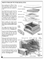
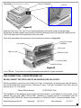
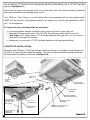
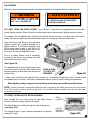
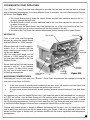
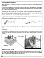
HEARTH STONE AND TOP STONE INSTALLATION:
After unpacking the Artisan™ Pizza
Oven and before using for the first
time, several items need to be proper-
ly installed for the oven to operate cor-
rectly.
The Hearth Stones as well as the Top
Stone must be located in the unit
along with the oven cavity top and ex-
haust assembly. These items are
shown on Figure # 1 and can be in-
serted through the oven top opening.
The stones have been wrapped prior
to shipment for their protection. It is
best to insert them by removing the
top cover of the oven on a countertop.
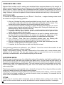
Before installing the Hearth stones,
verify that the stone’s support bar (at
the center) is properly located in the
oven’s cavity over the bottom (hearth)
burner.
The support bar simply locks-in into
the provided slots at both ends of the
bottom burner cavity. (See figure # 2)
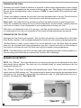
Once the Hearth Stones are installed
inside the oven, the Oven Cavity Top
can be inserted into the oven. The
cavity top rests between the side walls
and the oven cavity back wall.
(See figure # 2).
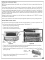
Please note that the Oven Cavity Top
front flange rests inside the front arch
of the oven main opening. Insert the
Oven Cavity Top at a slight angle
when restingthe top agains the sides
and back.
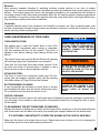
The Top Stone can now be placed so
it rests on top of the Oven Cavity Top.
Place the stone centered between the
notches of the oven cavity back wall.
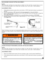
Insert the Exhaust Assembly by resting
it on top of the Oven Cavity Top and
locking it between the notches of the
back wall. (See Figure # 3).
TOP STONE
OVEN BODY
Figure # 1
EXHAUST ASSEMBLY
TOP COVER
HEARTH STONES
OVEN CAVITY TOP
HEARTH
SUPPORT
BAR
OVEN
DOOR
COVER
IGNITER
SUPPORT
BAR
HEARTH BURNER
SLOTS
Figure # 2
REAR
BURNER
IGNITER
IGNITER OVEN CAVITY TOP BACK WALL
FRONT ARCH

9
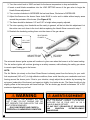
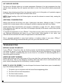
Install the Top Cover. The Top Cover should be placed from the back forward at a slight angle.
Simply align the back exhaust opening with the Exhaust Assembly back side and slide forward until all
Top Cover sides rest one the perimeter of the oven walls.
When fully assembled, all components would be placed as shown on Figure # 4:
Your Artisan™ Pizza Oven is now fully assembled and ready for its gas connection.
GAS CONNECTION—LIQUID PROPANE (LP)
NEVER CONNECT THE PIZZA OVEN TO AN UNREGULATED GAS SUPPLY.
Before proceeding, ensure the oven is fitted for LP gas. Connecting to an improper gas type will result in
poor performance and increased risk of damage or injury. Total gas consumption (per hour) with all
burners set on “HI” is a follows:
Hearth & Back Burners 37,000 BTUH Total
The installation of this appliance must conform with local codes or, in the absence of local codes, to the
national fuel gas code, ANSI Z223.1a-1988. Installation in Canada must be in accordance with the
Standard CAN/ CGA-B149.1 Natural Gas Installation or CAN/CGA-B149.2, Propane Installation Code.
Manifold pressure with LP Operating: 10.0” W.C. Non-operating: 11.2” W.C.
EXHAUST ASSEMBLY TOP STONE (SHOWN INSIDE EXHAUST ASSEMBLY)
NOTCH
Figure # 3
SUPPORT BAR
Figure # 4
HEARTH STONE
HEARTH STONE
TOP STONE
TOP COVER
FRONT COVER
EXHAUST PLENUM
ASSEMBLY

10
L.P. TANK REQUIREMENTS:
Use only a standard 20 Lbs. (5 Gal.) propane gas cylinder (approx. 12” Ø / 18” tall). The tank must be
installed in the upright position. Do not use a dented or rusty LP tank as it may be hazardous and
should be checked by your LP supplier. Never use a cylinder with a damaged valve.
The LP gas cylinder must be constructed and marked in accordance with the specifications for LP gas
cylinders of the U.S. Department of Transportation (DOT) 4BA, 4BW, and 4E.with an ACME thread/
OPD (over fill protection device) installed.
The cylinder must be provided with a shut off valve terminating in an LP gas supply cylinder valve outlet
specified, as applicable, for connection type QCC1 (CGA-791 or ACME threads) in the standard for
compressed gas cylinder valve outlet and inlet connections ANSI/CGA V-1.
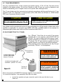
LP GAS CONNECTION TO LP TANKS:
Your Artisan™ Pizza Oven for use with LP gas comes
equipped with its own regulator, which MUST NOT be
removed. The oven is shipped with high capacity, hose /
regulator assembly for connection to a standard 20 Lb.
LP cylinder. The LP gas pressure regulator and hose
supplied with this oven must be used without alteration.
If this assembly needs to be replaced, use only the type
specified by Artisan™ for this appliance.
Pizza ovens require a 60,000 BTUH minimum regulator / hose assembly.
To connect the regulator / hose assembly follow the next steps:
Locate the regulator and gas connection point in the rear left side of your
Oven unit .
! WARNING
KEEP ANY ELECTRICAL CORD
AND FUEL SUPPLY HOSE AWAY
FROM ANY HEATED SURFACES.
! AVERTISSEMENT
GARDER TOUT LE CORDON ÉLEC-
TRIQUE ET LE TUYAU D'ALIMENTA-
TION DE CARBURANT À L'ÉGARD DE
TOUTES SURFACES CHAUFFANTES.
Figure # 5
CONNECTION POINT:
1/2” FPT X 3/8” FLARE
BRASS FITTING ON
TYPICAL LP
GAS TANK
LP REGULATOR AND HOSE
ASSEMBLY (PRESET TO 10” WC)
ELECTRICAL
CORD PLUG
! CAUTION
THE GAS PRESSURE REGULATOR PROVIDED
WITH THIS APPLIANCE MUST BE USED. RE-
PLACE WITH REGULATOR SES MODEL 220-0280
! MISE EN GARDE
LE RÉGULATEUR DE PRESSION DE GAZ FOURNI DE CE
APPAREIL DOIT ÊTRE UTILISÉ. REMPLACER AVEC LE RÉ-
GULATEUR SES MODÈLE 220-0280

11
Fasten the hose connection to the 1/2” FPT x 3/8” ODF (flare fitting) con-
nected to the elbow. (See Figure # 5). It is best to use a wrench of the ap-
propriate size to fasten this connection.
Fasten the hose regulator to the LP cylinder by hand tightening the green
connector to the tank valve until the knob stops rotating and it is fixed to the
cylinder’s valve.
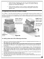
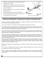
RECOMMENDED APPLIANCE AND CYLINDER PLACEMENT:
The Artisan™ Pizza Oven should be placed on a non-combustible countertop surface suitable for its
operation. (see page 6 for this information). The LP supply cylinder or tank should never be placed on
the counter next to the oven as radiated heat from the oven could possibly create a hazardous condition
and risk of explosion.
F
or safety, please note of the following instructions:
1. When an LP cylinder and hose is placed close to the unit, a tripping hazard with the hose or cyl-
inder might occur. (see Figure 6a and 6b)
2. The length of the hose and the location of the cylinder needs to be such as not to interfere with
the unit operation and if it was to fall to the ground, it will not strike the unit on its downward fall
nor pull the unit sufficiently to cause spillage of liquids or food, should the cylinder be tipped in
any direction.
3. It is recommended to use a standard 20 lbs. LP cylinder (approx. 12” Ø / 18” tall) designed for
vapor extraction marked in accordance of LP gas cylinders and US Department of Transportation
DOT specifications 4BA, 4BW, and 4E. (also approved under Transport Canada specifications
4BAM, 4BWM, and 4EM when necessary) with an ACME thread / OPD (overfill protection de-
vice) installed.
4. Connect and disconnect the hose according to the procedure on page 10 and always check for
gas leaks according to the procedure on page 16 & 17.
5. If the Pizza Oven is not in use, the gas must be turned off at the supply cylinder.
6. Storing the Pizza Oven indoors is permissible only if the cylinder is disconnected and removed
from the Pizza Oven.
Figure # 6a
Figure # 6b
Cylinder placed in
such way that cannot
strike the unit when
falling to the ground.
Cylinder and hose are
placed away from the
hot body of the oven.
DO NOT place the
cylinder in such a
way that it could
become a tripping
hazard or if tipped.
The cylinder could
drag the unit and
fall in the ground
while operating.
COUNTER
ACCESS DOOR
(optional)

12
7. Cylinders must be stored outdoors out of the reach of children and shall not be stored in a build-
ing, garage or any other enclosed area.
8. Only use the pressure regulator and hose supplied with your Pizza Oven. A replacement regula-
tor and hose assembly can be obtained by contacting Artisan™ Gourmet Grills.
9. The LP cylinder valve connection as well as the pressure regulator supplied should be attached
according to the diagram on page 10.
10. The LP cylinder should be placed upright for vapor withdrawal only. Never turn the cylinder side-
ways or upside down.
11. The LP cylinder must include a permanent collar to protect the cylinder valve at all times.
12. Do not store a spare gas cylinder under or near this Pizza Oven.
13. Never fill the LP cylinder beyond 80 % full.
14. If instructions 12 and 13 are not followed exactly, a fire causing death or serious injury may occur.
15. Place dust cap on cylinder valve outlet whenever the cylinder is not in use. Only install the type of
dust cap on the cylinder valve outlet that is provided with the cylinder valve. Other types of caps
or plugs may result in leakage of propane.
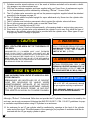
Although Artisan™ Professional Grills does not provide the LP cylinder, if one was to be used by the
end user, we strongly recommend following the ANSI Z21.89-2017 / CSA 1.18-2017 guidelines for prop-
er ventilation requirements when using LP cylinders in an enclosure:
16. An enclosure for an LP gas cylinder shall be ventilated by openings at the level of the cylinder
valve and at floor level. The effectiveness of the opening(s) for purposes of ventilation shall be de-
termined with the LP gas supply cylinder in place.
16.
! CAUTION
CYLINDERS MUST BE STORED OUTDOORS IN A
WELL VENTILATED AREA OUT OF THE REACH OF
CHILDREN.
DISCONNECTED LP CYLINDERS MUST HAVE THREADED
VALVE PLUGS TIGHTLY INSTALLED, AND MUST NOT BE
STORED IN A BUILDING, GARAGE OR ANY OTHER ENCLOSED
AREA. THE GAS MUST BE TURNED OFF AT THE SUPPLY CYL-
INDER WHEN THE UNIT IS NOT IN USE. IF THE APPLIANCE IS
STORED INDOORS, THE CYLINDER MUST BE DISCONNECTED
AND REMOVED FROM THE APPLIANCE.
! WARNING
YOUR ARTISAN™ PROFESSIONAL
GRILL’S PRESSURE REGULATOR HAS A
MAXIMUM INPUT PRESSURE OF 14” WC.
(OR APPROX. .5 PSI) , AND A SAFETY
LIMIT OF 69” WC. (2.5 PSI).
! REGULATOR NOTICE
Exposure to pressures above the safety
limit of 69” WC. will permanently damage
the gas regulator requiring a replacement.
OVER PRESSURE DAMAGE IS NOT COV-
ERED BY YOUR ARTISAN WARRANTY.
! MISE EN GARDE
LE CYLINDRE DOIT ÊTRE STOCKÉ À L'EXTÉRIEUR
DANS UN ENDROIT BIEN VENTILÉ ET HORS DE LA POR-
TÉE DES ENFANTS.
DÉBRANCHER LES BOUTEILLES DE LP DOIVENT
AVOIR DES BOUCHONS DE VALEUR VISSÉS
HERMÉTIQUEMENT INSTALLÉS, ET NE DOIVENT
PAS ÊTRE STOCKÉS DANS UN BÂTIMENT, GARAGE
OU TOUT AUTRE ESPACE FERMÉ. LE GAZ DOIT
ÊTRE ARRÊTÉ AU NIVEAU DU CYLINDRE D'ALIMEN-
! AVERTISSEMENT
VOTRE RÉGULATEUR DE PRESSION DE
ARTISAN PROFESSIONAL GRIL A UNE
PRESSION D'ENTRÉE MAXIMALE DE 14"
WC (OU ENVIRON 0,5 PSI), ET UNE LIM-
ITE DE SÉCURITÉ DE 69" WC (2,5 PSI).

13
17. This shall be accompanied by one of the following:
a. One side of the enclosure shall be completely open; or
b. For an enclosure having four sides, a top and a bottom (at least two) ventilation openings at
cylinder valve level shall be provided in the side wall, equally sized, spaced at 180 degrees
(3.14 rad), and unobstructed.
18. Each opening shall have a total free area of not less than ½ in
2
/lb. (7.1 cm
2
/kg) of stored fuel ca-
pacity and not less than a total free area of 10 in
2
(64.5 cm
2
). Example: 20 Lb. cylinder = 10 in
2
19. The ventilation opening(s) shall be provided at floor level and shall have a total free area of not
less than ½ in
2
/lb. (7.1 cm
2
/kg) of stored fuel capacity and not less than a total free area of 10 in
2
(64.5 cm
2
).
20. If ventilation openings at floor level are in a side wall, there shall be at least two openings. The bot-
tom of the openings shall be at floor level and the upper edge no more than 5 in (127 mm) above
the floor. The openings shall be equally sized, spaced at 180 degrees (3.14 rad) and unobstructed.
21. Every opening shall have minimum dimensions so as to permit the entrance of a 1/8 in (3.2 mm)
diameter rod.
LP GAS CONNECTION TO LP PIPED SYSTEMS:
An LP piped system is one with a large central LP tank that feeds the entire household. Those systems
are normally equipped with a high pressure regulator by the large LP tank and low pressure regulators
close to the home.
The gas line connectors must comply with the Standard for Connectors for Outdoor Gas Appliances
and Manufactured Homes, ANSI Z21.75 • CAS 6.27, and suitable for outside installation. The maximum
length of the connection shal be 6 Ft. (1.82 m)
GAS CONNECTION - NATURAL GAS (NG)
NEVER CONNECT THE PIZZA OVEN TO AN UNREGULATED GAS SUPPLY.
Before proceeding, ensure the oven is fitted for natural gas.
Connecting to an improper gas type will result in poor perfor-
mance and increased risk of damage or injury.
Total gas consumption (per hour) with all burners set on “HI” is
a follows:
Hearth & Rear Burner 38,000 BTUH Total
The installation of this appliance must conform with local codes
or, in the absence of local codes, to the national fuel gas code,
ANSI Z223.1a-1988. Installation in Canada must be in accord-
ance with the Standard CAN/ CGA-B149.1 Natural Gas Installa-
tion or CAN/CGA-B149.2, Propane Installation Code.
Manifold pressure with NG:
Operating: 5.0” W.C. (.14 PSI)
Non-operating: 5.5” W.C. (.16 PSI)
Optimum pressure: 7.0” W.C. (.25 PSI)
NOTE: To ensure proper heating performance of this appli-
ance, verify that the gas line supply pressure is adequate (7.0”
W.C. supply pressure is preferred) to maintain 5” W.C. manifold
pressure.
SHUT OFF HAND VALVE
MUST BE LOCATED IN
ACCESSIBLE AREA
INCOMING NG
GAS SUPPLY
1/2” Ø - NG
FLEXIBLE HOSE
Figure # 7

14
Use a minimum 1/2” Ø Flex Hose to prevent gas starvation. Alternatively, use a 1/2” NPT hard gas
pipeline. (See Figure # 7)
Ensure that the service pipe supplying the oven is fitted with a shut off valve conveniently positioned
and easily accessible as an emergency gas shutoff.
Your Artisan™ Pizza Oven for use with Natural Gas comes equipped with its own regulator which
MUST NOT be removed. If this regulator needs to be replaced use only the type specified by Arti-
san
™ for this appliance.
To connect the hose assembly follow the next steps:
Locate the regulator and gas connection point in the rear left side of your oven unit.
Fasten the Flex Hose connection to the 1/2” ODF (flare fitting) provided with the oven unit.
(See Figure # 7). When using a 1/2” Ø flexible stainless steel gas hose, do not connect a
hose that is more than 48” in length.
Alternatively, you can use a 1/2” NPT hard gas pipeline with the appropriate fittings.
COUNTERTOP INSTALLATIONS:
Because of the Artisan™ Pizza Oven’s unique countertop design, it is possible to install the gas sup-
ply (NG or LP) from a location below the counter. The oven is constructed with an opening at the bot-
tom heat shield to facilitate connections. (See figure # 8)
BOTTOM
HEAT
SHIELD
Figure # 8
3/8” OR 1/2”
COMPRESSION
CONNECTION
OPENINGS
REMOVE EXTERNAL
CABLE STRAIN RELIEF
GAS & ELECTRICAL
CONNECTION
DOWNWARDS
BOTTOM HEAT
SHIELD REMOVED
ELECTRICAL
CORD
FEED ELECTRICAL
PLUG THROUGH
BACK WALL AND
POINT DOWN.
NEW FLEXIBLE
GAS LINE
REMOVE 1/2” NPT X 3/8” ODF
ADAPTER (LP MODELS)
REMOVE 1/2” PIPE
EXTENSION
GAS PRESSURE
REGULATOR

15
Standard connections through the back panel can be converted to bottom connections as follows:
Removing the (4) 10-32 screws that support the bottom heat shield.
Removing the 1/2” gas line extension before the Gas Pressure Regulator and
adapter fitting (1/2” NPT x 3.8” ODF if present on LP Systems)
Removing the exterior electrical cable Strain Relief.
Feeding the electrical plug through the back panel downward.
Installing a new flexible gas line with appropriate fittings to the Gas Pressure Reg-
ulator and routing it downwards.
Re-installing the 10-32 screws to secure the bottom heat shield.
When considering installing the gas supply through the bottom of a non-combustible countertop, it is
recommended to have a 4” diameter hole located on the countertop for piping and electrical require-
ments.
The center of the 4” Ø hole should be located approximately 3” from the back panel and 3” from the right
side of the oven base. Keep in mind the final location, clearance to non-combustible materials and free
exhaust clearances required for the Pizza Oven when locating such access hole.
It is highly recommended that the 4” Ø hole be constructed in such manner as to provide a 3/8” raised
lip to prevent water or spills on the countertop from falling into the under-counter section. Refer to the
ARTP-PZA Specification sheet for additional information.
It is recommended to install an access door such as Artisan™ double sided doors, in order to reach
the LP Gas Tank or the NG Supply Gas Line shut-off valve as well as the GFCI receptacle to disconnect
power to the Pizza Oven.
Refer to Page 12 for ANSI Z21.89-2013 / CSA 1.18-2013 guidelines for proper ventilation requirements
when using LP cylinders in an enclosure.
LEAK TESTING:
GENERAL:
Although all gas connections on your
Artisan™ Pizza Oven are leak tested at the factory prior to ship-
ment, a complete gas tightness check must be performed at the installation site due to possible mishan-
dling in shipment, or excessive pressure unknowingly being applied to the unit.
Periodically check the whole system for leaks, or immediately check if the smell of gas is detected.
BEFORE TESTING:
Make sure that all packing material is removed from the oven.
Make sure the Burners are properly seated in the oven .
Do not smoke while leak testing.
Never leak test with an open flame.
Make a soap solution of one part liquid detergent and one part water for leak testing purposes.
Apply the solution to the gas fittings by using a spray bottle, or brush.
For LP units, always check with a full cylinder.

16
TO TEST:
Make sure all control valves are in the “OFF” position.
Apply the soap solution described above to all fittings.
Turn the gas supply on.
Check all connections from the supply line, or LP cylinder up to and including the manifold pipe
assembly.
Soap bubbles will appear where a leak is present.
If a leak is present, immediately turn off gas supply, tighten any leaking fittings, turn the gas sup-
ply back on, and recheck.
If you cannot stop a gas leak, turn off the gas supply and call the dealer where you purchased
your oven.
Do not use the Pizza oven until all connections have been checked and do not leak.
Only those parts recommended by the manufacturer should be used on the oven. Substitution
can void the Artisan™ Pizza Oven’s warranty.
IMPORTANT NOTE:
ALWAYS CHECK FOR LEAKS AFTER EVERY LP TANK CHANGE.
If a leak is present, or if the connection hose shows signs of wear, these conditions must be corrected
prior to using your oven.
Check all gas supply fittings for leaks before each use. It is handy to keep a spray bottle of soapy water
near the shut-off valve of the gas supply line. Spray all the fittings. Bubbles indicate leaks.
OVEN AND ACCENT LIGHTS:
The oven light button is located on the upper left
side of the front control panel. This switch con-
trols both the oven space light as well as the
front panel accent lights directly above the con-
trol knobs.
LIGHTING INSTRUCTIONS:
BEFORE LIGHTING LP SYSTEMS:
The pressure regulator (Type QCC1) and hose assembly supplied with the Artisan™ Pizza Oven must
be used. Never substitute regulators for those supplied with the oven. If a replacement is necessary,
contact the factory for proper replacement.
PUSH
FOR
LIGHT FIXTURE
(inside the oven)
ACCENT LIGHTS
(under bullnose)

17
NG SYSTEMS:
Make sure all connections are properly assembled whether is through the back or under the unit.
TO LIGHT, OPEN THE DOOR COVER. Your Artisan™ Pizza Oven is equipped with an automatic
burner lighting system. When the knob is pushed and turned, the automatic lighting system is active.
The system will immediately start a Spiral Hot Surface Igniter and open its safety gas valves when
ready. This system lights up the burners instantly as soon as gas has reached the burners.
Once the burner has been lit, the automatic
lighting system will continue glowing as a
safety measure. If the flame suddenly went
off by heavy wind or lack of fuel (NG or LP
gas) the automatic lighting system will contin-
ue to glow in order to relight the burner.
This is a safety feature that is constantly
monitoring the burner and making sure that
the flame is burning correctly.
(See Figure # 9)
The hearth burner is a very large burner locat-
ed at the bottom of the unit and heats up the
hearth stones by a direct flame as well as con-
vection heat.
It takes a few minutes for the hearth burner to warm up to operating temperature, thus if turned on and
immediately set to low heat, it will take a substantial amount of time to reach cooking temperatures.
When lighting, always keep your face and body as far away as possible from the burners.
NOTE: If electrical power is interrupted while the unit is operating, the safety gas valves will close within
10 to 30 seconds in order to avoid any gas leaks. The unit will resume operation once the electrical pow-
er has been restored.
TO VERIFY OPERATION OF BOTH BURNERS:
Look straight into the oven cavity for the Back Burner.
Flames should be directly visible at the back.
The Hearth Burner is visible through the front viewing port.
(see figure # 10).
The hearth burner is best viewed downwards at approxi-
mately 45° angle .
! WARNING
DO NOT ATTEMPT TO LIGHT THE
OVEN IF THE ODOR OF GAS IS PRE-
SENT. CALL FOR SERVICE.
! AVERTISSEMENT
N'ESSAYEZ PAS D'ALLUMER LE FOUR
SI L'ODEUR DU GAZ EST PRESENTE.
APPELER LE SERVICE.
PUSH & TURN
TO LIGHT UP
BURNERS
Figure # 9
HEARTH
BURNER
VIEWPORT
OPEN
DOORS
Figure # 10

18
PREHEATING THE OVEN:
Preheating the Hearth Stones at maximum is important to allow proper temperatures at lower settings
later on as well as speeding up the process of heating up the oven. After lighting the Hearth and Back
Burners and as described before, allow to preheat on “HIGH” for approximately 25 minutes before begin-
ning to cook.
If faster oven heating is desired, the over door cover may be placed back in the unit. This will allow the
oven to be heated in approximately 15 minutes only, when both burners are set to HIGH.
Please note: The Hearth Stones as well as the Top Stone are heavy and have a great thermal mass.
If they are overheated by leaving the unit on HIGH unattended for several minutes, (specially when the
oven cover is in place), it may be impossible to cook anything without burning your food.
While this is not detrimental to the unit in any way, it will take several minutes to cool off at low settings
or it might require to turn the oven completely off until normal cooking temperatures are restored.
PREHEATING THE TOP STONE:
Preheating the Top Stone is not necessary. The Top Stone sits directly in the exhaust flue of the Hearth
Stone Burner, therefore, it will be already preheated by the time the oven reaches cooking temperatures.
The Back Burner is used to create a blast of hot air and add heat to the Top Stone which will radiate
down onto the food and reach searing temperatures very fast. It should not be left on HIGH setting for
long times as it will make the oven Top Stone very hot beyond usable cooking temperatures.
NOTE: If the Back Burner is left ON to provide a warm and appealing glow while cooking, please do so
at a low setting with minimal flames to prevent the Top Stone from overheating.
BURNER ADJUSTMENTS:
NOTE: The Artisan™ Pizza Oven Burners do not require any primary air-mix adjustment as they have
been already factory adjusted. The need only to be checked visually for proper performance and low
temperature settings only.
The Artisan™ Pizza Oven is equipped with adjustable gas valves. These valves can be adjusted for
burner minimum (MIN) settings only. This procedure can be done by removing the gas adjustment knobs
and bezels on the front panel to expose the valve adjustment screw. (A small blade screw driver is re-
quired for this adjustment). (See Figure # 11)
KNOB REMOVED
FROM PANEL
Figure # 11
LOW SETTING
ADJUSTMENT SCREW

19
BACK BURNER LOW HEAT SETTING ADJUSTMENT:
NOTE:
THE LOW HEAT SETTING ON YOUR OVEN IS PRESET AT THE FACTORY. ADJUST ONLY IF ALTI-
TUDE OR ENVIRONMENTAL FACTORS ARE CAUSING POOR, LOW HEAT, PERFORMANCE.
ADJUSTMENT STEPS:
1. Follow lighting instructions and set the control knob on “HIGH” and allow the burner to preheat for 5
minutes.
2. Turn the control knob to “MIN” and wait for the burner temperature to drop and stabilize.
3. Insert a small flat blade screwdriver into the LOW SETTING screw of the gas valve to begin the
flame height adjustment.
4. Turn counter-clockwise to INCREASE the low heat BLUE flame, Clockwise to DECREASE.
5. Adjust the flames so the burner flame is approximately 1/8” to 3/16” in length in the LOW position.
(See Figure # 12)
Even if the flame is set very low, the automatic ignition system and its hot surface igniter will continue
glowing as a safety measure, while allowing the safety gas valves to remain open flowing gas to the
burner.
HEARTH STONE (BOTTOM BURNER) LOW HEAT SETTING ADJUSTMENT:
NOTE:
THE LOW HEAT SETTING ON YOUR OVEN IS PRESET AT THE FACTORY. ADJUST ONLY IF ALTI-
TUDE OR ENVIRONMENTAL FACTORS ARE CAUSING POOR, LOW HEAT, PERFORMANCE.
ADJUSTMENT STEPS:
1. Remove the Hearth stone closest to the oven opening in order to view the entire Hearth Burner.
2. Follow lighting instructions and set the control knob on “HIGH” and allow the burner to preheat for 5
minutes.
! WARNING
NEVER ADJUST THE BURNER SO LOW
THAT IT MAY GO OUT DURING USE. DO
NOT OPERATE THE OVEN WITH THE LOW
HEAT SCREW REMOVED.
GAS CAN ESCAPE AND CAUSE A
POTENTIALLY HAZARDOUS CONDITION.
! AVERTISSEMENT
NE JAMAIS AJUSTER LE BRÛLEUR SI BAS QU'IL
PEUT S'ÉTEINDRE PENDANT L'UTILISATION.
N'UTILISEZ PAS LE FOUR AVEC LA VIS À
CHALEUR BASSE RETIRÉE.
LE GAZ PEUT S'ÉCHAPPER ET PROVOQUER
UNE CONDITION POTENTIELLEMENT
DANGEREUSE.
FLAME SIZE
1/8” ~ 3/16”
MAXIMUM
Figure # 12
BACK BURNER LOW
FLAME SETTING
NON-ADJUSTABLE
AIR MIX

20
3. Turn the control knob to “MIN” and wait for the burner temperature to drop and stabilize.
4. Insert a small blade screwdriver into the LOW SETTING screw of the gas valve to begin the
Hearth Burner adjustment.
5. Turn counter-clockwise to INCREASE the low heat flame, Clockwise to DECREASE.
6. Adjust the flames so the burner flame looks BLUE in color and is stable without empty areas
around the perimeter of the burner (See Figure # 13)
7. The flame should be between 1/8” and 3/16” in height when properly adjusted.
8. The door opening, door threshold and the cavity in general, will be hot after this adjustment. Let
the entire oven cool down to the touch before replacing the Hearth Stone removed in step 1.
9. Reattach the knobs by pushing them onto the stems of the gas valves.
The automatic burner igniter system will continue to glow even when the burner is at it’s lowest setting.
The hot surface igniter will continue glowing as a safety measure, while allowing the safety gas valves
to remain open flowing gas to the burner.
NOTE:
The Air Shutter (air mixer) on the Heart Stone Burner is already preset from the factory for your units’
fuel requirement (NG or LP). In high altitude conditions, there could there be poor combustion and soot
forming around the burner ports. If that is your situation, simply adjust the air-shutter by loosening the
set screw (underside of the burner) and open just slightly for a better air-mix. The flame should only be
slightly yellow at the base ports and have blue tips. The air shutter gap should be between 1/8” to 3/8”
maximum depending on your fuel.
! WARNING
NEVER ADJUST THE BURNER SO LOW
THAT IT MAY GO OUT DURING USE. DO
NOT OPERATE THE OVEN WITH THE LOW
HEAT SCREW REMOVED.
GAS CAN ESCAPE AND CAUSE A
POTENTIALLY HAZARDOUS CONDITION.
! AVERTISSEMENT
NE JAMAIS AJUSTER LE BRÛLEUR SI BAS QU'IL
PEUT S'ÉTEINDRE PENDANT L'UTILISATION.
N'UTILISEZ PAS LE FOUR AVEC LA VIS À
CHALEUR BASSE RETIRÉE.
LE GAZ PEUT S'ÉCHAPPER ET PROVOQUER
UNE CONDITION POTENTIELLEMENT
DANGEREUSE.
AIR MIXER
OPENING
BLUE COLOR
FLAMES
Figure # 13
SET SCREW
(UNDERSIDE)
AIR SHUTTER GAP
APPROX. 1/4” GAP
FLAME SIZE
1/8” ~ 3/16”
MAXIMUM
La page est en cours de chargement...
La page est en cours de chargement...
La page est en cours de chargement...
La page est en cours de chargement...
La page est en cours de chargement...
La page est en cours de chargement...
La page est en cours de chargement...
La page est en cours de chargement...
La page est en cours de chargement...
La page est en cours de chargement...
La page est en cours de chargement...
La page est en cours de chargement...
-
 1
1
-
 2
2
-
 3
3
-
 4
4
-
 5
5
-
 6
6
-
 7
7
-
 8
8
-
 9
9
-
 10
10
-
 11
11
-
 12
12
-
 13
13
-
 14
14
-
 15
15
-
 16
16
-
 17
17
-
 18
18
-
 19
19
-
 20
20
-
 21
21
-
 22
22
-
 23
23
-
 24
24
-
 25
25
-
 26
26
-
 27
27
-
 28
28
-
 29
29
-
 30
30
-
 31
31
-
 32
32


Alfresco ARTP-PZA Artisan Pizza Oven Manuel utilisateur
- Taper
- Manuel utilisateur
- Ce manuel convient également à
dans d''autres langues
Documents connexes
Autres documents
-
 RST Brands OP-PSCLB5MFT-GY-K Mode d'emploi
-
 Vida by PADERNO Portable Outdoor Pizza Oven Le manuel du propriétaire
-
Camp Chef PZOVEN Mode d'emploi
-
Breckwell BH3024 Manuel utilisateur
-
R.H. Peterson American Fyre Designs Unvented Series Installation & Owner's Manual
-
Everdure EKILN1SUS Manuel utilisateur
-
Twin Eagles Salamangrill TESG-24N Manuel utilisateur
-
Omcan CE-CN-0748 Manuel utilisateur
-
LaToscana BRIONI LAVELLO Mode d'emploi
-
Blackstone 1575 Le manuel du propriétaire

