LG LP-E5082ZL.NW8SAF Guide d'installation
- Catégorie
- Climatiseurs split-system
- Taper
- Guide d'installation

P/No. : 3828A30075G
ENGLISH
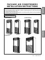
PACKAGE AIR CONDITIONERS
INSTALLATION INSTRUCTIONS
• Please read this instruction sheet completely before installing the product.
• When the power cable is wanted to replace, replacement work shall be performed
by authorized personnel only.
• Installation work must be performed in accordance with national wiring standards
by authorized personnel only.
Applied Model:
(1) 28K/30K(Btu/h)
(2) 44K/50K(Btu/h)
(3) 80K(Btu/h)
FRANÇAIS

2
Contents
1. The following should always be observed for safety
......................................
3
2. Installation of Indoor, Outdoor Unit
..................................................................
4
1) Selection of the best location
2) Indoor unit installation
3) Outdoor unit installation
4) Refrigerant amount
3. Installation Method
.............................................................................................
7
1) Procedure
2) Preparation of installation parts and tools
4. Piping of Indoor Unit
..........................................................................................
9
1) Preparation of piping
2) Connection of piping
3) Precautions in bending
5. Connecting the Cable to Indoor Unit
................................................................
11
6. Connecting piping and the Cable to Outdoor Unit
..........................................
12
1) Connecting the piping to the outdoor unit
2) Connecting the cable to the outdoor unit
7. Power Supply and Wiring
...................................................................................
13
1) Power spply
2) Wiring
8. Air Purging of the Piping and Indoor Unit
........................................................
14
9. Checking the Drainage and Form the Piping
...................................................
16
1) Checking the Drainage
2) Form the Piping
10. Final Check and Test Run
................................................................................
18

3
ENGLISH
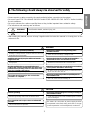
1. The following should always be observed for safety
• Please report to or take consent by the supply authority before connection to the system.
• Be sure to read "THE FOLLOWING SHOULD ALWAYS BE OBSERVED FOR SAFETY" before installing
the air conditioner.
• Be sure to observe the cautions specified here as they include important items related to safety.
• The indications and meanings are as follows.
• After reading this manual, be sure to keep it together with the instruction manual in a handy place on the
customer's site.
Could lead to death, serious injury, etc.
Do not install it yourself (customer).
Perform the installation securely referring to the
installation manual.
Install the unit securely in a place which can bear the
weight of the unit.
Perform electrical work according to the installation
manual and be sure to use an exclusive circuit.
Attach the electrical part cover to the indoor unit and the
service panel to the outdoor unit securely.
Be sure to use the part provided or specified parts for
the installation work.
Check that the refrigerant gas due not leak after
installation is completed.
Perform grounding
Do not install the unit in a place where an inflammable
gas leaks.
Perform the drainage/piping work securely according to
the installation manual.
Use the specified wires to connect the indoor and
outdoor units securely and attach the wires firmly to the
terminal board connecting sections so the stress of the
wires is not applied to the sections.
• Incomplete installation could cause injury due to fire, electric shock, the
unit falling or a leakage of water. Consult the dealer from whom you
purchased the unit or special installer.
• Incomplete installation could cause a personal injury due to fire,
electric shock, the unit falling or a leakage of water.
• When installed in an insufficient strong place, the unit could fall
causing injured.
• Incomplete connecting and fixing could cause fire.
• If the capacity of the power circuit is insufficient or there is incomplete
electrical work, it could result in a fire or an electric shock.
• The use of defective parts could cause an injury or leakage of water
due to a fire, electric shock, the unit falling, etc.
• If gas leaks and accumulates in the area surrounding the
unit, it could cause an explosion.
• If there is a defect in the drainage/piping work, water
could drop from the unit and household goods could be
wet and damaged.
The means for connection to power supply shall be
incorporated in the fixed wiring and have an air gap
contact separation in all active(phase) conductors.
• This product should be grounded.
• Defective grounding could cause an electric shock.
• If the electrical part cover if the indoor unit and/or the service panel if
the outdoor unit are not attached securely, it could result in a fire or
electric shock due to dust, water, etc.
Could lead to serious injury in particular environments when operated incorrectly.
WARNING
WARNING
CAUTION
CAUTION

4
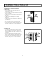
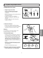
2. Installation of Indoor, Outdoor unit
5cm
40cm
5cm
100cm
50cm
50cm
50cm
100cm
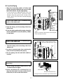
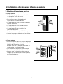
1) Selection of the best location
¤ Indoor unit
¤ŁOutdoor unit
• There should not be any heat source or
steam near the unit.
• There should not be any obstacles to prevent
the air circulation.
• A place where air circulation in the room will
be good.
• A place where drainage can be easily
obtained.
• A place where noise prevention is taken into
consideration.
• Do not install the unit near the door way.
• Ensure the spaces indicated by arrows from
the wall, ceiling, fence, or other obstacles.
• If an awning is built over the unit to prevent
direct sunlight or rain exposure, be careful
that heat radiation from the condenser is not
restricted.
• There should not be any animals or plants
which could be affected by discharged hot air.
• Ensure the space indicated by arrows from
the wall, ceiling, fence, or other obstacles.

5
ENGLISH
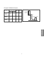
5/8" 3/8" 25 20
3/4" 3/8" 30 25
1" 5/8" 40 25
¤ØPiping length and the elevation
28K/30K
(BTU/h)
44K/50K
(BTU/h)
80K
(BTU/h)
PIPE SIZE
MODEL
GAS SIDE LIQUID SIDE
Max.
Length
A (m)
Max.
Elevation
B (m)
A
B
Indoor unit
Outdoor unit

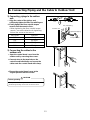
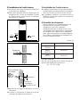
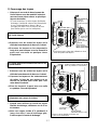
2) Indoor Unit installation
¤
The mounting floor should be strong and
solid enough to prevent it from vibration.
¤Ł
Drill the piping hole with 70mm diameter
hole-core drill at either the right or the left of
indoor unit. The hole should be sightly slant
to the outdoor side.
¤Ø
Insert the plastic tube through the hole.
¤Œ Cut the extruded outside part of the plastic
tube, if necessary.
3) Outdoor unit Installation
¤
Install the outdoor unit on the concrete or any
solid base securely and horizontally by
securing it with bolts (Ø12mm) and nuts.
¤Ł
If there is any vibration transmitted to the
building, mount the rubber underneath the
outdoor unit.
4) Refrigerant amount
Before shipment, this air conditioner is filled
with the rated amount of refrigerant including
additional amount required for air-purging,
subject to 5m piping length. (The rated
amount of refrigerant is indicated on the
name plate.) But when the piping length
exceeds 5 meters, additional charge is
required according to the following table.
(Unit: g)
Example) 28K/30K
In case of 10m long pipe(one-way), the amount
of refrigerant to be replenished is:
(10 - 5) x 30 = 150g
200mm
70mm
70mm
90mm
Wall
Core Drill
Tilt
Cut if necessary
More than 15mm
Wall
Plastic tube
(Bushing)
INSIDE OUTSIDE
MODEL
28K/30K
(BTU/h)
44K/50
(BUT/h)
80K
(BUT/h)
REFRIGERANT CHARGE
30 per 1m
40 per 1m
50 per 1m
6

7
ENGLISH
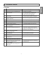
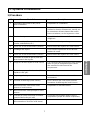
3. Installation Method
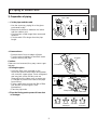
No. Installation works Descriptions
1 Preparation of tools and installation parts Preparation of installation
2 Flaring the pipes To insert the flare nuts, mounted on the
connection parts of both indoor and
outdoor unit, onto the copper pipes.
3 Pipe bending To reduce the flow resistance of refrigerant.
4 Connection of installation parts Connection of long piping
(elbows, socket etc)
5 Tighten the flare nut (outdoor) Connecting the pipings of the outdoor unit.
6 Blowing the pipings To remove dust and scale in working.
7 Tighten the flare nut (indoor) Connecting the pipings of the indoor unit.
8 Check a gas-leakage of the connecting
part of the pipings.
9 Air purging of the piping and indoor unit The air which contains moisture and which
remains in the refrigeration cycle may cause a
malfunction on the compressor
10 Open the 3-way (liquid side) and
3-way (gas side) valves.
11 Form the pipings To prevent heat loss and sweat
12 Checking the drainage (indoor unit) To ensure if water flow drain hose of indoor unit.
13 Connecting the cable between outdoor Preparation of the operating
and indoor unit
14 Connecting the main cable to outdoor unit
15 Supply the power to the crankcase heater To prevent the liquid back to the compressor.
(Before the operating the unit) (Heat pump only)
16 Cooling operation
(Use the remote control or display of the
indoor unit)
1) Procedure

8
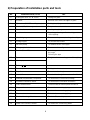
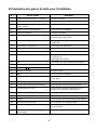
2) Preparation of installation parts and tools
No. Installation Parts, Tools Use
1 Flaring tool (Ø 6,35 - Ø 19,05) Flaring the pipes
2 Remear Remove burrs from cut edges of pipes.
3 Pipe cutter (MAX 35mm Copper pipe) Cutting the pipings
4 Wrench (H5, H4 hexagonal wrench) To open the service valve
5 Pipe bender Bending the pipings
6 Leak detector Check a gas-leakage of connecting part
of the pipings
7 Manifold gauge
To measure the pressure, to charge the refrigerant
8 Charge-nipple To connect the bombe
9 Vacuum pump To remove the air in the pipe.
10 Charge cylinder balance To measure the refrigerant amount
11 Bombe (Freon-22) Gas charge
Air purge
Cleaning the pipe
12 Spanner To tighten the connecting parts of the pipings
13 Monkey spanner
14 Driver( , )
15 Benchi (150mm) Cutting the wires
16 Tapeline To measure the length
17 Core drill
To make holes through the concrete wall and blocks
18 Voltmeter, Amperemeter, Clampmeter To measure the current and voltage
19 Insulation resistance tester To measure the insulation resistance
20 Glass thermometer
To measure the intake and outlet air temperature of the indoor unit
21 Copper tubes To use the connecting pipings
22 Insulation material To cover the connecting pipings
23 Tape To finish the connecting pipings
24 Electrical Leakage Breaker To shut off the main power
25 Cable
To connect the cable from outdoor unit to indoor unit
26 Drain hose sockets, elbows To remote the condensing water

ENGLISH
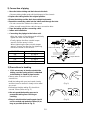
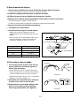
1) Preparation of piping
¤ Cut the pipes and the cable
• Use the accessory piping kit or the pipes
purchased locally.
• Measure the distance between the indoor
and the outdoor unit.
• Cut the pipes a little longer than measured
distance.
• Cut the cable 1.5m longer than the pipe
length.
¤ŁRemove burrs.
• Remove burrs from cut edges of pipes.
• Turn the pipe end down to avoid the metal
powder entering the pipe.
Caution:
If burrs are not removed, they may cause a gas
leakage.
¤ØFlaring the pipes.
• Insert the flare nuts, mounted on the
connection ports of both indoor and outdoor
unit, onto the copper pipes. Some refrigerant
gas may leak, when the flare nuts are
removed from the indoor unit, as some gas
is charged to prevent the inside of the pipe
from rusting.
• Fit the copper pipe end into the Bar of flare
tool about 0~0.5mm higher. (See
illustaration)
• Flare the pipe ends.
¤ŒTape the flaring part to protect it from dust
or damages.
90°
Pipe cutter
Slanted Rough
Pipe
Point down
Reamer
Bar
0~0.5mm
Copper
pipe
Clamp handle
Bar
Handle
Yoke
Cone
Red arrow mark
4321
= Improper flaring =
Inclined Cracked Surface
damaged
Uneven
thickness
4. Piping of Indoor Unit
9

• Align the center of the pipings and suffciently
tighten the flare nut with fingers.
• Finally, tighten the flare nut with troque
wrench until the wrench clicks.
When tightening the flare nut with troque
wrench, ensure the direction for tightening
follows the arrow on the wrench.
3) Precautions in bending
¤
If it is necessary to bend or stretch the
tubing, use the spring which is attached
to the tubing in stead of pipe bender.
• Please make a careful notice to make a
smooth line.
• Hold the tubing with your two hands closely
and then bend or stretch it slowly not to make
any crack.
• Remember that the radius (R) should not
exceed 70mm (Refer to Fig. 1)
¤ŁDo not repeat the bending process to
prevent the tubing from cracking or
crushing.
¤ØKeep in mind that the bending part should
not be cracked and make the radius (R) as
long as possible (Refer to Fig. 2)
PIPE SIZE TORQUE
3/8" 4.2 Kg
.
m
1/2" 5.5 Kg
.
m
5/8" 5.5 Kg
.
m
3/4" 6.5 Kg
.
m
Indoor unit tubing
Flare nut
Pipings
Torque wrench
Spanner
Spring
R70mm
(Fig. 1)
(Fig. 2)
R
2) Connection of piping
¤ Move the indoor tubing and drain hose to the hole
• Remove tubing holder and pull the tubing out of the chassis.
¤ŁReplace the tubing holder into original position
¤ØRoute the tubing and the drain hose staight backwards.
¤ŒInsert the connecting cable into the indoor unit through the hole.
• Do not connect the cable to the indoor unit
• Make a small loop with the cable for easy connection later.
¤ºTape the tubing and the connecting cable.
¤ Indoor unit installation.
¤ Connecting the pipings to the indoor unit.
10

11
ENGLISH
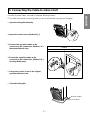
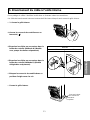
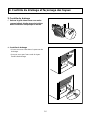
5. Connecting the Cable to Indoor Unit
• In order to protect cable, it should be inserted “Bushing Rubber”.
• The inside and outside connecting cable can be connected after opening the inlet grille.
Method
"A"
"B"
¤ Open the inlet grille manually.
¤ŁOpen the control cover with Driver(§]).
¤ØConnect the supplied cables to the
connector in the control box. (Method "A")
(Heat pump Model only)
¤ŒConnet the supplied cables to the
connector in the control box. (Method "B")
(Cooling Model only)
¤ºSecure the control cover to the original
position with the screw.
¤ Close the inlet grille.
Knock-out holes
Bushing rubber

¤Ø
Secure the control board cover to the
original position with the screws.
1) Connecting pipings to the outdoor
unit .
¤
Align the center of the pipings and
sufficiently tighten the flare nut with fingers.
¤Ł
Finally tighten the flare nut with torque
wrench until the wrench clicks.
• When tightening the flare nut with torque
wrench, ensure the direction for tightening
follows the arrow on the wrench.
2) Connecting the cables to the
outdoor unit
12
6. Connecting Piping and the Cable to Outdoor Unit
¤
Open the control board cover from the
outdoor unit by removing the screws.
Gas side piping
Liquid side piping
Torque wrench
Outdoor unit
¤Ł
Connect wires to the terminals on the
control board individually and secure the
cables onto the control board with clamp.
PIPE SIZE TORQUE
3/8" 4.2 Kg
.
m
1/2" 5.5 Kg
.
m
5/8" 5.5 Kg
.
m
3/4" 6.5 Kg
.
m
Perform grounding
• This product should be grounded.
• Defective grounding could cause an electric shock.
CAUTION

13
ENGLISH
H/P
450/750V 4.0mm
2
13.3mm
C/O
450/750V 2.5mm
2
11.8mm
H/P
450/750V 4.0mm
2
17.0mm
C/O
450/750V 4.0mm
2
17.0mm
H/P
450/750V 5.5mm
2
17.0mm
C/O
450/750V 5.5mm
2
17.0mm
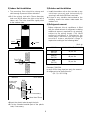
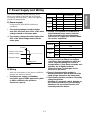
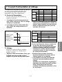
UNIT Circuit breaker capacity
Voltage
Time
Starting point
Power source voltage
working voltage
Starting voltage
The unit is completely wired internally at the
factory according to general rule of electrical
technology, but local rules, if they are required,
should be complied with.
1) Power supply
Power source must fulfill the following
conditions:
¤ The working voltage should be higher
than 90% and lower than 110% of the rated
voltage marked on the name plate.
¤Ł The starting voltage should be higher than
85% of the rated voltage marked on the
name plate.
¤Ł Provide a recognized circuit breaker as
below between power source and unit.
A disconnection device to adequately
disconnect all supply lines must be fitted.
(for service operations)
¤Ø The screws which fasten the wiring in the
casing of electrical fittings are liable to
come loose from vibrations to which the
unit is subjected during the course of
transportation. Check them and make sure
that they are all tightly fastened.
(If they are loose, it could give rise to
burn-out of the wires.)
¤ŒSee to it that the starting voltage is
maintained at more than 90 percent of the
rated voltage marked on the name plate.
¤ºThe following troubles would be caused by
voltage drop-down.
Vibration of a magnetic switch, damage on
the contact point there of, fuse breaking,
disturbance to the normal function of a
overload protection device.
2) Wiring
After the confirmation of the above conditions,
prepare the wiring as follows:
¤ Use the power supply cord(Rubber
insulation, type Ho7RNF approved by HAR
or SAA) suitable for the product's
electriccal capacity.
7. Power Supply and Wiring
UNIT VOLTS
Conductor
cross-sectional
area
Outside
diameter
H/P 30A
C/O 30A
H/P 40A
C/O 40A
H/P 50A
C/O 50A
28K/30K
44K/50K
80K
28K/30K
44K/50K
80K

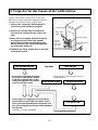
Outdoor unit
To indoor unit
Hexagonal wrench
Service port cap
3-way valve cap
(gas side)
3-way valve cap
(liquid side)
No leakage found leakage found
leakage ceased
leakage ceased
leakage persists
8. Air Purging of the Piping and Indoor Unit
The air which contains moisture and which
remains in the Refrigeration cycle may cause a
malfunction on the compressor.
¤ Remove the caps from the 3-way(liquid side)
and 3-way(gas side) valves.
¤Ł Remove the service-port cap from the 3-way
(gas side) valve.
¤ØTo open the valve, turn the valve stem of
3-way (liquid side) valve counter-clockwise
approx. 90° and hold it there for ten seconds,
then close it.
¤ŒCheck a gas-leakage of the connecting
portion of the pipings.
¤ºTo open 3-way(liquid side) valve
again, turn the valve stem
counter-clockwise until it stops.
¤ To purge the air, push the pin on the service port
of 3-way(gas side) valve for three seconds using
with a hexagonal wrench and set it free for one
minute.
• Repeat this three times.
Result
• Re-tighten the connecting portion with
torque wrenches.
14

15
ENGLISH
¤
Set the both 3-way(liquid side) and 3-way(gas side) valves to open position with the
Hexagonal wrench for the unit operation.
¤
Checking a gas leakage for the left piping.
• Connect the manifold gauge to the service port of 3-way(gas side) valve.
Measure the pressure.
• Keep it for 5 - 10 minutes.
Ensure if the pressure indicated on the gauge is as same as that of measured at first time.
CLOSE CLOSE
Closed
Closed
Indoor unit
Outdoor unit
Liquid side
Gas side

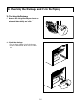
9. Checking the Drainage and Form the Piping
1) Checking the Drainage
¤ Remove the inlet grille with your hands as
shown (right and left) and pull in the
direction indicated by the arrow.
¤Ł Check the drainage
• Pour a glass of water into the drain pan.
• Ensure if water flows drain hose of indoor
unit.
16

17
ENGLISH
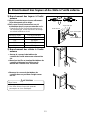
2) Form the Piping
¤ Wrap the connecting portion of indoor unit
with the insulation material and secure it with
two Plastic Bands. (for the right piping)
• If you connect an additional drain hose, the
end of the drain-outlet should be kept
distance from the ground. (Do not dip it into
water, and fix it on the wall to avoid swinging
in the wind.)
¤ŁTape the Piping, and Connecting Cable from
down to up.
¤ØForm the piping gathered by taping along the
exterior wall and fix it onto the wall by saddle
or equivalent.
¤ Tape the piping and connecting cable from
down to up.
¤ŁIn order to prevent water from entering the
room, form a trap and tape the piping.
¤Ø Fix the piping onto the wall with saddle or
bracket.
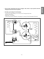
¤ When using the drain elbow hose, use
a mount of 3cm of higher.
¤ŁIn the cold district (0°c continued for 2~3
day), the drain water is frozen and the fan fail
to function, do not use the drain elbow.
In case of the outdoor unit is installed below
position of the indoor unit.
In case of the outdoor unit is installed upper
position of the indoor unit.
Drain water treatment of outdoor unit(Heat
Pump Only)
Trap
Drain elbow
Hose(inner diameter ø20)
Arrange the hose downward slope without waving.
Trap
Seal a small opening around
the piping with gum type sealer.
Gas side
piping
Main cable
Tube PE
Foam
Connecting
Cable
(For heater)
Connecting
Cable
Trap is required to prevent the electrical parts
from entering the water.

10. Final Check and Test Run
After installing the unit, perform the final check
and running test as follows:
Final check points
¤ Is the unit securely mounted?
¤ŁIs the installation location adequate?
¤ØIs the water piping work adequately and
without leakage?
¤ŒAre trapped drain lines installed at
condensate drain connections?
¤ºHas the refrigeration cooling cycle been
kept sealed?
¤ Is the electrical wiring adequate and are
the screws tightened on terminals?
After the above final checkings, prepare the
running test as follows:
¤ Connect compound gauges to the check
joints at discharge and suction sides of
the compressor.
¤ŁTurn all switches "OFF".
¤ØTurn the main switch "ON".
Running test should be accomplished as follows:
¤ Set operation switch at "FAN" and the fan
will start. Check to ensure that the fan
sounds normal.
¤ŁNext, set it at "COOL" and the compressor
will start. Check to ensure that the
compressor sounds normal.
¤ØCheck discharge and suction pressure on
the compound gauges.
¤ŒCheck working voltage, phase balance and
running current.
¤ºCheck to ensure that the thermistor
functions properly.
¤ Check to ensure that the high pressure
control switch functions correctly.
18
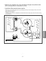
ONOFF
ON
FUSE(250V 3A)
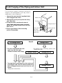
Heater Switch
Main PCB
Duct Switch
OFF
(
MICOM
)
Duct
Blower
Intake Air
Outlet Air
Barrier
Blower
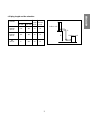
The Method of Duct Installation (Only 80K Model)
CORRECT INSTALLATION
1. Turn ON Duct switch of Main PCB.
2. After removing upper side chamber, connect the
duct to the Barrier Blower directly.

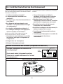
FRANÇAIS
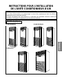
INSTRUCTIONS POUR L’INSTALLATION
DE L’UNITÉ CONDITIONNEUR D’AIR
• Lisez s’il vous plaît complètement ces instructions avant de commence l’installation du produit.
• Si le câble d’alimentation est endommagé, le travail de remplacement doit Ítre effectué
uniquement par un personnel autorisé.
• Le travail d’installation doit être effectué en conformité aux standards nationaux relatifs aux
installations électriques et uniquement par du personnel autorisé.
Modèle Appliqué:
(1) 28K/30K(Btu/h)
(2) 44K/50K(Btu/h)
(3) 80K(Btu/h)

2
Contenu
1. Les indications suivantes doivent toujours être suivies pour votre sécurité
...
3
2. Installation des unités interne et externe
..............................................................
4
1) Sélection du meilleur emplacement
2) Installation de l’unité interne
3) Installation de l’unité externe
4) Quantité de réfrigérant
3. Système d’installation
............................................................................................
7
1) Procédure
2) Préparation des pièces et instruments pour l’installation
4. Tuyaux de l’unité interne
........................................................................................
9
1) Préparation des tuyaux
2) Branchement des tuyaux
3) Précautions
5. Branchement du câble à l’unité interne
..............................................................
11
6. Branchement des tuyaux et du câble à l’unité externe
......................................
12
1) Branchement des tuyaux à l’unité externe
2) Branchement des câbles à l’unité externe
7. Courant d’alimentation et câblage
.......................................................................
13
1) Courant d’alimentation
2) Câblage
8. Purge de l’air des tuyaux et de l’unité interne
....................................................
14
9. Contrôle du drainage et façonnage des tuyaux
.................................................
16
1) Contrôle du drainage
2) Façonnage des tuyaux
10. Contrôle final et test de fonctionnement
...........................................................
18
La page est en cours de chargement...
La page est en cours de chargement...
La page est en cours de chargement...
La page est en cours de chargement...
La page est en cours de chargement...
La page est en cours de chargement...
La page est en cours de chargement...
La page est en cours de chargement...
La page est en cours de chargement...
La page est en cours de chargement...
La page est en cours de chargement...
La page est en cours de chargement...
La page est en cours de chargement...
La page est en cours de chargement...
La page est en cours de chargement...
La page est en cours de chargement...
-
 1
1
-
 2
2
-
 3
3
-
 4
4
-
 5
5
-
 6
6
-
 7
7
-
 8
8
-
 9
9
-
 10
10
-
 11
11
-
 12
12
-
 13
13
-
 14
14
-
 15
15
-
 16
16
-
 17
17
-
 18
18
-
 19
19
-
 20
20
-
 21
21
-
 22
22
-
 23
23
-
 24
24
-
 25
25
-
 26
26
-
 27
27
-
 28
28
-
 29
29
-
 30
30
-
 31
31
-
 32
32
-
 33
33
-
 34
34
-
 35
35
-
 36
36


LG LP-E5082ZL.NW8SAF Guide d'installation
- Catégorie
- Climatiseurs split-system
- Taper
- Guide d'installation