Miller Coolmate 4 Le manuel du propriétaire

Catégorie
Système de soudage
Taper
Le manuel du propriétaire

Ce manuel convient également à

OWNER’S MANUAL
OM-624 126 174S
200907
CE And Non-CE Models
Coolmate 4
1. Safety Symbol Definitions
DANGER! Indicates a hazardous situation which, if not
avoided, will result in death or serious injury. The possible
hazards are shown in the adjoining symbols or explained
in the text.
DANGER! Indique une situation dangereuse qui si on
l’évite pas peut donner la mort ou des blessures graves. Les
dangers possibles sont montrés par les symboles joints ou
sont expliqués dans le texte.
Have only trained and qualified persons install, operate,
or service this unit. Call your distributor if you do not un-
derstand the directions. For WELDING SAFETY and
EMF information, read wire feeder and welding power
source manuals.
L’installation, l’exploitation et l’entretien de cet appareil
doivent être confiés uniquement à des personnes
qualifiées et convenablement formées. S’adresser à un
distributeur si l’on ne comprend pas les directives. Pour
des renseignements ayant trait à la SÉCURITÉ lors du
soudage et aux champs électromagnétiques, consulter
les manuels traitant les dévidoirs et les sources de
courant pour le soudage.
Indicates a hazardous situation which, if not avoided,
could result in death or serious injury. The possible ha-
zards are shown in the adjoining symbols or explained in
the text.
Indique une situation dangereuse qui si on l’évite pas peut
donner la mort ou des blessures graves. Les dangers
possibles sont montrés par les symboles joints ou sont
expliqués dans le texte.
Beware of moving parts.
Attention! Pièces en mouvement.
NOTICE
Indicates statements not related to personal injury.
Indique des déclarations pas en relation avec des blessu-
res personnelles.
Indicates special instructions.
Indique des instructions spécifiques.
Wear safety glasses with side shields.
Porter des lunettes de sécurité avec protections
latérales.
Beware of electric shock from wiring.
Attention! Risque d’électrocution due au contact avec des
fils.
Recycle or dispose of used coolant in an environmentally
safe way.
Recycler ou éliminer tout liquide de refroidissement usé
conformément aux méthodes prescrites pour assurer la
protection de l’environnement.
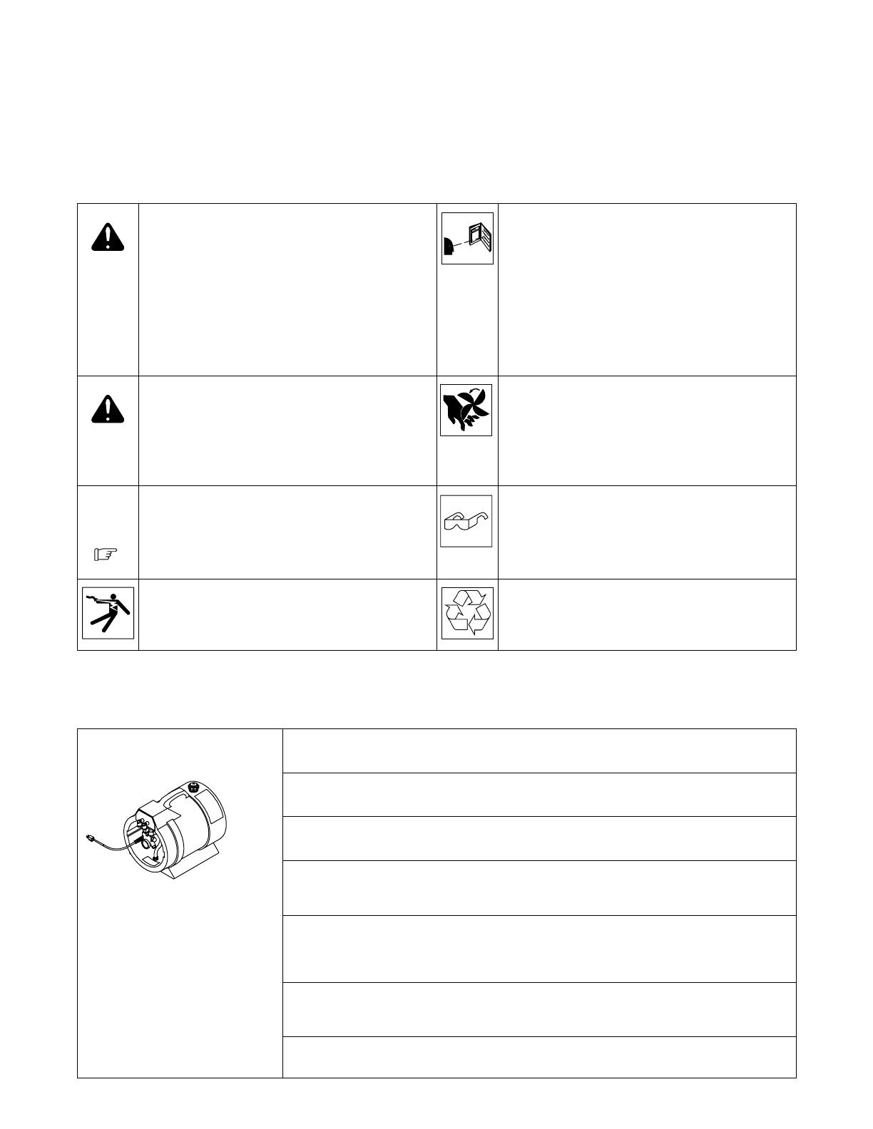
2. Specifications
Ref. 1228 574-B
Recirculating Coolant System For Water-Cooled GTAW Torches And GMAW Guns
Use With Guns/Torches Rated Up To 600 Amperes
IP Rating: 23 Not Intended For Use In Heavy Rain, Or Near Splashing Water
4 gal (15 L) Coolant Tank Capacity;
Maximum Cooling Capacity: 5,500 W (18,000 BTU/hr) @ 5.9 qt/min (5.6 L/min)
IEC Cooling Capacity: 1,780 W (6,070 BTU/hr) @ 1.1 qt/min (1 L/min)
IEC Cooling Capacity States That The Water Inlet Temperature Can Not Exceed 40° C Above Ambient
Temperature At A 1L/ Min Flow Rate.
Dimensions: 18-3/4 in. (476 mm) Long, 15-1/4 in. (387 mm) Wide, 16-1/4 in. (413 mm)
Weight: 44 lb (20 kg)
115 Volt, 5.9 Amperes 60 Hertz, 4.7 Amperes 50 Hertz, SinglePhase Input Power
OM-624 Page 2
3. Serial Number And Rating Label Location
The serial number and rating information for this product is located on the lower right side. Use rating label to determine input power requirements
and/or rated output. For future reference, write serial number in space provided on cover of this manual.
4. Warning Label Definitions For CE Products
S-180 663
1 2 3 4 5
6
7 8 9
1 Warning! Watch Out! There are
possible hazards as shown by the
symbols.
2 Electric shock from wiring can kill.
3 Disconnect input plug or power before
working on machine.
4 Moving parts, such as fans, can cut
fingers and hands and cause injury.
Keep away from moving parts.
5 Wear safety glasses with side shields.
6 Read the Owner’s Manual before
working on this machine.
7 Read the labels on the welding power
source, wire feeder, or other major
equipment for welding safety
information.
8 Recycle or dispose of used coolant in
an environmentally safe way.
9 Do not remove or paint over (cover)
the label.
OM-624 Page 3
4/96
S-178 910
=
043 810 (HF)
043 809 (AL)
100 h. std.
21 3
6
4
7
5
1 Warning! Watch Out! There are
possible hazards as shown by the
symbols.
2 Disconnect input plug or power before
working on machine.
3 Wear safety glasses with side shields.
4 Plugged filter or hoses cause
overheating and damage.
5 Read Owner’s Manual.
6 Check and clean filter every 100
hours; also check condition of hoses.
7 Use Low Conductivity Coolant No. 043
810 for High-Frequency assisted or
Gas Tungsten Arc Welding
applications. Use Aluminum Protecting
Coolant No. 043 809 where coolant
contacts aluminum parts or for Gas
Metal Arc Welding applications or
where High Frequency is not used.
1 Warning! Watch Out! There
are possible hazards as
shown by the symbols.
2 Moving parts, such as fans,
can cut fingers and hands and
cause injury. Keep away from
moving parts.
4/96
S-176 106
1
2
OM-624 Page 4
5. Symbols And Definitions
. Some symbols are found only on CE products.
A
Amperes Alternating Current
U
1
Primary Voltage Single Phase
V
Volts
Water (Coolant) In-
put
Water (Coolant)
Output
Line Connection
Hz
Hertz
IP
Degree Of
Protection
I
1
Primary Current
6. WEEE Label (For Products Sold Within The EU)
Do not discard product (where ap-
plicable) with general waste.
Reuse or recycle Waste Electrical
and Electronic Equipment (WEEE)
by disposing at a designated collec-
tion facility.
Contact your local recycling office
or your local distributor for further
information.
7. Preparing Cooling Unit For Use
160 554-A
1 Coolant Out Fitting
2 Coolant In Fitting
Fittings have 5/8-18 left-hand
threads.
Use table to select proper coolant,
and fill tank. Maintain coolant level
at approximately 1 in (25 mm) from
filler neck.
Unit turns On when plugged in.
Tools Needed:
5/8 in.
1
2
Low Conductivity Coolant
No. 043 810**;
Distilled Or Deionized Water
OK Above 32° F (0° C)
Low Conductivity Coolant
No. 043 810**; Or
Aluminum Protecting Coolant
No. 043 809**;
Distilled Or Deionized Water
OK Above 32° F (0° C)
GTAW Or Where
HF* Is Used
GMAW Or Where
HF* Is Not Used
Application
*HF: High Frequency Current
**Coolants 043 810 and 043 809 protect to -37° F (-38°C) and resist algae growth.
Coolant
Aluminum Protecting
Coolant No. 043 809**
Where Coolant Contacts
Aluminum Parts
OM-624 Page 5
8. Connections
160 556-A / 160 555-C
! Do not move or operate unit
where it could tip.
To prevent overheating, make sure
cooling unit is positioned so airflow
is not restricted.
NOTICE If welding power source
has a water valve, do not connect
hoses to water valve. Connect
hoses as shown.
GTAW Connections
GMAW Connections
OM-624 Page 6
9. Routine Maintenance
! Disconnect power
before maintaining.
1 Month
Clean Coolant Filter
Blow Out
Radiator Fins
6 Months
Replace
Cracked
Hoses
Replace
Unreadable
Labels
Change
Coolant (If
Using Water)
12 Months
Change
Coolant (If
Using 043 810
Or 043 809
Coolant)
10. Coolant Maintenance
1 Coolant Filter
Remove nut to remove filter. Clean
filter and reinstall.
Changing coolant: Drain coolant by
tipping unit. Fill with clean water and
run for 10 minutes. Drain and refill.
. If replacing hoses, use hoses
compatible with ethylene gly-
col, such as Buna-n, Neo-
prene, or Hypalon. Oxy-acety-
lene hoses are not compatible
with any product containing
ethylene glycol.
1
15/16 in.
Tools Needed:
160 559-A
OM-624 Page 7
Tools Needed:
11. Adjusting Relief Valve
160 558-B
. Relief valve is factory set at 60
psi (414 kPa), and normally
needs no adjustment: Only ad-
just if replacing motor.
1 Pressure gauge
2 Relief Valve Adjustment
Screw
Connect gauge to Coolant Out fit-
ting as shown. Block or plug any
output fitting on gauge.
Turn On power, and adjust pres-
sure adjustment screw as needed.
Turn Off power. Disconnect gauge
and reinstall nut.
3/4 in.
2
1
IncreaseDecrease
12. Troubleshooting
Trouble Remedy
Coolant system does not work. Be sure input power cord is plugged in to energized receptacle.
Check line fuses or circuit breaker, and replace or reset if necessary.
Motor overheated. Unit starts running when motor has cooled.
Have Factory Authorized Service Agent check motor.
Decreased or no coolant flow. Add coolant.
Check for clogged hoses or coolant filter.
Disconnect pump, and check for sheared coupling. Replace coupling if necessary.
13. Circuit Diagram
187 313
OM-624 Page 8
14. Parts List
1
Includes
Items
10&11
2
3
3
6
7
8
9
4
3
12
13
14
15
17
3
10
11
18
4
20
19
21
22
4
11
10
24
25
26
28
131 764-K
Figure 14-1. Complete Assembly
OM-624 Page 9
Description Quantity
Part
No.
Item
No.
Figure 14-1. Complete Assembly
1 124 377 WIRE FORM, radiator end 1. . . . . . . . . . . . . . . . . . . . . . . . . . . . . . . . . . . . . . . . . . . . . . . . . . . . . . . . . . .
2 127 904 RADIATOR, coolant tank w/weatherstripping (includes) 1. . . . . . . . . . . . . . . . . . . . . . . . . . . . . . . . . .
124 374 RADIATOR, coolant tank 1. . . . . . . . . . . . . . . . . . . . . . . . . . . . . . . . . . . . . . . . . . . . . . . . . . . . . . . . . . . . . .
159 594 WEATHERSTRIPPING, adh .250 x .750 x 3ft 4 in 1. . . . . . . . . . . . . . . . . . . . . . . . . . . . . . . . . . . . . . . . .
3 228 531 HOSE, rubber braided .375 ID X .650 OD X 12.000 SAE J20R3CLASS D2 2. . . . . . . . . . . . . .
4 236 084 HOSE, rubber braided .375 ID X .650 OD X 10.500 SAE J20R3CLASS D22. . . . . . . . . . . . . .
6 188 980 LABEL, caution incorrect coolant (non-CE and generic models) 1. . . . . . . . . . . . . . . . . . . . . . . . . . .
6 178 910 LABEL, caution incorrect coolant (CE models only) 1. . . . . . . . . . . . . . . . . . . . . . . . . . . . . . . . . . . . .
7 121 316 LABEL, warning general precautionary (non-CE and generic models) 1. . . . . . . . . . . . . . . . . . . . . .
7 180 663 LABEL, warning general precautionary (CE models only) 1. . . . . . . . . . . . . . . . . . . . . . . . . . . . . . . .
8 166 608 CAP, tank screw-on w/screw type vent 1. . . . . . . . . . . . . . . . . . . . . . . . . . . . . . . . . . . . . . . . . . . . . . . .
9 +139 154 TANK, coolant (includes) 1. . . . . . . . . . . . . . . . . . . . . . . . . . . . . . . . . . . . . . . . . . . . . . . . . . . . . . . . . . .
10 124 253 BUSHING, tank fuel 2. . . . . . . . . . . . . . . . . . . . . . . . . . . . . . . . . . . . . . . . . . . . . . . . . . . . . . . . . . . . . . .
11 124 621 FITTING, hose brs barbed 2. . . . . . . . . . . . . . . . . . . . . . . . . . . . . . . . . . . . . . . . . . . . . . . . . . . . . . . . .
12 130 633 INSULATOR, panel front 1. . . . . . . . . . . . . . . . . . . . . . . . . . . . . . . . . . . . . . . . . . . . . . . . . . . . . . . . . .
13 601 881 NUT, stl hex jam .500-20 2. . . . . . . . . . . . . . . . . . . . . . . . . . . . . . . . . . . . . . . . . . . . . . . . . . . . . . . . . .
14 231 241 WASHER, tooth .512 ID x .900 OD 2. . . . . . . . . . . . . . . . . . . . . . . . . . . . . . . . . . . . . . . . . . . . . . . . .
15 137 378 PLATE, ident 1. . . . . . . . . . . . . . . . . . . . . . . . . . . . . . . . . . . . . . . . . . . . . . . . . . . . . . . . . . . . . . . . . . . .
17 149 356 FITTING, hose brs barbed elb M 3/8tbg 2. . . . . . . . . . . . . . . . . . . . . . . . . . . . . . . . . . . . . . . . . . . . .
18 173 263 MOTOR, 1/4HP 115VAC 50/60 Hz 1425/1725RPM dual sha 1. . . . . . . . . . . . . . . . . . . . . . . . . . .
19 177 246 PUMP, coolant (includes) 1. . . . . . . . . . . . . . . . . . . . . . . . . . . . . . . . . . . . . . . . . . . . . . . . . . . . . . . . . .
20 5523 FITTING, hose brs barbed elb M 3/8tbg x 3/8NPT 2. . . . . . . . . . . . . . . . . . . . . . . . . . . . . . . . . . . . . . . .
21 134 795 COUPLER, drive pump 1. . . . . . . . . . . . . . . . . . . . . . . . . . . . . . . . . . . . . . . . . . . . . . . . . . . . . . . . . . . .
146 249 STRAINER, screen 100 x 90 mesh 2.125 lg x .687 1. . . . . . . . . . . . . . . . . . . . . . . . . . . . . . . . . . . . . . . .
22 144 649 CABLE, pwr 115V 16ga 3/c 13ft w/strain relief 1. . . . . . . . . . . . . . . . . . . . . . . . . . . . . . . . . . . . . . . .
24 194 099 BRACKET, mtg motor 1. . . . . . . . . . . . . . . . . . . . . . . . . . . . . . . . . . . . . . . . . . . . . . . . . . . . . . . . . . . . .
25 129 484 LABEL, warning moving parts can cause serious injury 1. . . . . . . . . . . . . . . . . . . . . . . . . . . . . . . .
26 132 987 BLADE, fan 10 in 6wg 23deg .500 bore CCW 1. . . . . . . . . . . . . . . . . . . . . . . . . . . . . . . . . . . . . . . .
28 245146 SPACER, fan 1. . . . . . . . . . . . . . . . . . . . . . . . . . . . . . . . . . . . . . . . . . . . . . . . . . . . . . . . . . . . . . . . . . . . .
+When ordering a component originally displaying a precautionary label, the label should also be ordered.
BE SURE TO PROVIDE MODEL AND SERIAL NUMBER WHEN ORDERING REPLACEMENT PARTS.
DECLARATION OF CONFORMITY
for European Community (CE marked) products.
MILLER Electric Mfg. Co., 1635 Spencer Street, Appleton, WI 54914 U.S.A. declares that
the product(s) identified in this declaration conform to the essential requirements and
provisions of the stated Council Directive(s) and Standard(s).
Product/Apparatus Identification:
Product Stock Number
COOLMATE 4 115VAC W/CE COMPLIANCE 042288015
Council Directives:
2006/95/EC Low Voltage
2004/108/EC Electromagnetic Compatibility
2006/42/EEC Machinery Directive
Standards:
IEC 609741 Arc Welding Equipment  Welding Power Sources: edition 3, 200507.
IEC 609742 Arc Welding Equipment  Liquid Cooling Systems: edition 1, 200206.
IEC 6097410 Arc Welding Equipment  Electromagnetic Compatibility Requirements: edition 1.1,
200410.
US Signatory:
December 19, 2008
__________________________________________________________________________
David A. Werba
Date of Declaration
MANAGER, PRODUCT DESIGN COMPLIANCE
Notes
Notes
  • Page 1 1
  • Page 2 2
  • Page 3 3
  • Page 4 4
  • Page 5 5
  • Page 6 6
  • Page 7 7
  • Page 8 8
  • Page 9 9
  • Page 10 10
  • Page 11 11
  • Page 12 12

Miller Coolmate 4 Le manuel du propriétaire

Catégorie
Système de soudage
Taper
Le manuel du propriétaire
Ce manuel convient également à

dans d''autres langues