Audio Authority Sona Flex SF-16B Mode d'emploi
- Catégorie
- Amplificateurs audio
- Taper
- Mode d'emploi

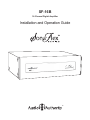
SF-16B
16-Channel Digital Amplier
Installation and Operation Guide
®

SF-16B Serial Number
Date of Purchase / Installation
Custom Installer
Telephone Number
DATE LTR REVISION RECORD AUTH DR CK
Part Number
Scale
Drawn By
Title
Date
Drawing No.
1:1
DAF
Rev.Sheet No.
Ink Color: White
Tolerance
--
1/2
1/2
701-13209
2006 Left Chassis Cover Artwork
F
20AN0620 3/17/10
7/30/10 A Release DAF
11/4/10 B Update fuse legend DAF
12/22/10 C Update fuse legend DAF
1/7/11 D Update fuse legend DAF
2/18/11 E New ETL mark, part dimensions DAF
3/21/11 F New ETL information DAF
Remplacer Uniquement
avec Fuse T 2.5A, 250Vac
Replace Fuse Only with
T 2.5A, 250Vac
ETL LISTED
CONFORMS TO
UL STD 60065
CERTIFIED TO
CAN/CSA STD C22.2 NO. 60065
4002715
100-125V~ 50-60 Hz 2.2A
701-13209F
This product has been tested by an accredited laboratory and meets the
provisions of FCC 47 CFR Part 15.
(b) Operation of an intentional, unintentional, or incidental radiator is
subject to the conditions that no harmful interference is caused and that
interference must be accepted that may be caused by the operation of an
authorized radio station, by another intentional or unintentional radiator,
by industrial, scientic and medical (ISM) equipment, or by an incidental
radiator.
(c) The operator of a radio frequency device shall be required to cease
operating the device upon notication by a Commission representative that
the device is causing harmful interference. Operation shall not resume until
the condition causing the harmful interference has been corrected.
Table Of Contents
Warnings .........................................3
Introduction .......................................5
Panel Descriptions ..................................6
Getting Started.....................................7
Connections .......................................8
Conguration .....................................14
Operation ........................................15
Using Ethernet, RS-232 and IR . . . . . . . . . . . . . . . . . . . . . . . 18
Appendix A: FlexPort Audio Transmitters ...............20
Appendix B: Updating Firmware ......................22
Appendix C: Rack Mounting . . . . . . . . . . . . . . . . . . . . . . . . . 22
Appendix D: Specications ..........................23
Limited Warranty ..................................23
Installation and Operation Guide
Model SF-16B
Audio Authority and the Double-A Symbol are registered trademarks of Audio Authority Corp. Copyright 2012, all rights reserved.
Lexington, Kentucky www.audioauthority.com 800-322-8346
®

SF-16B Digital Amplier Installation and Operation Guide 3
• Read these instructions.
• Keep these instructions.
• Heed all warnings.
• Follow all instructions.
• This product must be installed by qualied personnel.
• Do not open the cover—there are no user-serviceable
parts inside.
• Do not use this apparatus near water.
• Clean only with dry cloth.
• Make sure there is enough space around the unit for
cooling. Do not block any ventilation openings. Install in
accordance with the manufacturer’s instructions.
• Do not install near any heat sources such as radiators,
heat registers, stoves, or other apparatus (including
ampliers) that produce heat.
• Do not defeat the safety purpose of the grouding-type
plug. If the provided plug does not t into an outlet, consult
an electrician for replacement of the obsolete outlet.
• Before plugging the unit into a power socket, please make
sure you have selected the correct voltage.
• Protect the power cord from being walked on or pinched,
particularly at plugs, convenience receptacles, and the
point where it exits from the apparatus.
• Use only attachments/accessories specied by the
manufacturer.
• Unplug this apparatus during lightning storms or when
unused for long periods of time.
• Refer all servicing to qualied service personnel. Servicing
is required when the apparatus has been damaged in any
way, such as power-supply cord or plug is damaged, liquid
has been spilled or objects have fallen into the apparatus,
the apparatus has been exposed to rain or moisture, does
not operate normally, or has been dropped.
To reduce the risk of re or electric shock, do
not expose this apparatus to rain or moisture.
Pour réduire les risques d’incendie ou de choc électrique,
ne pas exposer cet appareil à la pluie ni à l’humidité.
• Liretouteslesdirectivesavantdemettrel’appareilenopération.
• Conserverlesdirectivesdesécuritéetd’utilisationpourfuture
consultation.
• Tenircomptedesavertissements.
• Suivrelesdirectives.
• Ceproduitdoitêtreinstalléparunpersonnelqualié.
• And’évitertoutrisqued’électrocution,nepasretirerlecapotoula
couvercle.Aucunedespiecesintérieuresn’estréparableparl’utilisateur.
Pourtouteréparation,s’adresseràuntechniciand’entretienqualié.
• Ne pas utiliser cet appareil près de l’eau.
• Nettoyerseulementavecunchionsec.
• Assurez-vousquelacirculationd’airautourdel’ampliestsusante.Les
ouverturesetfentesdanslechassissontprévuespourlaventilations
del’appareil.Cesouverturesnedoiventpasêtrebloquées.Installer
conformementauxdirectivesdumanufacturier.
• L’appareildoitêtresituéloindesourcesdechaleurtellesquedes
radiateurs,desregistresdechaleur,desfourneaux,oud’autresappareils
produisant de la chaleur.
• Nepasmodierledispositifdesecuritédelacheayantunebroche
demiseàlaterre.S’ilestimpossibled’insérerlachedanslaprisede
courant, contacter un électricien pour remplacer la prise de courant.
• AvantdereliervotreSF-16Bàlatensionsecteur,assurez-vousqu’ilest
réglé sur la tension adéquate.
• Lescordonsd’alimentationdevraientêtredisposésdefaçonàcequ’on
nepuissepasmarcherdessusouqu’ilssoientsusceptiblesd’êtrecoincés
par des articles placés sur ou contre eux. Une attention particulière doit
êtreportéeauxches,prisesdecourant,etauxpointsoùilssortentde
l’appareil.
• Utiliser seulement les attachements et accessoires recommandés par le
manufacturier.
• Débrancherl’appareildelaprised’alimentationpendantunorage
électriqueouuneabsenced’utilisationprolongée.
• Conertoutentretienàunpersonneldeservicequalié.
• Unserviced’entretienestnecéssairequandl’appareilnefonctionne
pasnormalementensuivantlesconsignesd’utilisation,quandlecordon
d’alimentationousachesontendommagés,quanddesobjetssont
tombésdansl’appareil,quandduliquideyaétèrenversé,ouquand
l’appareil a étè exposé à la pluie ou à l’eau.
!
!
WARNING: AVERTISSEMENT:
The lightning ash within an equilateral triangle is intended
to alert the user to the presence of uninsulated “dangerous
voltage” within the product’s enclosure that may be of
sufcient magnitude to constitute a risk of electric shock to
persons.
The exclamation point within an equilateral triangle is
intended to alert the user to the presence of important
operating and maintenance (servicing) instructions in the
literature accompanying the appliance.
L’éclairterminéd’uneècheàl’intérieurd’untriangleindiqueà
l’utilisateur la présence à l’intérieur de l’appareil d’une tension
dangereusenonisoléeayantuneamplitudesusantepour
provoqueruneélectrocution.
Lepointd’exclamationàl’intérieurd’untriangleindiquequedes
instructionsdefonctionnementetd’entretienimportantessont
detailléesdanslesdocumentsfournisavecl’appareil.
Lepointd’exclamationàl’intérieurdel’octagone
indique à l’utilisateur que des importantes
instructions d’opération et d’entretien sont incluses
dans ce document.
The exclamation point symbol within the eight-
sided shape alerts users to important operating
and maintenance instructions in this booklet.
1/2
1 2
3
4 5 6 7 8 9 10 11 12 13 14
15 16
SPEAKER OUTPUTS (CLASS 2 WIRING)
SERIAL
TRIGGER MODE
ALWAYS ON
BUS INPUT
1:1 INPUTS
701-13306
DB25 AUDIO INPUT
AUDIO LOOP OUTPUT
100-120V~ 50-60 Hz 1125W
Replace Fuses Only
with T 10A, 250V
Remplacer Uniquement avec
Fusible T 10A, 250V
Set voltage selector
and install correct
fuses according to
local power supply.
Régler le sélecteur
de tension et
installer les fusibles
corrects selon
l’alimentation locale.
4002715
ETL LISTED CONFORMS
TO UL STD 60065
CERTIFIED TO CAN/CSA
STD C22.2 NO. 60065
Audio Authority® Corp. • 2048 Mercer Rd. Lexington, KY 40511 USA
800-322-8346 • 859-233-4599 • www.audioauthority.com
Model SF-16 8-Zone Digital Amplifier
VOLTAGE SELECTOR
BUS
GAIN
L
R
A B C D E F G H
PDF User Manual
IN OUT
SYSTEM
TRIGGER
5V - 24V AC / DC
1/3
PDF User Manual

4 SF-16B Digital Amplier Installation and Operation Guide
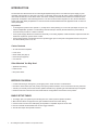
INTRODUCTION
The SonaFlex SF-16B combines an innovative digital amplier design with a rock solid linear power supply to yield
musicality and power like no other amp in its class. It is the basic version of the SF-16M, a matrix amplier with many
other advanced features, but the basic version has all the musicality and headroom that makes the SonaFlex series
popular with audiophiles. Built and designed in the U.S. with sound and video integrators in mind, the SF-16B offers
simple path to high delity amplication for commercial and residential distributed audio applications with or without a
matrix preamplier.
Key Features
• 16 analog RCA inputs that can operate 1:1 (usually with a matrix preamp) or in bus mode (all outputs on inputs 1,2).
• Class-D amplication provides a conservatively rated 45 watts per channel (all channels driven) or 60 watts (8
channels driven) at 8 Ohms - stable to 4 Ohms.
• Linear power supply delivers the warmth and musicality of an analog amplier, combined with the responsiveness and
headroom required for dynamic music content.
• Power saving features include automute and a system trigger input so that power management devices can put the
SF-16B in standby when not in use.
Carton Contents
• SF-16B 16-Channel Amplier
• Power Cord
• DB-25 cable (see page 8)
• Rack ears (see page 22)
• User manual
Other Materials You May Need
• Speakers and cabling
• Audio sources
• RCA patch cables
BEFORE YOU BEGIN
• Conrm that nothing is missing from your shipping carton. Refer to Carton Contents above.
• Record the serial number (see rear panel) in the space provided inside the cover of this manual for easy reference.
• Activate your warranty and receive rmware update notications by registering at www.audioauthority.com/register.
• Read this instruction manual to become familiar with the congurations and functions of this product.
BASIC SETUP TASKS
1. Thoroughly plan your system layout including wire runs, audio inputs and speaker locations.
2. Mount the SF-16B in an equipment rack; pull and label all audio and control cabling.
3. Connect audio sources to SF-16B input(s) and speakers to amplied outputs of the SF-16B.
4. Set Turn On Mode and Bus Mode and connect Trigger if desired.
4. Test all audio inputs at all speaker locations.

SF-16B Digital Amplier Installation and Operation Guide 5
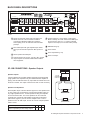
Quick connect audio inputs and loop outputs via
DB-25 connector. This connection is ideal for
connecting multiple SF-16B units to share the
same input(s) or for use with ADX and HLX matrix
preamps.
RCA audio inputs with gain adjustment per stereo
pair. Input A is the Bus Input when Bus Input is on
(E).
Stereo speaker-level Outputs.
System Trigger In & Out (5V - 24V AC / DC). Trigger
output may be connected to additional SF-16B or
other equipment.
Feature switches 1 and 2. Switch 1 sets Trigger
Mode or Always On mode. Switch 2 sets Bus Input
for use with one source, or 1:1 Inputs, individual
inputs for each output, for use with matrix preamp.
DB-9 RS-232 (p.8).
Power switch.
Fuse compartment (p.10).
Power cord input.
1/2
1 2
3 4 5 6 7 8 9 10 11 12 13 14
15 16
SPEAKER OUTPUTS (CLASS 2 WIRING)
SERIAL
TRIGGER MODE
ALWAYS ON
BUS INPUT
1:1 INPUTS
701-13306
DB25 AUDIO INPUT
AUDIO LOOP OUTPUT
100-120V~ 50-60 Hz 1125W
Replace Fuses Only
with T 10A, 250V
Remplacer Uniquement avec
Fusible T 10A, 250V
Set voltage selector
and install correct
fuses according to
local power supply.
Régler le sélecteur
de tension et
installer les fusibles
corrects selon
l’alimentation locale.
4002715
ETL LISTED CONFORMS
TO UL STD 60065
CERTIFIED TO CAN/CSA
STD C22.2 NO. 60065
Audio Authority® Corp. • 2048 Mercer Rd. Lexington, KY 40511 USA
800-322-8346 • 859-233-4599 • www.audioauthority.com
Model SF-16 8-Zone Digital Amplifier
VOLTAGE SELECTOR
BUS
GAIN
L
R
A B C D E F G H
PDF User Manual
IN OUT
SYSTEM
TRIGGER
5V - 24V AC / DC
1/3
PDF User Manual
BACK PANEL DESCRIPTIONS
A
A
B
B
D
D
C
C
E
E
F
F
H
G
G
I
I
H
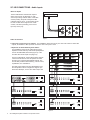
SF-16B CONNECTIONS - Speaker Outputs
Speaker Outputs
Connect speakers to removable speaker terminals using appropriate
gauge speaker wire. Speakers may be installed while the amplier is
playing. The SF-16B shuts down any output that has a dead short until
the short is cleared. The output comes back on with no reset necessary.
Speakers and Impedance
Each ampler output of the SF-16B can support a 4 Ohm speaker load.
In many cases only one speaker is connected per amplier output, so
any single speaker with a 4 - 8 Ohm impedance rating is acceptable
for use with the SF-16B. Two 8 ohm speakers can be connected
in parallel onto a single SF-16B amplier output without sacricing
performance (Figure 7). Do not connect multiple 6 ohm or 4 ohm
speakers to one SF-16B output, and do not connect multiple speakers
wired in series.
Speaker Impedance 8Ω 6Ω 4Ω
Max # of speakers per SF-16 amp output 2 1 1
SF-16B
SPEAKER
OUTPUT 1
SPEAKER A
SPEAKER B
+ –
+ –
1/2
1 2
3 4 5 6 7 8 9 10 11 12 13 14
15 16
SPEAKER OUTPUTS (CLASS 2 WIRING)
SERIAL
TRIGGER MODE
ALWAYS ON
BUS INPUT
1:1 INPUTS
701-13306
DB25 AUDIO INPUT
AUDIO LOOP OUTPUT
100-120V~ 50-60 Hz 1125W
Replace Fuses Only
with T 10A, 250V
Remplacer Uniquement avec
Fusible T 10A, 250V
Set voltage selector
and install correct
fuses according to
local power supply.
Régler le sélecteur
de tension et
installer les fusibles
corrects selon
l’alimentation locale.
4002715
ETL LISTED CONFORMS
TO UL STD 60065
CERTIFIED TO CAN/CSA
STD C22.2 NO. 60065
Audio Authority® Corp. • 2048 Mercer Rd. Lexington, KY 40511 USA
800-322-8346 • 859-233-4599 • www.audioauthority.com
Model SF-16 8-Zone Digital Amplifier
VOLTAGE SELECTOR
BUS
GAIN
L
R
A B C D E F G H
PDF User Manual
IN OUT
SYSTEM
TRIGGER
5V - 24V AC / DC
1/3
PDF User Manual
Figure 2 - Parallel speaker wiring
Figure 1

6 SF-16B Digital Amplier Installation and Operation Guide
Figure 3
Audio Connections
1. Input from a single source or switcher: For installations where there is only one source at a time for all SF-16B
outputs, set Switch 2 to Bus Input and connect the source to Inputs 1 and 2.
SF-16B CONNECTIONS - Audio Inputs
1/2
1 2
3
4 5 6 7 8 9 10 11 12 13 14
15 16
SPEAKER OUTPUTS (CLASS 2 WIRING)
SERIAL
TRIGGER MODE
ALWAYS ON
BUS INPUT
1:1 INPUTS
701-13306
DB25 AUDIO INPUT
AUDIO LOOP OUTPUT
100-120V~ 50-60 Hz 1125W
Replace Fuses Only
with T 10A, 250V
Remplacer Uniquement avec
Fusible T 10A, 250V
Set voltage selector
and install correct
fuses according to
local power supply.
Régler le sélecteur
de tension et
installer les fusibles
corrects selon
l’alimentation locale.
4002715
ETL LISTED CONFORMS
TO UL STD 60065
CERTIFIED TO CAN/CSA
STD C22.2 NO. 60065
Audio Authority® Corp. • 2048 Mercer Rd. Lexington, KY 40511 USA
800-322-8346 • 859-233-4599 • www.audioauthority.com
Model SF-16 8-Zone Digital Amplifier
VOLTAGE SELECTOR
BUS
GAIN
L
R
A B C
D E F G H
PDF User Manual
IN OUT
SYSTEM
TRIGGER
5V - 24V AC / DC
1/3
PDF User Manual
STEREO SOURCE
ADX-1616
SF-16B
SF-16B
SF-16B
SF-16B
SF-16B
HLX
Figure 4
Figure 5
RCA Line Inputs
The SF-16B includes 16 RCA audio inputs in
stereo pairs, and as an alternative, a quick
connect input using a DB-25 cable. If used with
a matrix preamp, all inputs correspond to like
numbered outputs, and 1:1 Input setting should
be used. If used with a single source or with
a switch, use Bus Input setting, and connect
Input A (1 and 2) only.
2. Input from an Audio Authority audio matrix:
For installations where the SF-16B is serving as an
amplier for Audio Authority audio matrix preampliers
such as the ADX-0808, ADX-1616 (Figure 4) or the
HLX with 2278 audio output card (Figure 5).
In these congurations, the SF-16B receives all audio
content from the ADX or HLX and passes the audio
through to the corresponding amplied outputs. The
HLX or ADX provides matrix switching, volume control,
equalization, tone and balance.
One ADX-1616 supports two SF-16B ampliers, and
the HLX platform can be congured to support up to
twelve SF-16B amps, one for each audio output card.

SF-16B Digital Amplier Installation and Operation Guide 7
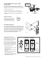
Changing the Power Fuse
Before changing the fuse, nd and correct
the excessive impedance load or wiring
short that caused the fuse failure.
The fuse compartment contains two extra
fuses that can be used to replace blown
fuses in the eld. Access the replacement
fuses by sliding out a compartment behind
each fuse, as shown in Figure 9.
• Remove the power cord.
• Carefully remove the fuse cover using a
at blade screwdriver.
• Inspect both fuses to determine which
one is blown.
• Replace the blown fuse with a spare fuse,
or a fuse of the same value.
• Orient the fuse cover so that the arrow
points toward the correct voltage for your
region as shown in Figure 9.
CAREFULLY PRY
WITH A SMALL
SCREWDRIVER
FUSE COVER
ARROW
INDICATES
VOLTAGE
200-240 Volts
(5A Fuses)
100-120 Volts
(10A Fuses)
SPARE
FUSE
ACTIVE
FUSES
Figure 9
Figure 8
Figure 7
SF-16B CONNECTIONS - System Trigger
(5V-24V AC/DC)
The System Trigger input on the SF-16B allows equipment such
as AV receivers or power managment devices to put the SF-16B in
standby when not in use, thereby greatly conserving energy usage.
To enable the System Trigger:
1. Make system trigger connections as illustrated in Figure 13.
2. Power the SF-16B, then apply power to the triggering device.
3. Set System Trigger DIP switch in the up (TRIGGER MODE)
position.
1/2
1 2
3
4 5 6 7 8 9 10 11 12 13 14
15 16
SPEAKER OUTPUTS (CLASS 2 WIRING)
SERIAL
TRIGGER MODE
ALWAYS ON
BUS INPUT
1:1 INPUTS
701-13306
DB25 AUDIO INPUT
AUDIO LOOP OUTPUT
100-120V~ 50-60 Hz 1125W
Replace Fuses Only
with T 10A, 250V
Remplacer Uniquement avec
Fusible T 10A, 250V
Set voltage selector
and install correct
fuses according to
local power supply.
Régler le sélecteur
de tension et
installer les fusibles
corrects selon
l’alimentation locale.
4002715
ETL LISTED CONFORMS
TO UL STD 60065
CERTIFIED TO CAN/CSA
STD C22.2 NO. 60065
Audio Authority® Corp. • 2048 Mercer Rd. Lexington, KY 40511 USA
800-322-8346 • 859-233-4599 • www.audioauthority.com
Model SF-16 8-Zone Digital Amplifier
VOLTAGE SELECTOR
BUS
GAIN
L
R
A B C D E F G H
PDF User Manual
IN OUT
SYSTEM
TRIGGER
5V - 24V AC / DC
1/3
PDF User Manual
TO NEXT SF-16B
SYSTEM TRIGGER
INPUT
Figure 6
POWER
MANAGEMENT
DEVICE
Serial Connection
Firmware updates are accomplished
via the serial port and a Windows
PC rmware update utility. Serial
connection pins are shown in Figure 7.
SF-16B Rack Mounting
The SF-16B is designed so that it may be installed either on a shelf
or in a standard 19-inch equipment rack. If rack mounting, remove
the feet and the cover screws adjacent to the front panel of the unit.
Reuse the cover screws to mount the rack adapters supplied with
the SF-16B. Be sure to place a spacer under the adapters at every
screw location. Secure the SF-16B to the rails of the equipment
rack with the screws supplied, and use appropriate chassis
supports, such as Middle Atlantic CSA Series.
1/2
1 2
3
4 5 6 7 8 9 10 11 12 13 14
15 16
SPEAKER OUTPUTS (CLASS 2 WIRING)
SERIAL
TRIGGER MODE
ALWAYS ON
BUS INPUT
1:1 INPUTS
701-13306
DB25 AUDIO INPUT
AUDIO LOOP OUTPUT
100-120V~ 50-60 Hz 1125W
Replace Fuses Only
with T 10A, 250V
Remplacer Uniquement avec
Fusible T 10A, 250V
Set voltage selector
and install correct
fuses according to
local power supply.
Régler le sélecteur
de tension et
installer les fusibles
corrects selon
l’alimentation locale.
4002715
ETL LISTED CONFORMS
TO UL STD 60065
CERTIFIED TO CAN/CSA
STD C22.2 NO. 60065
Audio Authority® Corp. • 2048 Mercer Rd. Lexington, KY 40511 USA
800-322-8346 • 859-233-4599 • www.audioauthority.com
Model SF-16 8-Zone Digital Amplifier
VOLTAGE SELECTOR
BUS
GAIN
L
R
A B C D E F G H
PDF User Manual
IN OUT
SYSTEM
TRIGGER
5V - 24V AC / DC
1/3
PDF User Manual
UP
1/2
1 2
3
4 5 6 7 8 9 10 11 12 13 14
15 16
SPEAKER OUTPUTS (CLASS 2 WIRING)
SERIAL
TRIGGER MODE
ALWAYS ON
BUS INPUT
1:1 INPUTS
701-13306
DB25 AUDIO INPUT
AUDIO LOOP OUTPUT
100-120V~ 50-60 Hz 1125W
Replace Fuses Only
with T 10A, 250V
Remplacer Uniquement avec
Fusible T 10A, 250V
Set voltage selector
and install correct
fuses according to
local power supply.
Régler le sélecteur
de tension et
installer les fusibles
corrects selon
l’alimentation locale.
4002715
ETL LISTED CONFORMS
TO UL STD 60065
CERTIFIED TO CAN/CSA
STD C22.2 NO. 60065
Audio Authority® Corp. • 2048 Mercer Rd. Lexington, KY 40511 USA
800-322-8346 • 859-233-4599 • www.audioauthority.com
Model SF-16 8-Zone Digital Amplifier
VOLTAGE SELECTOR
BUS
GAIN
L
R
A B C D E F G H
PDF User Manual
IN OUT
SYSTEM
TRIGGER
5V - 24V AC / DC
1/3
PDF User Manual
200V - 240V
100V - 120V
UP
5 4 3 2 1
9 8 7 6
GND RX TX
200V - 240V
100V - 120V

Power Per Channel (All Channels Driven): 45W @ 8 Ohms, 60W @ 4 Ohms
Power Per Channel (8 Channels Driven): 60W @ 8 Ohms, 80W @ 4 Ohms
Frequency Response: 20Hz to 20kHz, +/-1db into 8 Ohms
Full Power Bandwidth: 20Hz to 20kHz
S/N Ratio: 96dB
Channel Separation: 80dB(channel to channel @1kHz)
THD+N: <0.7% @ full power output
IMD: <0.5% @ full power output
Input Sensitivity: 0.5Vrms
Input Impedance: 10k Ohms
Audio Clock Frequency: 96KHz
Output Clock Frequency: 385KHz
Output Protection: Short Circuit, Over-Temperature, Overload
Line Voltage & Frequency: 100-120VAC 50-60Hz
200-240VAC 50Hz
Power Consumption: 1125W continuous, 1280W for 2 minutes
Maximum Current Draw:
5A RMS @ 240VAC
10A RMS @ 120VAC
Heat Output: 630 BTU/hr maximum
Dimensions (H x W x D): 5.22” x 16.60” x 14”
Net Weight: 41 lb.
Shipping Weight: 49 lb.
Approvals FCC, ETL
Warranty: Two years, parts and labor
SF-16B Specications
Limited Warranty
If this product fails due to defects in materials or workmanship within two years from the date of the original sale to the
end-user, Audio Authority guarantees that we will repair or replace the defective product at no cost. Freight charges
for the replacement unit will be paid by Audio Authority (Ground service only). A copy of the invoice from an Authorized
Re-seller showing the item number, serial number, and date of purchase (proof-of-purchase) must be submitted with
the defective unit to constitute a valid in-warranty claim.
Units that fail after the warranty period has expired may be returned to the factory for repair at a nominal charge, if not
damaged beyond the point of repair. All freight charges for out-of-warranty returns for repair are the responsibility of
the customer. Units returned for repair must have a Customer Return Authorization Number assigned by the factory.
This is a limited warranty and is not applicable for products which, in our opinion, have been damaged, altered,
abused, misused, or improperly installed. Audio Authority makes no other warranties either expressed or implied,
including limitation warranties as to merchantability or tness for a particular purpose. Additionally, there are no allow-
ances or credits available for service work or installation performed in the eld by the end user.
2048 Mercer Road, Lexington, Kentucky 40511-1071 USA
Phone: 859-233-4599 • Fax: 859-233-4510
Customer Toll-Free USA & Canada: 800-322-8346
www.audioauthority.com • support@audioauthority.com
752-639 v1.3.0 Rev. 20130516
®
-
 1
1
-
 2
2
-
 3
3
-
 4
4
-
 5
5
-
 6
6
-
 7
7
-
 8
8


Audio Authority Sona Flex SF-16B Mode d'emploi
- Catégorie
- Amplificateurs audio
- Taper
- Mode d'emploi
dans d''autres langues
Autres documents
-
Marantz PMD-706 Mode d'emploi
-
Yamaha 2602M Le manuel du propriétaire
-
Peavey Versamix Portable Mixing Console Le manuel du propriétaire
-
Sagem 155C Manuel utilisateur
-
Jensen VR187 Le manuel du propriétaire
-
-
 Benchmark AHB2 Black Manuel utilisateur
-
 ADVANCED NATIVE TECHNOLOGIES Start 16 HDM Manuel utilisateur
-
 Cotek Sc Series Manuel utilisateur
-
Kenwood KFC-X1720P Manuel utilisateur


