Cotek Sc Series Manuel utilisateur
- Catégorie
- Chargeurs de batterie
- Taper
- Manuel utilisateur

SC Series User’s Manual
SC-1200 / SC-2000
PURE SINE WAVE INVERTER CHARGER
EN
[Page 3]
SC-1200 / SC-2000
ONDULEURS-CHARGEURS PUR SINUS
FR
[Page 28]

EN
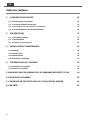
Table of Content
1. SAFETY INSTRUCTIONS 1
1-1. Warnings and symbols 1
1-2. Use for intended purpose general safety precautions 1
1-3. Other safety notes and installation precautions 1
1-4. Warning regarding the use of batteries 2
2. FUNCTION CHARACTERISTICS INTRODUCTION 3
2-1. System overview 3
2-2. Electrical specification 4
2-3. Mechanical drawings 8
3. INSTALLATION AND MAINTENANCE 9
3-1. Unpacking the product 9
3-2. Front panel 9
3-3. Rear panel 14
3-4. Mounting Instruction 18
4. SYSTEM FUNCTION INTRODUCTION 19
4-1. Battery charger introduction 19
4-2. Operation mode introduction 23
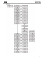
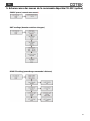
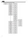
5. CR-20C MENU TREE 26
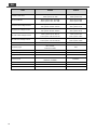
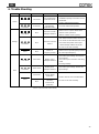
6. TROUBLE SHOOTING 29
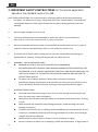
7. IMPORTANT SAFETY INSTRUCTIONS 30
8. WARRANTY 32

1
EN
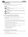
1. Safety Instructions
1-1. Warnings and symbols
Safety instructions and warnings are marked in this manual by the following pictograms:
Supplementary information on operating the device.
CAUTION
Safety instruction: Failure to observe this instruction can cause material damage and
impair the function of the device.
CAUTION
Safety instruction relating to a danger from an electrical current or voltage. Failure to
observe this instruction can cause material damage and personal injury and impair the
function of the device.
WARNING!
SAVE THESE INSTRUCTIONS – This manual contains important instructions that should
be followed during installation and maintenance of the unit.
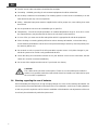
1-2. Use for intended purpose general safety precautions
The unit is constructed as per the applicable safety-technical guidelines.
For the charging of lead acid batteries and the supply of user attached to these batteries, in
permanent systems.
For the conversion of a DC voltage from a battery to and AC voltage.
Do not expose the unit to rain, snow, spray or dust. To reduce the risk of fire hazard, do not cover or
obstruct the ventilation openings and. do not install the unit in a zero-clearance compartment.
To avoid the risk of fire and electric shock, make sure that the existing wiring is in good electrical
condition; and that the wire size is not undersized.
Do not operate the unit with damaged or substandard wiring.
Depending on the use, the AC output of the unit may require user installed breaker or fusing. The
unit incorporates standard AC short circuit protection.
The following precautions should be taken when working on the Inverter Charger:
Remove watches, rings, or other metal objects.
Use tools with insulated handles.
Wear rubber gloves and boots.
1-3. Other safety notes and installation precautions
Upon receipt, examine the shipment box for damage. Notify the carrier immediately, before opening,
if damage is evident.
Do not operate near water or in excessive humidity.
Do not open or disassemble the unit, warranty may be voided.

2
EN
The DC and AC side connections should be firm and tight.
Grounding:Reliable grounding of rack-mounted equipment should be maintained.
Do not drop a metal tool on the battery. The resulting sparks or short-circuit on the battery or on the
other electrical part may cause an explosion.
Wiring:Adequate input power must be supplied to the unit for proper use; correct wiring sizes must
be ensured.
Do not operate the unit close to combustible gas or open fire.
Temperature:The unit should be operated in an ambient temperature range of -20 to 40°C or else
the output efficiency may be affected. Air flow to the unit must not be restricted.
In case of fire, you must use the fire extinguisher which is appropriate for electrical equipment.
Short circuiting or reversing polarity will lead to serious damage to batteries, unit and the wiring.
Fuses between the batteries and the unit cannot prevent damage caused by reversed polarity and
the warranty will be void.
Do not work on unit or system if it is still connected to a power source. Only allow changes in your
electrical system to be carried out by qualified electricians.
Check the wiring and connections at least once a year. Defects such as loose connections, burned
cables etc. must be corrected immediately.
Do not touch the equipment when wet or if your hands are clammy.
CAUTION
The cabinet of the unit must not be opened. There are no serviceable parts inside the
cabinet. Only qualified, authorized and trained electrician installers are authorized to open
the connection compartment.
1-4. Warning regarding the use of batteries
Excessive battery discharge and / or high charging voltage can cause serious damage to batteries. Do
not exceed the recommended limits of discharge level of your batteries. Avoid short circuiting batteries,
as this may result in explosion and fire hazard. Installation of the batteries and adjustments of the unit
should only be undertaken by authorized personnel!

3
EN
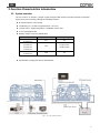
2. Function Characteristics Introduction
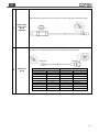
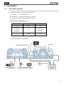
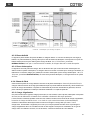
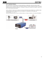
2-1. System overview
The SC Series is an inverter / charger system, designed with advanced power electronic and digital
signal processor technology offering the following features:
Bi-directional All-in-One Design.
Certified by UL ( UL458 & Supplement SA / UL1741 ).
Compact Size - Highly Integration = Installation hassle-free.
5-in-1 Operating Modes
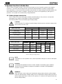
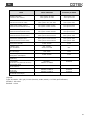
Battery charger current as below table.
Model No.
MAX
Battery voltage
SC1200-124
SC1200-224
25A
24V
SC1200-112
SC1200-212
SC2000-124
SC2000-224
50A
12V@SC1200
24V@SC2000
SC2000-112
SC2000-212
100A
12V
Table 1
:
SC series battery charger current
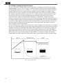
Equalization charging function for the batteries.
Fig. 1
:
SC series System Overview

4
EN
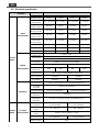
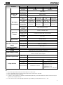
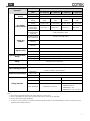
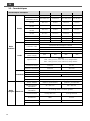
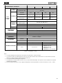
2-2. Electrical specification
Electrical
Specification
Model No.
Item
SC-1200-112
SC-1200-124
SC-1200-212
SC-1200-224
Inverter
Mode
Input
Characteristics
Nominal Voltage
12 VDC
24 VDC
12 VDC
24 VDC
Input Voltage
Range (±0.5V)
10.5 ~ 16.5 VDC
21 ~ 33 VDC
10.5 ~ 16.5 VDC
21 ~ 33 VDC
Input Over-Voltage
Protection (±0.5V)
16.5 VDC
33 VDC
16.5 VDC
33 VDC
Input Over-Voltage
Warning (±0.5V)
15.5 VDC
31 VDC
15.5 VDC
31 VDC
Input
Under-Voltage
Protection (±0.5V)
10.5 VDC
21 VDC
10.5 VDC
21 VDC
Input
Under-Voltage
Warning (±0.5V)
11.0 VDC
22.0 VDC
11.0 VDC
22.0 VDC
Input Current (Max)
132 A
66 A
132 A
66 A
No Load Current
< 3.0 A @12.5V
< 1.5 A @25V
< 3.0 A @12.5V
< 1.5 A @25V
Stand-By Current
< 0.4 A
< 0.2 A
< 0.4 A
< 0.2 A
Output
Characteristics
Continuous
Output Power
1200 VA ± 3%
Surge Power
Load 101%~115% (1 Min)
2400 VA (2 Sec)
Frequency
50/60 Hz ± 0.3 Hz (User-selectable)
Output Voltage
100 / 110 / 115 / 120VAC ±3%
200 / 220 / 230 / 240VAC ±3%
Max. Efficiency
(Full Load)
89%
90%
89%
90%
Output Waveform
Pure Sine Wave (THD < 5% @ 12.5V/25V/115VAC, linear load) /
(THD < 3% @ 12.5V/25V/230VAC, linear load)
INV. AC Output*
12A MAX
6A MAX
AC Output*
30A MAX
22A MAX
Protection
Input Protection
Over / Under Voltage, Reverse Polarity (Internal Fuse)
AC Output
Protection
Short-Circuit, Overload
AC Input Protection
30 Amp Circuit Breaker
16 Amp Circuit Breaker
Temperature
protection
Shutdown
Battery
Temperature
protection
By a RJ-11 connector to battery Temperature sensor
Charger
Mode
AC input
Characteristics
Nominal Voltage /
Frequency
110 VAC, 50 / 60Hz
(User-selectable)
230 VAC, 50 / 60Hz
(User-selectable)
Input Voltage
Range
90 ~ 132 VAC
180 ~ 264 VAC
Input Frequency
Range
50Hz:47 ~ 53 Hz / 60Hz:57 ~ 63 Hz
Nominal Current
8.2A (@110VAC)
3.9A (@230VAC)
Efficiency (Max.)
>88%

5
EN
Electrical
Specification
Model No.
Item
SC-1200-112
SC-1200-124
SC-1200-212
SC-1200-224
AC Input*
30 A MAX
16 A MAX
Power Factor
Correction(PFC)
>0.95 (Max.)
Auxiliary DC
Output
Output Voltage
Battery Voltage
Output Current
20A Max
DC Output
Characteristics
Charging Current
Range
12.5 / 25 / 37.5 /
50A
6.25 / 12.5 /
18.75 / 25A
12.5 / 25 / 37.5 /
50A
6.25 / 12.5 /
18.75 / 25A
Max. Output
Voltage
14.4 VDC
@ GEL TYPE
28.8 VDC
@ GEL TYPE
14.4 VDC
@ GEL TYPE
28.8 VDC
@ GEL TYPE
Battery
Temperature
Compensation
-25 mV per ℃
-50 mV per ℃
-25 mV per ℃
-50 mV per ℃
Battery Control
(3-stage Battery
Chargers)
Bulk / Absorption / Float
Signal and
Control
Remote Control
Panel (Optional)
CR-20C / CR-16B / CR-8
Remote Control
Terminal
Controls the inverter ON / OFF operation
Dry Contact
Terminal
By a relay
Bypass Relay
Relay Specification
30 Amp / 250 VAC
Transfer Time
0 sec
Operating Temperature
Range
Full Load
-20 ℃ ~ 50 ℃*
Power de-rating
40 W / ℃, 51~60 ℃
Storage
-30 ℃~70 ℃
Operating Humidity
Range
Max 93%, Non-condensing
Cooling
Temperature & Load Controlled Cooling Fan
Power Sharing Function
Inverter mode / Charger mode / Power sharing
Power Generator / Power support
Mechanical Specification
Dimension
(W x H x D)
251 x 116 x 386mm
Net Weight
4.55Kg
Safety and EMS
Safety Standards
UL458 & Supplement SA / UL1741
EN 62368-1
E-mark
---
Certified CISPR 25; ISO7637-2
EMC Standards
Certified FCC Class A*
EN55032 Class A*,
EN55024 Class A*
EN61000-3-2, 3-3
EN61000-4-2, 3, 4, 5, 6, 8, 11
Table 2. SC-Series Specification.
Note :
1. Max Inverter output define inverter 100% load output at Vac =100V / 200V
2. Max AC output define AC input current + Inverter output current, cannot over AC input limit.
3. Max AC input current Limit by the Breaker
4. SC series is a class A product. In a domestic environment this product may cause radio interference in which case the user may be
required to take adequate measures.
5. For SC-1200 -112 and -124, the operating temperature range certified by UL Safety Standard is -20°C ~ 40°C.

6
EN
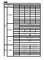
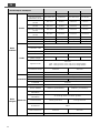
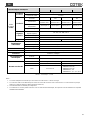
Electrical
Specification
Model No.
Item
SC-2000-112
SC-2000-124
SC-2000-212
SC-2000-224
Inverter
Mode
Input
Characteristics
Nominal Voltage
12 VDC
24 VDC
12 VDC
24 VDC
Input Voltage
Range (±0.5V)
10.5 ~ 16.5 VDC
21 ~ 33 VDC
10.5 ~ 16.5 VDC
21 ~ 33 VDC
Input Over-Voltage
Protection (±0.5V)
16.5 VDC
33 VDC
16.5 VDC
33 VDC
Input Over-Voltage
Warning (±0.5V)
15.5 VDC
31 VDC
15.5 VDC
31 VDC
Input
Under-Voltage
Protection (±0.5V)
10.5 VDC
21 VDC
10.5 VDC
21 VDC
Input
Under-Voltage
Warning (±0.5V)
11.0 VDC
22.0 VDC
11.0 VDC
22.0 VDC
Input Current (Max)
260 A
130 A
260 A
130 A
No Load Current
< 4.0 A @12.5V
< 2.0 A @25V
< 4.0 A @12.5V
< 2.0 A @25V
Stand-By Current
< 0.4 A
< 0.2 A
< 0.4 A
< 0.2 A
Output
Characteristics
Continuous Output
Power
2000 VA ± 3%
Surge Power
Load 101%~115% (1 Min)
4000 VA (2 Sec)
Frequency
50/60 Hz ± 0.3 Hz (User-selectable)
Output Voltage
100 / 110 / 115 / 120VAC ±3%
200 / 220 / 230 / 240VAC ±3%
Max. Efficiency
(Full Load)
89%
90%
89%
90%
Output Waveform
Pure Sine Wave (THD < 5% @ 12.5V/25V/115VAC, linear load) /
(THD < 3% @ 12.5V/25V/230VAC, linear load)
INV. AC Output*
20A MAX
10A MAX
AC Output*
30A MAX
26A MAX
Protection
Input Protection
Over / Under Voltage, Reverse Polarity (Internal Fuse)
AC Output
Protection
Short-Circuit, Overload
AC Input Protection
30 Amp Circuit Breaker
16 Amp Circuit Breaker
Temperature
protection
Shutdown
Battery
Temperature
protection
By a RJ-11 connector to battery Temperature sensor
Charger
Mode
AC input
Characteristics
Nominal Voltage /
Frequency
110 VAC, 50 / 60Hz
(User-selectable)
230 VAC, 50 / 60Hz
(User-selectable)
Input Voltage
Range
90 ~ 132 VAC
180 ~ 264 VAC
Input Frequency
Range
50Hz:47 ~ 53 Hz / 60Hz:57 ~ 63 Hz
Nominal Current
16.5A (@110VAC)
7.9A (@230VAC)
Efficiency (Max.)
>88%
AC Input*
30 A MAX
16 A MAX
Power Factor
Correction(PFC)
>0.95 (Max.)

7
EN
Electrical
Specification
Model No.
Item
SC-2000-112
SC-2000-124
SC-2000-212
SC-2000-224
Auxiliary DC
Output
Output Voltage
Battery Voltage
Output Current
20A Max
DC Output
Characteristics
Charging Current
Range
25 / 50 / 75 /
100A
12.5 / 25 / 37.5 /
50A
25 / 50 / 75 /
100A
12.5 / 25 / 37.5 /
50A
Max. Output
Voltage
14.4 VDC
@ GEL TYPE
28.8 VDC
@ GEL TYPE
14.4 VDC
@ GEL TYPE
28.8 VDC
@ GEL TYPE
Battery
Temperature
Compensation
-25 mV per ℃
-50 mV per ℃
-25 mV per ℃
-50 mV per ℃
Battery Control
(3-stage Battery
Chargers)
Bulk / Absorption / Float
Signal and
Control
Remote Control
Panel (Optional)
CR-20C / CR-16B / CR-8
Remote Control
Terminal
Controls the inverter ON / OFF operation
Dry Contact
Terminal
By a relay
Bypass Relay
Relay Specification
30 Amp / 250 VAC
Transfer Time
0 sec
Operating Temperature
Range
Full Load
-20 ℃ ~ 40 ℃
Power de-rating
60 W / ℃, 41~60 ℃
Storage
-30 ℃~70 ℃
Operating Humidity
Range
Max 93%, Non-condensing
Cooling
Temperature & Load Controlled Cooling Fan
Power Sharing Function
Inverter mode / Charger mode / Power sharing
Power Generator / Power support
Mechanical Specification
Dimension
(W x H x D)
251 x 116 x 453mm
Net Weight
6 Kg
Safety and EMS
Safety Standards
UL458 & Supplement SA / UL1741
EN 62368-1
E-mark
---
Certified CISPR 25; ISO7637-2
EMC Standards
Certified FCC Class A*
EN55032 Class A*,
EN55024 Class A*
EN61000-3-2, 3-3
EN61000-4-2, 3, 4, 5, 6, 8, 11
Table 3. SC-Series Specification
Note :
1. Max Inverter output define inverter 100% load output at Vac =100V / 200V
2. Max AC output define AC input current + Inverter output current, cannot over AC input limit.
3. Max AC input current Limit by the Breaker
4. SC series is a class A product. In a domestic environment this product may cause radio interference in which case the user may be
required to take adequate measures.

8
EN
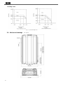
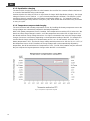
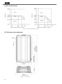
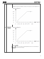
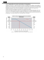
De-rating Curve
Fig. 2
:
SC series De-rating Curve
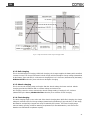
2-3. Mechanical drawings Unit : mm[inch]

9
EN
Fig. 3
:
SC series Mechanical drawings
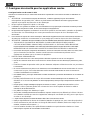
3. Installation and Maintenance
During installation and commissioning of the unit, the Safety Guidelines & Measures are applicable at all
times. See chapter 1 of this manual.
3-1. Unpacking the product
In addition to the unit the delivery includes:
Battery temperature sensor TS-01 ( optional )
Remote Control CR-20C ( optional or combo pack only )
Quick Instruction Guide
After unpacking, check the contents for possible damage. Do not use the product if it is damaged. In
case of the contents damaged, please contact your supplier.
Check from the identification label whether the battery voltage is the same as the DC-input voltage of the
unit (e.g. 12V battery set for a 12V input voltage). Also check that the AC output voltage and output
power of the unit satisfies loading requirements.
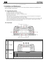
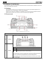
3-2. Front Panel
Fig. 4
:
SC series front panel introduction
Front panel
A
AC Output
Two 3/4 inch knockouts provided with cable-clamp strain reliefs to allow and hold the AC
input and output field wiring.
*If the grid power use GFCI or RCD socket, please set up the input current limit following
Front panel
1
AC Output terminal (L/N)
2
AC Input terminal (L/N)*
3
AC Input / Output ground terminal
B
AC Input
1
2
3

10
EN
their max current limitation for avoiding the risk of socket damage.
Model No.
AC IN AWG
AC OUT AWG
GROUNDING AWG
SC1200-112
30A/10AWG
30A/10AWG
30A/10AWG
SC1200-124
30A/10AWG
30A/10AWG
30A/10AWG
SC1200-212
16A/12AWG
22A/10AWG
22A/10AWG
SC1200-224
16A/12AWG
22A/10AWG
22A/10AWG
SC2000-112
30A/10AWG
30A/10AWG
30A/10AWG
SC2000-124
30A/10AWG
30A/10AWG
30A/10AWG
SC2000-212
16A/12AWG
26A/10AWG
26A/10AWG
SC2000-224
16A/12AWG
26A/10AWG
26A/10AWG
C
Chassis
ground
This connection is used to tie the exposed chassis of the inverter to the DC grounding
system. This terminal accepts CU/AL conductors from #14 to #2 AWG (2.1 to 33.6 mm2).
WARNING!
The ground wire offers protection only if the cabinet of the unit is
connected to the safety ground. Connect the chassis ground.
Terminal to the hull or the chassis.
Refer to local regulations on these issues!
For safety purposes the neutral conductor (N) of the AC output must be connected to the
earth (PE / GND) when the unit is in inverter operation. When utility power is available on
the AC input, and the unit is in charger mode, this connection must be disabled again.
In some applications automatic connection between the neutral conductor (N) and earth
(PE / GND) is not required or acceptable. Therefore the automatic connection between the
neutral conductor (N) and earth (PE / GND) is enabled by default.
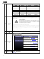
D
Main switch
The switch for 1.Power ON 2.Power Off 3.Remote Mode.
E
DIP switch
Dip Switch
Function
S1
Output Voltage Select (refer to 3-2-1-1)
S2
S3
Frequency Select (refer to 3-2-1-2)
S4
AC Input Current Limit Select
(refer to 3-2-1-3)
S5
S6
S7
Battery Type Select (refer to 3-2-1-4)
S8
S9
Charger Current Select (refer to 3-2-1-5)
S10
S11
DC Source on/off (refer to 3-2-1-6)
S12
Saving Function on/off (refer to 3-2-1-7)
F
Function LED
From left to right is “Battery voltage”’, ”AC output load”, “Charger stage”, “System status”
*For details, refer to 3-2-2
G
AC input
breaker

11
EN
Table 4
:
SC series front panel introduction
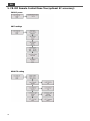
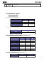
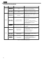
3-2-1. DIP(Function) switch:(reference E)
3-2-1-1 Output Voltage switch Function (S1,S2):
Output Voltage
S1
S2
100V / 200V
OFF
OFF
110V / 220V
ON
OFF
115V / 230V
OFF
ON
120V / 240V
ON
ON
Table 5
:
Output voltage function definition
3-2-1-2 Output Frequency switch Function (S3):
Frequency
S3
50HZ
OFF
60HZ
ON
Table 6
:
Output frequency function definition
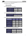
3-2-1-3 AC Input Current Limit Select (S4,S5,S6):Default : 15A/10A
AC Input Current
100~120V / 200~240V
S4
S5
S6
3A / 2A
OFF
OFF
OFF
6A / 4A
ON
OFF
OFF
9A / 6A
OFF
ON
OFF
12A / 8A
ON
ON
OFF
15A / 10A
OFF
OFF
ON
20A / 12A
ON
OFF
ON
25A / 14A
OFF
ON
ON
30A / 16A
ON
ON
ON
Table 7
:
SC series Input current limit select function definition
3-2-1-4 Battery Type Select Function(S7,S8):Default : GEL
Table 8
:
Battery types select function definition
Battery Type
S7
S8
GEL
OFF
OFF
Flooded
ON
OFF
AGM
OFF
ON
Customer
ON
ON

12
EN
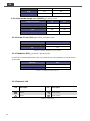
3-2-1-5 Charger current Select Function(S9,S10):Default : 100%
Charger Current (%)
S9
S10
25%
OFF
OFF
50%
ON
OFF
75%
OFF
ON
100%
ON
ON
Table 9
:
Charger current select function definition
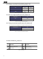
3-2-1-6 DC Source Output On/Off Function (S11):Default : OFF
ESB function
S11
OFF
OFF
ON
ON
Table 10
:
DC source output On/Off function definition
3-2-1-7 Saving Function Switch On/Off Function (S12):Default : OFF
The saving mode will be triggered if the output load <20W @10seconds.
Saving function
S12
OFF
OFF
ON
ON
Table 11
:
Saving function switch On/Off function definition
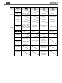
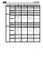
3-2-2 Status LED indicator:(reference F)
Icon
Description
Icon
Description
Battery Input voltage indicator
Output Load indicator
Alarm indicator
Charger Stage indicator
Table 12
:
LED indicator

13
EN
Status
LED
Indicator
Green
Off
Inverter mode
Solid ON
Normal
(12V: 11.5 ~ 15.0V)
(24V: 23.0 ~ 30.0V)
Normal
(0~100%)
Normal status
Float mode
Slow Blink
Over Temperature
Protection
Equalization mode
Fast Blink
Under Temperature
Protection
Active mode
Orange
Off
Inverter mode
Solid ON
Battery Low voltage
(12V:11.0 ~ 11.5V)
(24V:22.0 ~ 23.0V)
Battery High voltage
(12V:15.0 ~ 15.5V)
(24V:30.0 ~ 31.0V)
Over load
(100%-115%)
Phase or Frequency
Failure
Absorption mode
Slow Blink
Grid Over / Under
Voltage Protection
Bulk mode
Fast Blink
Grid Over Current
Protect
Red
Off
Inverter mode
Solid ON
Battery Under voltage
(12V: < 11.0V)
(24V: < 22.0V)
Battery Over voltage
(12V: >15.5V)
(24V: >31.0V)
Over load (>115%)
Over Load /
Short Circuit
Protection
Slow Blink
Battery Under
Voltage Protection
(12V: < 10.5V)
(24V: < 21.0V)
Fast Blink
Battery Over
Voltage Protection
(12V: >16.5V)
(24V: >33.0V)
Table 13
:
Status LED indicator

14
EN
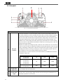
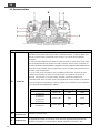
3-3. Rear panel
Fig. 5
:
SC series Rear panel introduction
Rear panel
A
DC input
connector
Follow the instructions to connect the battery cables to the DC input terminals of the unit.
The cables should be as short as possible (less than 6 feet / 1.8 meters ideally) so that they
can handle the required current in accordance with the Electrical Codes and Regulations.
The size of the cable should be thick enough to limit the voltage drop to less than 2% when
carrying the maximum input current to prevent frequent low-input voltage warnings, and
shutdown. UVP (Under Voltage Protection) warning may result if there is excessive voltage
drop across the DC cables between the batteries and the unit. Increasing your DC cable size
will help improve the situation.
Batteries are capable of providing very large currents in case of short circuit. In case there is
a short circuit in the cable run between the batteries and the input terminals of the unit, it will
result in overheating / melting of the cables and consequent risk of fire and injury, to prevent
possibility of this hazard, use Very Fast Acting DC Fuse in line with the positive cable. The
fuse should be as close to the positive battery terminal as possible.
The following sizes of cables and fuses are recommended for up to 6 ft. distance between
the batteries and the unit.
Model No.
Wire AWG
Inline Fuse
External Fuse
SC1200-124
SC1200-224
#6
100A
>100A
SC1200-112
SC1200-212
SC2000-124
SC2000-224
#2
200A
>200A
SC2000-112
SC2000-212
#2/0
400A
>400A
B
Auxiliary DC
output Fuse
Second charger limit current protection.
C
Auxiliary DC
output
SC series has a second charger output connector can be used to give a maintenance of a
small battery. Maximum current is 20A.
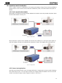
G

15
EN
D
Battery Temp.
sensor port
(RJ11)
(Optional)
When the battery temperature is high or low, the charge voltage will automatically adjust.
E
Remote port
(RJ11)
RS-232 Port:Serial port monitoring and control through computer interface.
SC Series
Computer
PIN Number
Description
PIN Number
Description
1
Not used
1
Not used
2
GND
2
RXD
3
RXD
3
TXD
4
TXD
4
Not used
5
Remo Control
5
GND
6
VCC
6
Not used
7
Not used
8
Not used
9
Not used

16
EN
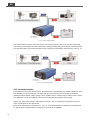
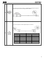
F
Remote control
terminal and
Dry terminal
Remote control terminal may be connected to a Form C relay for “FAULT” indication. When
“FAULT” occurs, the relay switches.
NOTE
Fault conditions include Input under/over voltage, Output Short Circuit, Over
Temperature, Over load and, Fan Failure.
Fig. 7
:
Remote control terminal
Item
Description
Item
Description
1
Dry contact
(Normal Open)
4
Enable+ (ENB)
2
Common
5
Enable- (ENB)
3
Dry contact
(Normal Closed)
6
Ground
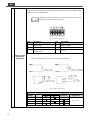
RS-232 / Remote control port
Use 20 ~ 24 #AWG wire to connect the remote control terminals.
Fig. 8
:
Wiring for remote control
Specifications of the Relay
Maximum
Voltage
Load
Contact Rating
Number of
operations
Operating/Storage
Temperature
N.O.
N.C.
250 VAC
Resistive
1 A
100,000
-30℃~75℃
250 VAC
Resistive
1 A
24 VDC
Resistive
1 A
24 VDC
Resistive
1 A

17
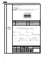
EN
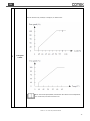
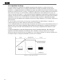
G
Fan speed
control
The fan turned on by Load(%) or Temp(°C) as below chart:
Note: the fan full speed(100%) turned when the status of over temperature,
the circuit short, and the over load occur
Table 16
:
SC series rear panel introduction

18
EN
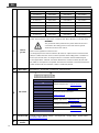
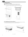
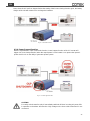
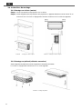
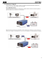
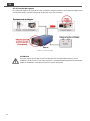
3-4. Mounting Instruction
3-4-1. Wall Mount ( For Marine )
Step 1. Use the screws to mount the Drip shield and the product on the wall.
Step 2. Please make sure the height from the ground to product at least 70 cm.
The bulkhead size requires at least 83 mm clearance each side of the inverter.
Fig. 6
:
Wall mount step 1 Fig. 7
:
Wall mount step 2
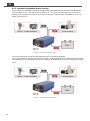
3-4-2. Ceiling Mount ( For Vehicle and Marine )
Use the screws to mount the product on the wall, and the product mounting requirement is as follow:
a. The mounting height from the ground to product requires at least 70 cm.
Fig. 8
:
Ceiling mount
La page est en cours de chargement...
La page est en cours de chargement...
La page est en cours de chargement...
La page est en cours de chargement...
La page est en cours de chargement...
La page est en cours de chargement...
La page est en cours de chargement...
La page est en cours de chargement...
La page est en cours de chargement...
La page est en cours de chargement...
La page est en cours de chargement...
La page est en cours de chargement...
La page est en cours de chargement...
La page est en cours de chargement...
La page est en cours de chargement...
La page est en cours de chargement...
La page est en cours de chargement...
La page est en cours de chargement...
La page est en cours de chargement...
La page est en cours de chargement...
La page est en cours de chargement...
La page est en cours de chargement...
La page est en cours de chargement...
La page est en cours de chargement...
La page est en cours de chargement...
La page est en cours de chargement...
La page est en cours de chargement...
La page est en cours de chargement...
La page est en cours de chargement...
La page est en cours de chargement...
La page est en cours de chargement...
La page est en cours de chargement...
La page est en cours de chargement...
La page est en cours de chargement...
La page est en cours de chargement...
La page est en cours de chargement...
La page est en cours de chargement...
La page est en cours de chargement...
La page est en cours de chargement...
La page est en cours de chargement...
La page est en cours de chargement...
La page est en cours de chargement...
La page est en cours de chargement...
La page est en cours de chargement...
La page est en cours de chargement...
La page est en cours de chargement...
La page est en cours de chargement...
La page est en cours de chargement...
La page est en cours de chargement...
-
 1
1
-
 2
2
-
 3
3
-
 4
4
-
 5
5
-
 6
6
-
 7
7
-
 8
8
-
 9
9
-
 10
10
-
 11
11
-
 12
12
-
 13
13
-
 14
14
-
 15
15
-
 16
16
-
 17
17
-
 18
18
-
 19
19
-
 20
20
-
 21
21
-
 22
22
-
 23
23
-
 24
24
-
 25
25
-
 26
26
-
 27
27
-
 28
28
-
 29
29
-
 30
30
-
 31
31
-
 32
32
-
 33
33
-
 34
34
-
 35
35
-
 36
36
-
 37
37
-
 38
38
-
 39
39
-
 40
40
-
 41
41
-
 42
42
-
 43
43
-
 44
44
-
 45
45
-
 46
46
-
 47
47
-
 48
48
-
 49
49
-
 50
50
-
 51
51
-
 52
52
-
 53
53
-
 54
54
-
 55
55
-
 56
56
-
 57
57
-
 58
58
-
 59
59
-
 60
60
-
 61
61
-
 62
62
-
 63
63
-
 64
64
-
 65
65
-
 66
66
-
 67
67
-
 68
68
-
 69
69


Cotek Sc Series Manuel utilisateur
- Catégorie
- Chargeurs de batterie
- Taper
- Manuel utilisateur
dans d''autres langues
- English: Cotek Sc Series User manual
Documents connexes
Autres documents
-
 Go Power! GP-IC2000-12-PKG Manuel utilisateur
-
ENERLITES 62081 Guide d'installation
-
Sterling Power Pro Combi S Pure Sine Wave Inverter Manuel utilisateur
-
Tripp Lite APSX2012SW Manuel utilisateur
-
Mercury 651.184 Le manuel du propriétaire
-
-
Samlexpower PST-1000-24 Le manuel du propriétaire
-
Mastervolt DC Master 24/24-7 (Isolated) Manuel utilisateur
-
-
