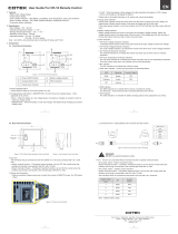
Cotek SD1500, SD2500, SD3500 Manuel utilisateur
- Catégorie
- Systèmes vidéo de voiture
- Taper
- Manuel utilisateur

SD Series User’s Manual
SD1500/2500/3500
PURE SINE WAVE INVERTER
EN
[Page 3]
SD1500/2500/3500
Signal de sortie sinusoïdal pur
FR
[Page 47]

Legal Provisions
Copyrights 2017 COTEK Electronic IND. CO. All Rights Reserved.
Any part of this document may not be reproduced in any form for any purpose without the prior
written permission of COTEK Electronic IND. CO. For the conditions of the permission to use this
manual for publication, contact COTEK Electronic IND. CO., LTD. In all related COTEK product
activities, Neither COTEK Electronic IND. CO., LTD. nor its distributors or dealers be liable to
anyone for indirect, incidental, or consequential damages under any circumstances. Specifications
are subject to change without notice. Every attempt has been made to make this document
complete, accurate and up-to-date. COTEK Electronic IND. CO., LTD reserve the right to make
changes without notice and shall not be responsible for any damages, including indirect, incidental
or consequential damages, caused by reliance on the material presented, including, but not limited
to, omissions, typographical errors, arithmetical errors or listing errors in the content material. All
trademarks are recognized even if these are not marked separately. Missing designations do not
mean that a product or brand is not a registered trademark.

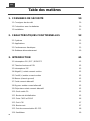
Table of Content
1. IMPORTANT SAFETY INFORMATION 1
1-1. General Safety Precautions 1
1-2. Precautions When Working with Batteries 1
1-3. Installation 2
2. FUNCTIONAL CHARACTERISTICS 3
2-1. General Information 3
2-2. Application 3
2-3. Electrical Performance 4
2-4. Mechanical Drawings 10
3. INTRODUCTION 12
3-1. Power ON / OFF / REMOTE (Main) switch 13
3-2. LED Indicator 13
3-3. DIP Switch (S1~S8) Assignment 14
3-4. DC Input - (please refer to DC wiring connections on P.20) 15
3-5. DC Input + (please refer to DC wiring connections on P.20) 16
3-6. Chassis Ground:Connect the wire # 8 AWG to vehicle chassis 16
3-7. AC Output (Please refer to hard wiring installation on P.21) 16
3-8. By-pass AC input (please refer to hard wiring installation on P.21) 16
3-9. AC input circuit breaker 16
3-10. AC output socket (please refer to 4-2-3. on P.24) 16
3-11. Reset Button (only to be used for Ethernet interface) 16
3-12. CAN1 and CAN2 Port (only to be used in parallel mode) 16
3-13. LCM Port 17
3-14. Green terminal (Remote and Parallel select) 18
3-15. RS-232 Port 19
3-16. Fan Ventilation 19
3-17. Protections Features 19

4. DC WIRING CONNECTIONS 20
4-1. DC Input Terminals 21
4-2. Hard-wire Installation 22
5. PARALLEL MODE 28
5-1. Prepare for Parallel Usage 28
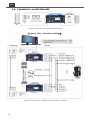
5-2. Industry Applications 29
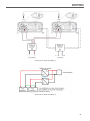
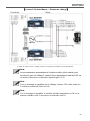
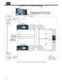
5-3. Wiring for Parallel Usage 31
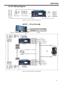
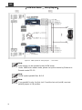
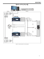
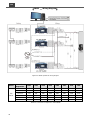
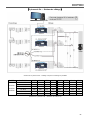
5-4. AC Wiring Diagram 33
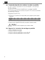
5-5. Remote command for the parallel connection 37
5-6. Remove Parallel Connection 37
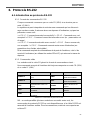
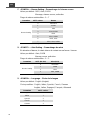
6. RS-232 COMMAND 38
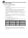
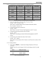
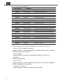
6-1. RS-232 command introduction 38
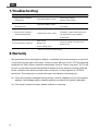
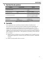
7. TROUBLESHOOTING 46
8. WARRANTY 46

1
1. Important Safety Information
WARNING!
Before using the inverter, read and save the safety instructions.
1-1. General Safety Precautions
1-1-1. Do not expose the Inverter to rain, snow, spray, bilge or dust.
To reduce risk of hazard, do not cover or obstruct the ventilation openings. Do
not install the inverter in a zero-clearance compartment. Overheating may
take place.
1-1-2. To avoid a risk of fire and electric shock, please make sure that existing wiring
is in good electrical condition; and that wire size is not undersized. Do not
operate the Inverter with damaged or substandard wiring.
1-1-3. This equipment contains components which can produce arcs or sparks.
To prevent fire or explosion do not install in compartments containing batteries
or flammable materials or in locations which require ignition protected
equipment. This includes any space containing gasoline-powered machinery,
fuel tanks, joints, fittings, or other connection between components of the fuel
system.
1-1-4. An over current protection at the time of installation shall be provided by
others for the AC output circuit.
1-1-5. Additional breakers suitable for 20 A branch circuit protection shall be
provided for the GFCI receptacles.
1-2. Precautions When Working with Batteries
1-2-1. If battery acid contacts skin or clothing, wash immediately with soap and water.
If acid enters eye, immediately wash eyes with running cold water for at least
20 minutes and get medical attention immediately.
1-2-2. Never smoke or allow a spark or flame in vicinity of battery or engine.
1-2-3. Do not drop a metal tool on the battery. The resulting spark or short-circuit on
the battery or other electrical part may cause an explosion.
1-2-4. Remove personal metal items such as rings, bracelets, necklaces, and
watches when working with a lead-acid battery.
A lead-acid battery produces a short-circuit current high enough to weld a ring
or similar item to metal causing a severe burn.

2
EN
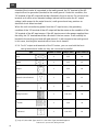
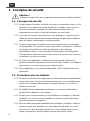
1-3. Installation
The power inverter should be installed in a location that meets the following
requirements:
Dry – Do not allow water to drip or splash on the inverter.
Cool – Ambient air temperature should be between -20℃ and 50℃, but he cooler
the better.
Safety – Do not install batteries in the compartment or other areas here flammable
fumes existence such as fuel storage areas or engine compartments.
Ventilated – Allow at least one feet of clearance around the Inverter for air flow.
Ensure the ventilation shafts on the rear and bottom of the unit are not
obstructed.
Dust-free – Do not install the Inverter in dusty environments here dust, wood
particles or other filings/shavings are present. The dust can be pulled
into the unit when the cooling fan is in operation.
Close to batteries – Avoid excessive cable lengths but do not install the inverter in
the same compartment as batteries.
Use the recommended wire lengths and sizes (refer to section 4.DC wiring
connections).
Do not mount the inverter where it is exposed to the gases produced by the battery.
These gases are very corrosive and prolonged exposure will damage the inverter.
WARNING!
Shock Hazard. Before proceeding further, carefully check that the inverter is
NOT connected to any batteries, and that all wiring is disconnected from any
electrical sources . Do not connect the output terminals of the inverter to an
incoming AC source.

3
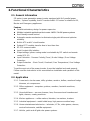
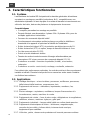
2. Functional Characteristics
2-1. General Information
SD-series is new generation power inverter equipped with N+1 parallel power
function , 3-phase capability, and AC transfer switch. SD series is suitable for RV,
Marine and Emergency appliances.
Features
Parallel redundancy design for power expansion
Multiple industrial applications that create 1Ф3W / 3Ф4W power systems
User-friendly remote control
Automatic master mechanism to eliminate single point failure and optimize
reliability
Built-in ATS and AC circuit breaker
Optional STS module, transfer time is less than 4ms.
RS-232 communication
Input & output fully isolation
Output voltage / power saving mode is selectable by DIP switch and remote
control (CR-10)
Input Protection:Reverse Polarity (Fuse) / Under Voltage / Over Voltage
Protection
Output Protection:Short Circuit / Overload / Over Temperature / Over Voltage
Protection
To get the most out of the power inverter, it must be installed and used properly.
Please read the instructions in this manual before installation and operation of this
model.
2-2. Application
2-2-1. Power tools–circular saws, drills, grinders, sanders, buffers, weed and hedge
trimmers, air compressors.
2-2-2. Office equipment – computers, printers, monitors, facsimile machines,
scanners.
2-2-3. Household items – vacuum cleaners, fans, fluorescent and incandescent
lights, shavers, sewing machines.
2-2-4. Kitchen appliances – coffee makers, blenders, ice markers, toasters.
2-2-5. Industrial equipment – metal halide lamp, high pressure sodium lamp.
2-2-6. Home entertainment electronics – television, VCRs, video games, stereos,
musical instruments, satellite equipment.
2-2-7. Vehicle, yacht and off-grid solar power systems.

4
EN
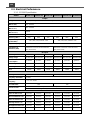
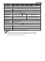
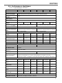
2-3. Electrical Performance
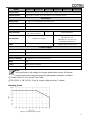
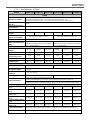
2-3-1. SD1500 Specification
MODEL
SD1500-112
SD1500-124
SD1500-148
SD1500-212
SD1500-224
SD1500-248
Output
Rating Power
1500VA (de-rating after 40°C, refer to de-rating curve)
Output Power
(Max. 3 min.)
1500~1800VA
Peak Power
(Max. 3 sec.)
1800~2400VA
Surge Power
(Max. 0.2 sec.)
>2400VA
Waveform
Pure Sine Wave
Efficiency (Max.)
88%
89%
90%
88%
88%
90%
Output Voltage
(@rated VDC)
100 / 110 / 115 / 120VAC ± 3%
200 / 220 / 230 / 240VAC ± 3%
Output Frequency
50 / 60Hz ± 0.1%
Total Harmonic
Distortion (THD)
< 3% @ under condition:
greater than 1.15 times of the rated VDC,
110V / linear load)
< 3% @ under condition:
greater than 1.15 times of the rated VDC,
230V / linear load)
DC Input
DC Voltage
12VDC
24VDC
48VDC
12VDC
24VDC
48VDC
Voltage Range
10.0~16.0 VDC
20.0~32.0 VDC
40.0~64.0 VDC
10.0~16.0 VDC
20.0~32.0 VDC
40.0~64.0 VDC
No load Power
Consumption
@12VDC
@24VDC
@48VDC
@12VDC
@24VDC
@48VDC
On Mode @ Save Mode
0.9A
0.5A
0.3A
1.1A
0.7A
0.4A
On Mode @ No Load Mode
< 2.4A
< 1.2A
< 0.6A
< 3.3A
< 1.6A
< 0.8A
Fuse
40Ax6
20Ax6
15Ax4
40Ax6
20Ax6
15Ax4
AC Input
AC Range
100 / 110 / 115 / 120VAC ± 12.5%
200 / 220 / 230 / 240VAC ± 12.5%
Frequency Selectable
50 / 60 Hz
Synchronous
Frequency
47~57 / 53~63 Hz
Circuit Breaker
20A
10A
Transfer Switch
①
Standard ATS:Inverter to utility AC:8~10ms.; Utility AC to inverter:16-50ms.
Optional STS Module : Single < 4ms ; N+1 & 1P3W & 3P4W < 6ms
Protection
BAT.Low Alarm ± 3%
10.5VDC
21.0VDC
42.0VDC
10.5VDC
21.0VDC
42.0VDC
BAT.Low Shut-down ± 3%
10.0VDC
20.0VDC
40.0VDC
10.0VDC
20.0VDC
40.0VDC
BAT.Low Restart ± 3%
12.5VDC
25.0VDC
50.0VDC
12.5VDC
25.0VDC
50.0VDC
BAT.High Alarm ± 3%
15.5VDC
31.0VDC
62.0VDC
15.5VDC
31.0VDC
62.0VDC
BAT.High Shut-down ± 3%
16.0VDC
32.0VDC
64.0VDC
16.0VDC
32.0VDC
64.0VDC
BAT.High Restart ± 3%
15.0VDC
30.0VDC
60.0VDC
15.0VDC
30.0VDC
60.0VDC
Input Protection
Reverse Polarity (Fuse) / Under Voltage / Over Voltage Protection / AC over current (Breaker)

5
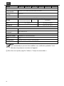
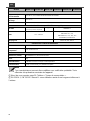
MODEL
SD1500-112
SD1500-124
SD1500-148
SD1500-212
SD1500-224
SD1500-248
Output Protection
Short Circuit / Overload / Over Temperature / Over Voltage Protection
Environment
Working Temp.
-20~+60°C; refer SD1500 power de-rating curve
Storage Temp.
-40~+70°C
Relative Humidity
Max. 90%, non-condensing
Safety & EMC
Safety Standards
Certified UL 458
(UL only for hardwire)
----
Certified EN 62368-1
EMC Standards
Certified FCC Class B
Certified EN55032, EN55024
E-Mark
----
Certified CISPR 25; ISO 7637-2
Control & Signal
LED Indicator
Input voltage level, faulty status
Remote Control
CR-6, CR-8 and CR-10
Others
Dimension (WxHxD)
283x128x351 mm / 11.14x5.04x13.82 inch
Weight
5.5 kg
Cooling
Load & Thermal control fan
Communication Port
RS-232 (RJ-11 type connector), Ethernet (Optional)
Note
The specifications are subject to change without prior notice. All the test
environments are conducted under the rated power operation conditions.
① Please refer to P. 10 Transfer-Time Table.

6
EN
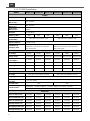
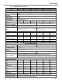
2-3-2. SD2500 Specification
MODEL
SD2500-112
SD2500-124
SD2500-148
SD2500-212
SD2500-224
SD2500-248
Output
Rating Power
2500VA (de-rating after 40°C, refer to de-rating curve)
Output Power
(Max. 3 min.)
2500~3000VA
Peak Power
(Max. 3 sec.)
3000~4000VA
Surge Power
(Max. 0.2 sec.)
>4000VA
Waveform
Pure Sine Wave
Efficiency (Max.)
88%
89%
90%
88%
88%
90%
Output Voltage
(@rated VDC)
100 / 110 / 115 / 120VAC ± 3%
200 / 220 / 230 / 240VAC ± 3%
Output Frequency
50 / 60Hz ± 0.1%
Total Harmonic
Distortion (THD)
< 3% @ under condition:
greater than 1.15 times of the rated VDC,
110V / linear load)
< 3% @ under condition:
greater than 1.15 times of the rated VDC,
230V / linear load)
DC Input
DC Voltage
12VDC
24VDC
48VDC
12VDC
24VDC
48VDC
Voltage Range
10.0~16.0 VDC
20.0~32.0 VDC
40.0~64.0 VDC
10.0~16.0 VDC
20.0~32.0 VDC
40.0~64.0 VDC
No load Power
Consumption
@12VDC
@24VDC
@48VDC
@12VDC
@24VDC
@48VDC
On Mode @ Save Mode
0.9A
0.5A
0.3A
1.1A
0.7A
0.4A
On Mode @ No Load Mode
< 3.2A
< 1.6A
< 1.0A
< 3.6A
< 1.8A
< 1A
Fuse
40Ax9
20Ax9
15Ax6
40Ax9
20Ax9
15Ax6
AC Input
AC Range
100 / 110 / 115 / 120VAC ± 12.5%
200 / 220 / 230 / 240VAC ± 12.5%
Frequency Selectable
50 / 60 Hz
Synchronous
Frequency
47~57 / 53~63 Hz
Circuit Breaker
35A
20A
Transfer Switch
①
Standard ATS:Inverter to utility AC:8~10ms.; Utility AC to inverter:16~50ms.
Optional STS module:Single < 4ms; N+1 & 1P3W & 3P4W < 6ms
Protection
BAT.Low Alarm ± 3%
10.5VDC
21.0VDC
42.0VDC
10.5VDC
21.0VDC
42.0VDC
BAT.Low Shut-down ± 3%
10.0VDC
20.0VDC
40.0VDC
10.0VDC
20.0VDC
40.0VDC
BAT.Low Restart ± 3%
12.5VDC
25.0VDC
50.0VDC
12.5VDC
25.0VDC
50.0VDC
BAT.High Alarm ± 3%
15.5VDC
31.0VDC
62.0VDC
15.5VDC
31.0VDC
62.0VDC
BAT.High Shut-down ± 3%
16.0VDC
32.0VDC
64.0VDC
16.0VDC
32.0VDC
64.0VDC
BAT.High Restart ± 3%
15.0VDC
30.0VDC
60.0VDC
15.0VDC
30.0VDC
60.0VDC

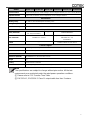
7
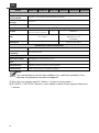
MODEL
SD2500-112
SD2500-124
SD2500-148
SD2500-212
SD2500-224
SD2500-248
Input Protection
Reverse Polarity (Fuse) / Under Voltage / Over Voltage Protection / AC over current (Breaker)
Output Protection
Short Circuit / Overload / Over Temperature / Over Voltage Protection
Environment
Working Temp.
-20~+60°C; refer SD2500 power de-rating curve
Storage Temp.
-40~+70°C
Relative Humidity
Max. 90%, non-condensing
Safety & EMC
Safety Standards
Certified UL 458
(UL only for hardwire)
----
Certified EN60950-1
EMC Standards
Certified FCC Class B
②
Certified EN 55014-1, EN 55014-2;
EN 61000-3-2, -3-3;
EN 62368-1
E-Mark
----
Certified CISPR 25; ISO 7637-2
Control & Signal
LED Indicator
Input voltage level, faulty status
Remote Control
CR-6, CR-8 and CR-10
Others
Dimension (WxHxD)
283x128x436 mm / 11.14x5.04x17.17 inch
Weight
8 kg
Cooling
Load & Thermal control fan
Communication Port
RS-232 (RJ-11 type connector), Ethernet (Optional)
Note
The specifications are subject to change without prior notice. All the test
environments are conducted under the rated power operation conditions.
① Please refer to P. 10 Transfer-Time Table.
② EN 55014-1, EN 55014-2 Class B: output cable less than 2 meters.

8
EN
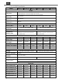
2-3-3. SD3500 Specification
MODEL
SD3500-112
SD3500-124
SD3500-148
SD3500-212
SD3500-224
SD3500-248
Output
Rating Power
3500W
(de-rating after 35°C, refer to de-rating curve for 12V)
(de-rating after 40°C, refer to de-rating curve for 24V and 48V)
Output Power
(Max. 3 min.)
3500~4500 W
Peak Power
(Max. 3 sec.)
4500~6000 W
Surge Power
(Max. 0.2 sec.)
>6000 VA
Waveform
Pure Sine Wave
Efficiency (Max.)
90%
90%
91%
90%
91%
91%
Output Voltage
(@rated VDC)
100 / 110 / 115 / 120VAC ± 3%
200 / 220 / 230 / 240VAC ± 3%
Output Frequency
50 / 60Hz ± 0.1%
Total Harmonic
Distortion (THD)
< 3% @ under condition:
greater than 1.15 times of the rated VDC,
110V / linear load)
< 3% @ under condition:
greater than 1.15 times of the rated VDC,
110V / linear load)
DC Input
DC Voltage
12VDC
24VDC
48VDC
12VDC
24VDC
48VDC
Voltage Range
10.0~16.0 VDC
20.0~32.0 VDC
40.0~64.0 VDC
10.0~16.0 VDC
20.0~32.0 VDC
40.0~64.0 VDC
No load Power
Consumption
@12VDC
@24VDC
@48VDC
@12VDC
@24VDC
@48VDC
On Mode @ Save Mode
1.4A
0.5A
0.5A
1.4A
0.5A
0.5A
On Mode @ No Load Mode
< 2.9A
< 1.4A
< 0.8A
< 3.6A
< 1.8A
< 1A
Fuse
40Ax12
20Ax12
20Ax6
40Ax12
20Ax12
20Ax6
AC Input
AC Range
100 / 110 / 115 / 120VAC ± 12.5%
200 / 220 / 230 / 240VAC ± 12.5%
Frequency Selectable
50 / 60 Hz
Synchronous
Frequency
47~57 / 53~63 Hz
Circuit Breaker
35A
20A
Transfer Switch
①
Standard ATS:Inverter to utility AC:8~10ms.; Utility AC to inverter:16~50ms.
Optional STS module:Single < 4ms; N+1 & 1P3W & 3P4W < 6ms
Protection
BAT.Low Alarm ± 3%
10.5VDC
21.0VDC
42.0VDC
10.5VDC
21.0VDC
42.0VDC
BAT.Low Shut-down ± 3%
10.0VDC
20.0VDC
40.0VDC
10.0VDC
20.0VDC
40.0VDC
BAT.Low Restart ± 3%
12.5VDC
25.0VDC
50.0VDC
12.5VDC
25.0VDC
50.0VDC
BAT.High Alarm ± 3%
15.5VDC
31.0VDC
62.0VDC
15.5VDC
31.0VDC
62.0VDC
BAT.High Shut-down ± 3%
16.0VDC
32.0VDC
64.0VDC
16.0VDC
32.0VDC
64.0VDC
BAT.High Restart ± 3%
15.0VDC
30.0VDC
60.0VDC
15.0VDC
30.0VDC
60.0VDC

9
MODEL
SD3500-112
SD3500-124
SD3500-148
SD3500-212
SD3500-224
SD3500-248
Input Protection
Reverse Polarity (Fuse) / Under Voltage / Over Voltage Protection / AC over current (Breaker)
Output Protection
Short Circuit / Overload / Over Temperature / Over Voltage Protection
Environment
Working Temp.
-20~+60°C; refer SD3500 power de-rating curve
Storage Temp.
-40~+70°C
Relative Humidity
Max. 90%, non-condensing
Safety & EMC
Safety Standards
Certified UL 458
(UL only for hardwire)
----
Certified EN60950-1
EMC Standards
Certified FCC Class B
②
Certified EN 55014-1, EN 55014-2;
EN 61000-3-2, -3-3;
EN 61000-6-1, -6-2, -6-3, -6-4
EN 62368-1, EN 61204-3
E-Mark
----
Certified CISPR 25; ISO 7637-2
Control & Signal
LED Indicator
Input voltage level, faulty status
Remote Control
CR-6, CR-8 and CR-10
Others
Dimension (WxHxD)
283x128x496 mm / 11.14x5.04x19.53 inch
Weight
10 kg
Cooling
Load & Thermal control fan
Communication Port
RS-232 (RJ-11 type connector), Ethernet (Optional)
Note
The specifications are subject to change without prior notice. All the test
environments are conducted under the rated power operation conditions.
① Please refer to P. 10 Transfer-Time Table.
② EN 55014-1, EN 55014-2 Class B: output cable less than 2 meters.
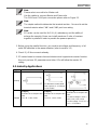
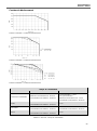
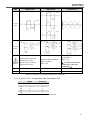
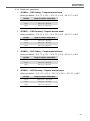
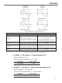
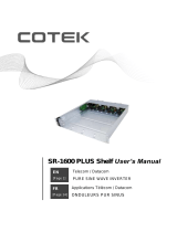
De-rating Curve
Figure 1. SD1500 de-rating curve

10
EN
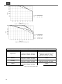
Figure 2. SD2500 de-rating curve
Figure 3. SD3500 de-rating curve
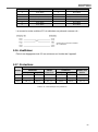
SD Series Transfer-Time Table
Mode / Transfer Switch
ATS
STS
Haphazard
Inverter to utility AC: 8~10ms.;
Utility AC to inverter: 16~50ms.
Frequency is synchronized: < 4ms.;
Frequency is not synchronized:
Inverter to utility AC: < 4ms.;
Utility AC to inverter: 16~50ms.
Normal
Inverter to utility AC: 8~10ms.;
Utility AC to inverter: 16~25ms.
< 4ms
Exacting
Inverter to utility AC: 8~10ms.;
Utility AC to inverter: 16~50ms.
Inverter to utility AC: < 4ms.;
Utility AC to inverter: 16~50ms.
Online
Inverter to utility AC: 16~25ms.;
Utility AC to inverter: 16~25ms.
< 4ms
Table 1. SD series transfer-time

11
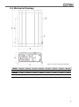
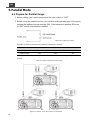
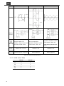
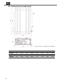
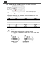
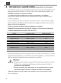
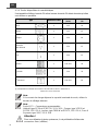
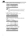
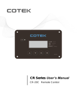
2-4. Mechanical Drawings
Figure 4. SD series mechanical drawings
Model
A (mm)
B (mm)
C (mm)
D (mm)
E (mm)
F (mm)
G (mm)
H (mm)
SD1500
351
160
93.1
268.6
8.5
11.5
128
283
SD2500
436
240.0
95.6
268.6
8.5
11.5
128
283
SD3500
496
240.0
125.6
268.6
8.5
11.5
128
283
Table 2. SD series dimension

12
EN
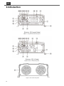
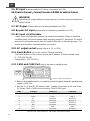
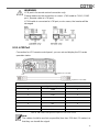
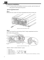
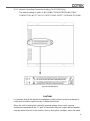
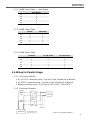
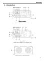
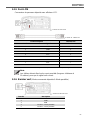
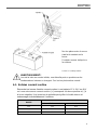
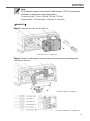
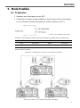
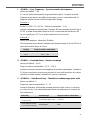
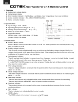
3. Introduction
【Version 1】General Model
Figure 5. SD general model front panel
【Version 2】UL Model
Figure 6. SD UL model front panel
Figure 7. SD series rear panel

13
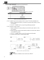
Front Panel / Rear Panel
1
Power ON/OFF/REMOTE (Main) switch
10
AC output socket
2
Status LED
11
Reset Button
3
Dip Switch (S1~S8)
12
CAN2 Port (only to be used in parallel mode)
4
DC Input -
13
CAN1 Port (only to be used in parallel mode)
5
DC Input +
14
LCM Port (Connection for LCD remote control
panel)
6
Chassis Ground
15
Green terminal (Remote and Parallel select)
7
AC Output
16
Remote / RS-232 port
8
By-pass AC Input
17
FAN
9
AC input circuit breaker
Table 3. SD front panel / rear panel introduction
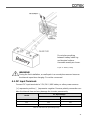
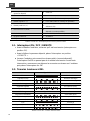
3-1. Power ON / OFF / REMOTE (Main) switch
A. Before installing the inverter, please ensure the main switch is in the OFF position.
B. Before using the remote unit, please ensure the main switch is in the REMOTE
position.
C. Main switch ON / OFF will not control AC Grid input, therefore for any
maintenances please remove the AC Grid connection to prevent damage of SD
series, then turn off the Main switch to OFF position for maintenance service.
3-2. LED Indicator
Green LED
LED Signal
Status
Solid
Power OK
Slow Blink
Power Saving
Intermittent Blink
Bypass
Orange LED
LED Signal
Status
Fast Blink
OVP
Slow Blink
UVP
Red LED
LED Signal
Status
Intermittent Blink
OTP
Fast Blink
OVP- Shut-down
Slow Blink
UVP- Shut-down
Solid
OLP
Intermittent Blink
Fan Failure
Intermittent Blink
Component Failure
Table 4. SD LED indicator

14
EN
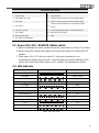
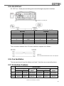
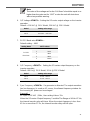
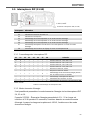
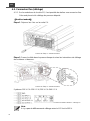
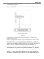
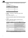
3-3. DIP Switch (S1~S8) Assignment
Figure 8. DIP switch (S1~S8)
PIN#
PIN Assignment
1
AC output voltage setting
2
AC output voltage setting
3
AC output frequency setting
4
To set-up 3 Phase output or Energy-saving level
5
To set-up 3 Phase output or Energy-saving level
6
To set-up 3 Phase output or Energy-saving level
7
To set-up DIP Switch S4~S6 for power saving or 3 Phase output
8
To set-up function parameters adjustment via LCM port or DIP switch
Table 5. DIP switch (S1~S8) PIN assignment
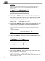
3-3-1. DIP switch set-up
S1
S2
S3
S4
S5
S6
S7
S8
Scenario
0
0
X
X
X
X
X
X
AC output voltage:100VAC/200VAC
1
0
X
X
X
X
X
X
AC output voltage:110VAC/220VAC
0
1
X
X
X
X
X
X
AC output voltage:115VAC/230VAC
1
1
X
X
X
X
X
X
AC output voltage:120VAC/240VAC
X
X
0
X
X
X
X
X
AC output frequency:50Hz
X
X
1
X
X
X
X
X
AC output frequency:60Hz
X
X
X
X
X
X
0
X
Power saving mode setting (S4~S6); No
master-slave in parallel
X
X
X
X
X
X
1
X
3 Phase output setting (S4~S6)
X
X
X
X
X
X
X
0
Adjust function parameters via LCM port
X
X
X
X
X
X
X
1
Adjust function parameters via DIP switch
1=ON / 0=OFF
Table 6. DIP switch set-up
3-3-2. Power Saving Mode
Power Saving Mode is adjustable and set by the Dip Switches,S4, S5 and S6 on the
front panel. Example SD2500:Saving set 2%, the load is below 50W 10 sec. will into
saving mode, more than 150W or more leave saving mode.
A. Power device enter the saving mode
The rate power x setting % = the threshold enter the power saving model
In case the load less than threshold value 10 seconds, the power device will enter
the saving mode.
1=ON/0=OFF

15
B. Power device leaving saving mode(re-start)
Restart threshold = rate power x setting % x 2~3
In case the power over the restart threshold, the power device will re-start and
provide the AC power.
S1
S2
S3
S4
S5
S6
S7
S8
Scenario
X
X
X
0
0
0
0
X
Power saving DISABLE
X
X
X
1
1
0
0
X
Go in power saving mode when output load is
under 4% of rating power
X
X
X
0
0
1
0
X
Go in power saving mode when output load is
under 5% of rating power
X
X
X
1
0
1
0
X
Go in power saving mode when output load is
under 6% of rating power
X
X
X
0
1
1
0
X
Go in power saving mode when output load is
under 7% of rating power
X
X
X
1
1
1
0
X
Go in power saving mode when output load is
under 8% of rating power
1=ON / 0=OFF
Table 7. Power saving mode set-up
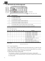
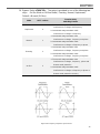
3-3-3. S4~S6 Set-up for parallel application
S1
S2
S3
S4
S5
S6
S7
S8
Scenario
X
X
X
0
0
0
1
X
Master (0°); "R" Phase
to be used for 1Ø 3W output in series
connection(Master) or 3Ø 4W output
connection("R" Phase)
X
X
X
0
0
1
1
X
Slave (0°) with current sharing
to be used in parallel connection only
X
X
X
0
1
1
1
X
Slave (180°), to be used for 1Ø 3W output in
series connection(L-NN-L)
X
X
X
1
0
0
1
X
Slave (-120°), "S" Phase
to support "S" Phase be(-120°) in 3Ø 4W
output connection
X
X
X
1
0
1
1
X
Slave (120°), "T" Phase
to support "T" Phase be(120°) in 3Ø 4W
output connection
X
X
X
1
1
1
1
X
Disable parallel function
1=ON / 0=OFF
Table 8. Parallel application set-up
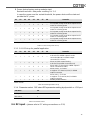
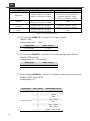
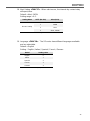
3-3-4. Parameter select: “S8” select SD’s parameter setting by dip switch or LCM port
Set Value
S8
LCM port
0
DIP switch
1
1=ON / 0=OFF
Table 9. Parameter select
3-4. DC Input - (please refer to DC wiring connections on P.20)

16
EN
3-5. DC Input + (please refer to DC wiring connections on P.20)
3-6. Chassis Ground:Connect the wire # 8 AWG to vehicle chassis
WARNING!
Operating the inverter without a proper ground connection may cause electrical
safety hazard.
3-7. AC Output (Please refer to hard wiring installation on P.22)
3-8. By-pass AC input (please refer to hard wiring installation on P.22)
3-9. AC input circuit breaker
The AC input circuit breaker protects the model from overload. When an overload
condition exists, the circuit breaker stops supplying output AC grid power. To reset it,
push the circuit breaker switch then the model will be back in normal operation. The
source fault should be corrected before you reset it.
3-10. AC output socket (please refer to 4-2-3. on P.24)
3-11. Reset Button (only to be used for Ethernet interface)
The Reset Button is to be used to resume the IP address to factory default value:
IP:192.168.100.181
Subnet Mask:255.255.255.0
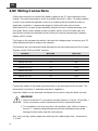
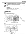
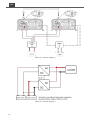
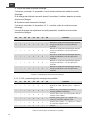
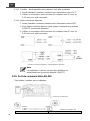
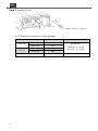
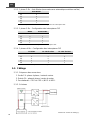
3-12. CAN1 and CAN2 Port (only to be used in parallel mode)
Figure 9. CAN1 and CAN2 port
1. Before using parallel mode, you need to ensure the green terminal’s parallel jump
status is set to ON.
2. Use the RJ-45 line (RJ-45 network cable:parallel connection) to link one of the
SD Series CAN1 (CAN2) port to the other CAN1 (CAN2) port.
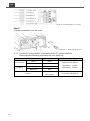
PIN#
LCM port
CAN1 port
CAN2 port
1
CANH
CAN_H
CAN_H
2
CANL
CAN_L
CAN_L
3
P1
Reserved
Reserved
4
VCC-
Reserved
Reserved
5
VCC+
Reserved
Reserved
6
DIS
Reserved
Reserved
7
5VS-
RND
RND
8
5VS+
Reserved
Reserved
Table 10. LCM, CAN1, CAN2 port
:
PIN number and signal description
La page est en cours de chargement...
La page est en cours de chargement...
La page est en cours de chargement...
La page est en cours de chargement...
La page est en cours de chargement...
La page est en cours de chargement...
La page est en cours de chargement...
La page est en cours de chargement...
La page est en cours de chargement...
La page est en cours de chargement...
La page est en cours de chargement...
La page est en cours de chargement...
La page est en cours de chargement...
La page est en cours de chargement...
La page est en cours de chargement...
La page est en cours de chargement...
La page est en cours de chargement...
La page est en cours de chargement...
La page est en cours de chargement...
La page est en cours de chargement...
La page est en cours de chargement...
La page est en cours de chargement...
La page est en cours de chargement...
La page est en cours de chargement...
La page est en cours de chargement...
La page est en cours de chargement...
La page est en cours de chargement...
La page est en cours de chargement...
La page est en cours de chargement...
La page est en cours de chargement...
La page est en cours de chargement...
La page est en cours de chargement...
La page est en cours de chargement...
La page est en cours de chargement...
La page est en cours de chargement...
La page est en cours de chargement...
La page est en cours de chargement...
La page est en cours de chargement...
La page est en cours de chargement...
La page est en cours de chargement...
La page est en cours de chargement...
La page est en cours de chargement...
La page est en cours de chargement...
La page est en cours de chargement...
La page est en cours de chargement...
La page est en cours de chargement...
La page est en cours de chargement...
La page est en cours de chargement...
La page est en cours de chargement...
La page est en cours de chargement...
La page est en cours de chargement...
La page est en cours de chargement...
La page est en cours de chargement...
La page est en cours de chargement...
La page est en cours de chargement...
La page est en cours de chargement...
La page est en cours de chargement...
La page est en cours de chargement...
La page est en cours de chargement...
La page est en cours de chargement...
La page est en cours de chargement...
La page est en cours de chargement...
La page est en cours de chargement...
La page est en cours de chargement...
La page est en cours de chargement...
La page est en cours de chargement...
La page est en cours de chargement...
La page est en cours de chargement...
La page est en cours de chargement...
La page est en cours de chargement...
La page est en cours de chargement...
La page est en cours de chargement...
La page est en cours de chargement...
La page est en cours de chargement...
La page est en cours de chargement...
La page est en cours de chargement...
La page est en cours de chargement...
La page est en cours de chargement...
La page est en cours de chargement...
La page est en cours de chargement...
-
 1
1
-
 2
2
-
 3
3
-
 4
4
-
 5
5
-
 6
6
-
 7
7
-
 8
8
-
 9
9
-
 10
10
-
 11
11
-
 12
12
-
 13
13
-
 14
14
-
 15
15
-
 16
16
-
 17
17
-
 18
18
-
 19
19
-
 20
20
-
 21
21
-
 22
22
-
 23
23
-
 24
24
-
 25
25
-
 26
26
-
 27
27
-
 28
28
-
 29
29
-
 30
30
-
 31
31
-
 32
32
-
 33
33
-
 34
34
-
 35
35
-
 36
36
-
 37
37
-
 38
38
-
 39
39
-
 40
40
-
 41
41
-
 42
42
-
 43
43
-
 44
44
-
 45
45
-
 46
46
-
 47
47
-
 48
48
-
 49
49
-
 50
50
-
 51
51
-
 52
52
-
 53
53
-
 54
54
-
 55
55
-
 56
56
-
 57
57
-
 58
58
-
 59
59
-
 60
60
-
 61
61
-
 62
62
-
 63
63
-
 64
64
-
 65
65
-
 66
66
-
 67
67
-
 68
68
-
 69
69
-
 70
70
-
 71
71
-
 72
72
-
 73
73
-
 74
74
-
 75
75
-
 76
76
-
 77
77
-
 78
78
-
 79
79
-
 80
80
-
 81
81
-
 82
82
-
 83
83
-
 84
84
-
 85
85
-
 86
86
-
 87
87
-
 88
88
-
 89
89
-
 90
90
-
 91
91
-
 92
92
-
 93
93
-
 94
94
-
 95
95
-
 96
96
-
 97
97
-
 98
98
-
 99
99
-
 100
100


Cotek SD1500, SD2500, SD3500 Manuel utilisateur
- Catégorie
- Systèmes vidéo de voiture
- Taper
- Manuel utilisateur
dans d''autres langues
Documents connexes
-
 Cotek SR-1600 PLUS series Manuel utilisateur
-
 Cotek SR-1600 PLUS series Manuel utilisateur
-
 Cotek CR-16 Manuel utilisateur
-
 Cotek SR-1600 (Shelf) Manuel utilisateur
-
 Cotek CR-20C Manuel utilisateur
-
 Cotek CR-6 Manuel utilisateur
-
 Cotek CX series Manuel utilisateur
-
 Cotek CX series Manuel utilisateur
-
 Cotek Sc Series Manuel utilisateur
-
 Cotek SE200, SE350, SE400 Manuel utilisateur


Autres documents
-
Mastervolt AC Master 12/3500 (230 V) Manuel utilisateur
-
Dometic SI 1500 24V Le manuel du propriétaire
-
HQ 12V-230V 2500W Manuel utilisateur
-
Olympus RF-11 Le manuel du propriétaire
-
Furrion FIVBDP10A Manuel utilisateur
-
Mastervolt AC Master 12/1000 Manuel utilisateur
-
Schneider Electric ATS48 Manuel utilisateur
-
Samlexpower PS1600-12 Le manuel du propriétaire
-
Eaton XC-CPU121-2C256K Instruction Leaflet
-
Extech Instruments 382075 Manuel utilisateur