Cotek SE200, SE350, SE400 Manuel utilisateur
- Taper
- Manuel utilisateur

SE Series User’s Manual
SE200 SE350 SE400
PURE SINE WAVE INVERTER
EN
[Page 1]
SE200 SE350 SE400
Onduleurs pur sinus
FR
[Page 17]
FR
[Page 26]


Legal Provisions
Copyrights 2017 COTEK Electronic IND. CO. All Rights Reserved.
Any part of this document may not be reproduced in any form for any purpose without the prior
written permission of COTEK Electronic IND. CO. For the conditions of the permission to use
this manual for publication, contact COTEK Electronic IND. CO., LTD. In all related COTEK
product activities, Neither COTEK Electronic IND. CO., LTD. nor its distributors or dealers be
liable to anyone for indirect, incidental, or consequential damages under any circumstances.
Specifications are subject to change without notice. Every attempt has been made to make this
document complete, accurate and up-to-date. COTEK Electronic IND. CO., LTD reserve the
right to make changes without notice and shall not be responsible for any damages, including
indirect, incidental or consequential damages, caused by reliance on the material presented,
including, but not limited to, omissions, typographical errors, arithmetical errors or listing errors
in the content material. All trademarks are recognized even if these are not marked separately.
Missing designations do not mean that a product or brand is not a registered trademark.


EN
Table of Content
1. SAFETY INSTRUCTIONS 1
1-1. General Safety Precautions 1
1-2. Other Safety Notes 2
2. FUNCTIONAL CHARACTERISTICS INTRODUCTION 3
2-1. System 3
2-2. Block Diagram 3
2-3. Electrical Specification 4
2-3-1. SE200 Specification 4
2-3-2. SE350 Specification 5
2-3-3. SE400 Specification 7
2-4. Mechanical Drawings 11
3. INSTALLATION AND MAINTENANCE 12
3-1. Front Panel Introduction 12
3-1-1. ON / OFF / Remote Main Switch 12
3-1-2. LED Indicator 12
3-1-3. AC Output 14
3-1-4. Function Switch 15
3-2. Rear Panel Introduction 16
3-2-1. DC Input Terminal 16
3-2-2. Green Terminal 17
3-2-3. Remote Port (RJ-11) 18
3-2-4. Chassis ground 19
3-3. Maintenance 19
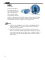
3-4. Inverter Installation and Operation 19

EN
4. OPERATION 21
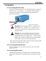
4-1. Connecting the DC Cable 21
4-2. Connecting the Input Power 21
4-3. Connecting the Loads 21
4-4. Switch ON Inverter 22
4-5. Protection Mechanism 22
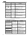
4-5-1. SE200 Protection Mechanism 22
4-5-2. SE350 protection mechanism 22
4-5-3. SE400 Protection Mechanism 23
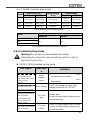
4-6. Troubleshooting Guide 23
5. WARRANTY 25
5-1 Warning 25
5-2 Warranty 25

1
1. Safety Instructions
1-1. General Safety Precautions
Warning! Before using the Inverter, read the safety
instructions.
Do not expose the inverter to rain, snow, spray or dust. To reduce
the risk of fire hazard, do not cover or obstruct the ventilation
openings and do not install the inverter in a zero-clearance
compartment.
To avoid the risk of fire and electric shock, make sure that the
existing wiring is in good electrical condition, and the wire size is
not undersized.
This equipment contains components which can produce arcs or
sparks. To prevent fire or explosion do not install in compartment
containing batteries or flammable materials or in location which
require ignition protected equipment. This includes any space
containing gasoline-powered machinery, fuel tanks, or joints,
fittings, or other connection between components of the fuel
system.
Depending on the user scenario, the AC output of the inverter
may require user installed breaker or fuse. In AC output hardwire
application, AC socket will not been provided. The inverter
incorporates standard AC short circuit protection.
An over current protection at the time of installation shall be
provided by others for the AC output circuit.
Additional breakers suitable for 20A(SE200 & SE350) /
10A(SE400) branch circuit protection shall be provided for the
GFCI receptacles.
The following precautions should be taken when working on the
inverter:
Step 1 Remove watches, rings, or other metal objects
Step 2 Use tools with insulated handles
Step 3 Wear rubber gloves and boots

2
EN
1-2. Other Safety Notes
Upon receipt, examine the carton box for damage. If you have
found any damage on the carton box please notify the company
you purchased this unit from.
Do not operate near water or in excessive humidity.
Do not open or disassemble the inverter, and warranty may be
voided.
The DC side connections should be firm and tight.
Grounding: Reliable grounding should be maintained.
Do not drop a metal tool on the battery. The resulting spark or
short-circuit on the battery or on the other electrical part may
cause an explosion.
Install the inverter in a well-ventilated area. Do not block the air
vents at the front AC output side, or the air exhausts at the rear
DC input side.
Wiring: Adequate input power must be supplied to the inverter for
proper use; correct wiring sizes must be ensured.
Mount the inverter such that the fan axis is horizontal.
Do not operate the inverter close to combustible gas or open fire.
Do not operate appliances that may feed power back into the
inverter.
The inverter should be operated in an ambient temperature
range:-20℃ to 60℃.
Otherwise the output efficiency may be affected. Air flow to the
inverter must not be blocked.

3
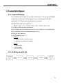
2. Functional Characteristics Introduction
2-1. System
The unit is a highly reliable DC-AC inverter system, designed with
advanced power electronic and microprocessor technology offering
the following features:
Pure sine wave output waveform:
SE200:THD < 3 % / SE350:THD < 3 % / SE400:THD < 5 %
Intelligent software for power management
Loading and temperature controlled cooling fan
CR-8 remote management and control
Dry contact terminal
Advanced protection features
Input protection
Over/Under voltage protection
Reverse polarity protection (Fuse)
Output protection
Overload protection
Over temperature protection
Short circuit protection
2-2. Block Diagram

4
EN
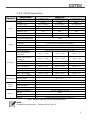
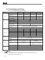
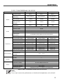
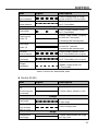
2-3. Electrical Specification
2-3-1. SE200 Specification
Electrical
Specification
Model No.
Item
SE200-112
SE200-124
SE200-212
SE200-224
Input
Voltage
12VDC
24VDC
12VDC
24VDC
Voltage Range
10.0~16.0VDC
20.0~32.0VDC
10.0~16.0VDC
20.0~32.0VDC
No Load Current
< 0.5A
< 0.4A
< 0.5A
< 0.4A
Power Saving Mode
< 0.12A
< 0.06A
< 0.12A
< 0.06A
Efficiency (Typ.)
89%
91%
91%
93%
On Mode @ Saving Mode
< 0.12A
< 0.06A
< 0.12A
< 0.06A
On Mode @ No Load Mode
< 0.5A
< 0.4A
< 0.5A
< 0.4A
Output
Continuous Output Power
200 W
Over Rated Power
(3 Min.)
230 W
Peak Power (3 Sec.)
250 W
Frequency
50 / 60 Hz ± 0.5% (Dip Switch Selectable)
Output Voltage
100 / 110 / 115 / 120 VAC ± 5%
(Dip Switch Selectable)
200 / 220 / 230 / 240 VAC ± 5%
(Dip Switch Selectable)
Short-Circuit Protection
2 seconds and restart 3 times shutdown
Output Waveform
Pure Sine Wave (THD < 3%@ Normal Load)
Protection
Input Over-Voltage
Protection
16.0VDC ± 3%
32.0VDC ± 3%
16.0VDC ± 3%
32.0VDC ± 3%
Input Under-Voltage
Protection
10.0VDC ± 3%
20.0VDC ± 3%
10.0VDC ± 3%
20.0VDC ± 3%
BAT. Low Shutdown
10.0VDC ± 3%
20.0VDC ± 3%
10.0VDC ± 3%
20.0VDC ± 3%
BAT. Low Alarm
10.5VDC ± 3%
21.0VDC ± 3%
10.5VDC ± 3%
21.0VDC ± 3%
BAT. Low Restart
12.5VDC ± 3%
25.0VDC ± 3%
12.5VDC ± 3%
25.0VDC ± 3%
BAT. High Alarm
15.5VDC ± 3%
31.0VDC ± 3%
15.5VDC ± 3%
31.0VDC ± 3%
BAT. High Shutdown
16.0VDC ± 3%
32.0VDC ± 3%
16.0VDC ± 3%
32.0VDC ± 3%
BAT. High Restart
14.5VDC ± 3%
29.0VDC ± 3%
14.5VDC ± 3%
29.0VDC ± 3%
Environment
Working Temp.
-20 ℃~60 ℃
Storage Temp.
-30 ℃~70 ℃
Working Humidity
10~95% RH, non-condensing
Safety &
EMC
Safety Standards
UL 458 (UL only for SE400 GFCI
receptacles)
Certified EN 62368-1
EMC standards
Certified FCC class B
Certified EN55032 class B;
EN61000-3-2, -3-3; EN55024
IEC61000-4-2, 3, 4, 5, 6, 8, 11
E-mark
----
Certified CISPR 25; ISO 7637-2
Others
Dimension(WxHxD)
150 mm X 68mm X187 mm
Weight
1.6kg
Remote Control
CR-8 (optional)
Cooling
Temperature & Load Controlled cooling Fan
Table 1. SE200 specification
Note:
This test condition is normal DC input and temperature 25℃

5
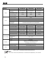
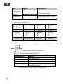
2-3-2. SE350 Specification
Electrical
Specification
Model No.
Item
SE350-112
SE350-124
SE350-148
Input
Voltage
12VDC
24VDC
48VDC
Voltage Range
10.0~15.5VDC
20.0~31.0VDC
40.0~62.0VDC
No Load Current
< 0.65A
< 0.32A
< 0.16A
Power Saving Mode
< 90mA
< 60mA
< 40mA
Efficiency (Typ.)
87%
88%
89%
On Mode @ Saving Mode
< 90mA
< 60mA
< 40mA
On Mode @ No Load Mode
< 0.65A
< 0.32A
< 0.16A
Output
Continuous Output Power
350 W
Surge Power
700 W
Frequency
50 / 60 Hz ± 0.1% (Dip Switch Selectable)
Output Voltage
100 / 110 / 115 / 120 VAC ± 5% (Dip Switch Selectable)
Short-Circuit Protection
2 seconds and restart 4 times shutdown
Output Waveform
Pure Sine Wave (THD < 3%@ Normal Load)
Protection
Input Over-Voltage
Protection
15.5V ± 0.25V
31.0V ± 0.5V
62.0V ± 1V
Input Under-Voltage
Protection
10.0V ± 0.25V
20.0V ± 0.5V
40.0V ± 1V
BAT. Low Shutdown
10.0V ± 0.25V
20.0V ± 0.5V
40.0V ± 1V
BAT. Low Alarm
10.5V ± 0.25V
21.0V ± 0.5V
42.0V ± 1V
BAT. Low Restart
12.0V ± 0.25V
24.0V ± 0.5V
48.0V ± 1V
BAT. High Alarm
15.0V ± 0.25V
30.0V ± 0.5V
60.0V ± 1V
BAT. High Shutdown
15.5V ± 0.25V
31.0V ± 0.5V
62.0V ± 1V
BAT. High Restart
14.5V ± 0.25V
29.0V ± 0.5V
58.0V ± 1V
Environment
Working Temp.
Note
-20 ℃~60 ℃
Storage Temp.
-30 ℃~70 ℃
Working Humidity
90% RH, non-condensing
Safety &
EMC
Safety Standards
----
EMC standards
----
E-mark
----
Others
Dimension(WxHxD)
150 mm X 68mm X187 mm
Weight
1.6kg
Remote Control
CR-8 (optional)
Cooling
Temperature & Load Controlled cooling Fan
Table 2. SE350 for output 100/110/115/120 VAC specification
Note:
Temperature performance:Please refer to Figure 1

6
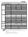
EN
Electrical
Specification
Model No.
Item
SE350-212
SE350-224
SE350-248
Input
Voltage
12VDC
24VDC
48VDC
Voltage Range
10.0~15.5VDC
20.0~31.0VDC
40.0~62.0VDC
No Load Current
< 0.9A
< 0.5A
< 0.25A
Power Saving Mode
< 90mA
< 60mA
< 40mA
Efficiency (Typ.)
89%
90%
91%
On Mode @ Saving Mode
< 90mA
< 60mA
< 40mA
On Mode @ No Load Mode
< 0.9A
< 0.5A
< 0.25A
Output
Continuous Output Power
350 W
Surge Power
700 W
Frequency
50 / 60 Hz ± 0.1% (Dip Switch Selectable)
Output Voltage
200 / 220 / 230 / 240 VAC ± 5% (Dip Switch Selectable)
Short-Circuit Protection
2 seconds and restart 4 times shutdown
Output Waveform
Pure Sine Wave (THD < 3%@ Normal Load)
Protection
Input Over-Voltage
Protection
15.5V ± 0.25V
31.0V ± 0.5V
62.0V ± 1V
Input Under-Voltage
Protection
10.0V ± 0.25V
20.0V ± 0.5V
40.0V ± 1V
BAT. Low Shutdown
10.0V ± 0.25V
20.0V ± 0.5V
40.0V ± 1V
BAT. Low Alarm
10.5V ± 0.25V
21.0V ± 0.5V
42.0V ± 1V
BAT. Low Restart
12.0V ± 0.25V
24.0V ± 0.5V
48.0V ± 1V
BAT. High Alarm
15.0V ± 0.25V
30.0V ± 0.5V
60.0V ± 1V
BAT. High Shutdown
15.5V ± 0.25V
31.0V ± 0.5V
62.0V ± 1V
BAT. High Restart
14.5V ± 0.25V
29.0V ± 0.5V
58.0V ± 1V
Environment
Working Temp.
Note
-20 ℃~60 ℃
Storage Temp.
-30 ℃~70 ℃
Working Humidity
90% RH, non-condensing
Safety &
EMC
Safety Standards
Certified EN 60950-1
EMC standards
Certified EN55022 class B, EN 55024; EN61204-3
EN61000-3-2, -3-3; EN 61000-6-1, -6-3
IEC 61000-4-2, 3, 4, 5, 6, 8, 11
E-mark
Certified CISPR 25; ISO 7637-2
Others
Dimension(WxHxD)
150 mm X 68mm X187 mm
Weight
1.6kg
Remote Control
CR-8 (optional)
Cooling
Temperature & Load Controlled cooling Fan
Table 3. SE350 for output 200/220/230/240 VAC specification
Note:
Temperature performance:Please refer to Figure 1

7
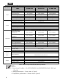
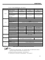
2-3-3. SE400 Specification
Electrical
Specification
Model No.
Item
SE400-112
SE400-124
SE400-148
Input
Voltage
12VDC
24VDC
48VDC
Voltage Range
10.5~16.0VDC
21.0~32.0VDC
42.0~64.0VDC
No Load Current
<1A @12VDC
<0.5A @24VDC
<0.25A @48VDC
Power Saving Mode
<0.2A @12VDC
<0.1A @24VDC
<0.05A @48VDC
Efficiency (Typ.)
88%
89%
90%
On Mode @ Saving Mode
<0.2A @12VDC
<0.1A @24VDC
<0.05A @48VDC
On Mode @ No Load Mode
<1A @12VDC
<0.5A @24VDC
<0.25A @48VDC
Output
Continuous Output Power
400 W (± 3%)
Max. Output Power (1Min.)
> 400 W~460 W (100%~115%)
Surge Power (1Sec.)
< 800 W
Frequency
50 / 60 Hz ± 0.5% (Dip Switch Selectable)
Output Voltage
100 / 110 / 115 / 120 VAC ± 5% (Dip Switch Selectable)
Short-Circuit Protection
1 Sec Shutdown
Output Waveform
Pure Sine Wave (THD < 5%@ Normal Load)
Protection
Input Over-Voltage
Protection
16.0 ± 0.3VDC
32.0 ± 0.5VDC
64.0 ± 1.0VDC
Input Under-Voltage
Protection
10.5 ± 0.3VDC
21.0 ± 0.5VDC
42.0 ± 1.0VDC
BAT. Low Shutdown
10.5 ± 0.3VDC
21.0 ± 0.5VDC
42.0 ± 1.0VDC
BAT. Low Alarm
10.5 ± 0.3VDC
21.0 ± 0.5VDC
42.0 ± 1.0VDC
BAT. Low Restart
12.5 ± 0.3VDC
25.0 ± 0.5VDC
50.0 ± 1.0VDC
BAT. High Shutdown
16.0 ± 0.3VDC
32.0 ± 0.5VDC
64.0 ± 1.0VDC
BAT. High Alarm
16.0 ± 0.3VDC
32.0 ± 0.5VDC
64.0 ± 1.0VDC
BAT. High Restart
14.5 ± 0.3VDC
29.0 ± 0.5VDC
58.0 ± 1.0VDC
Environment
Working Temp.
-20 ℃~40 ℃
Storage Temp.
-30 ℃~70 ℃
Working Humidity
10~95% RH, non-condensing
Safety &
EMC
Safety Standards
Certified UL 458
(UL only for GFCI receptacles)
----
EMC standards
Certified FCC class B
E-mark
----
Others
Dimension(WxHxD)
150 mm X 68mm X187 mm
Weight
1.256kg
Remote Control
CR-8 (optional)
Cooling
Temperature & Load Controlled cooling Fan
Table 4. SE400 for output 100/110/115/120 VAC specification
Note:
Normal load Condition:Vin =12.5V/25V/50V, Vo=100/110/115/120 VAC 80% load
(PF=1.0)
Voltage performance:Please refer to Figure 2
Temperature performance:Please refer to Figure 3

8
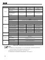
EN
Electrical
Specification
Model No.
Item
SE400-212
SE400-224
SE400-248
Input
Voltage
12VDC
24VDC
48VDC
Voltage Range
10.5~16.0VDC
21.0~32.0VDC
42.0~64.0VDC
No Load Current
<1A @12VDC
<0.5A @24VDC
<0.25A @48VDC
Power Saving Mode
<0.2A @12VDC
<0.1A @24VDC
<0.05A @48VDC
Efficiency (Typ.)
88%
89%
90%
On Mode @ Saving Mode
<0.2A @12VDC
<0.1A @24VDC
<0.05A @48VDC
On Mode @ No Load Mode
<1A @12VDC
<0.5A @24VDC
<0.25A @48VDC
Output
Continuous Output Power
400 W (± 3%)
Max. Output Power (1Min.)
> 400 W~460 W (100%~115%)
Surge Power (1Sec.)
< 800 W
Frequency
50 / 60 Hz ± 0.5% (Dip Switch Selectable)
Output Voltage
200 / 220 / 230 / 240 VAC ± 5% (Dip Switch Selectable)
Short-Circuit Protection
1 Sec Shutdown
Output Waveform
Pure Sine Wave (THD < 5%@ Normal Load)
Protection
Input Over-Voltage
Protection
16.0 ± 0.3VDC
32.0 ± 0.5VDC
64.0 ± 1.0VDC
Input Under-Voltage
Protection
10.5 ± 0.3VDC
21.0 ± 0.5VDC
42.0 ± 1.0VDC
BAT. Low Shutdown
10.5 ± 0.3VDC
21.0 ± 0.5VDC
42.0 ± 1.0VDC
BAT. Low Alarm
10.5 ± 0.3VDC
21.0 ± 0.5VDC
42.0 ± 1.0VDC
BAT. Low Restart
12.5 ± 0.3VDC
25.0 ± 0.3VDC
50.0 ± 0.3VDC
BAT. High Shutdown
16.0 ± 0.3VDC
32.0 ± 0.5VDC
64.0 ± 1.0VDC
BAT. High Alarm
16.0 ± 0.3VDC
32.0 ± 0.5VDC
64.0 ± 1.0VDC
BAT. High Restart
14.5 ± 0.3VDC
28.0 ± 0.5VDC
56.0 ± 0.5VDC
Environment
Working Temp.
-20 ℃~40 ℃
Storage Temp.
-30 ℃~70 ℃
Working Humidity
10~95% RH, non-condensing
Safety &
EMC
Safety Standards
Certified EN 62368-1
EMC standards
Certified EN55032 class B; EN 55024; EN 61000-3-2, -3-3
IEC61000-4-2, 3, 4, 5, 6, 8, 11
E-mark
Certified CISPR 25; ISO11452-2; ISO 7637-2
Others
Dimension(WxHxD)
150 mm X 68mm X187 mm
Weight
1.256kg
Remote Control
CR-8 (optional)
Cooling
Temperature & Load Controlled cooling Fan
Table 5. SE400 for output 200/220/230/240 VAC specification
Note:
Normal load Condition:Vin =12.5V/25V/50V, Vo=200/220/230/240 VAC 80% load
(PF=1.0)
Voltage performance:Please refer to Figure 2
Temperature performance:Please refer to Figure 3

9
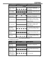
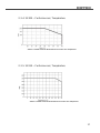
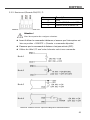
2-3-4. SE200 Voltage performance
Figure 1. SE200 temperature performance
2-3-5. SE350 Voltage performance
Figure 2. SE350 temperature performance

10
EN
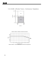
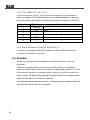
2-3-6. SE400 Voltage & temperature performance
Figure 3. SE400 voltage performance
Figure 4. SE400 temperature performance

11
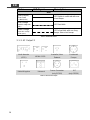
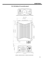
2-4. Mechanical Drawings
Figure 5. SE series mechanical drawings

12
EN
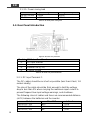
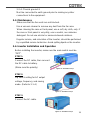
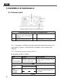
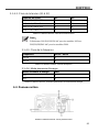
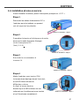
3. Installation and Maintenance
3-1. Front Panel Introduction
Figure 6. SE series front panel view
Model
SESeries Front Panel
ON / OFF / Remote Main Switch
LED Indicator
AC Output
Function Switch
Table 6. SE series front panel introduction
3-1-1. ON / OFF / Remote Main Switch
The 3-stage switch is for turning on, turning off and remote mode.
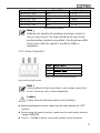
3-1-2. LED Indicator
Inverter status to display fault condition.
SE200 / SE350 LED signal
Status
LED Signal
Description
Power on
R=red, O=orange, R=red
Beep twice, LED shows red
orange green green
Green
Normal
LED lights in solid green
Saving mode
LED flashes green condition in
intermediate condition once
every 2 seconds

13
Status
LED Signal
Description
Orange
Under voltage
alarm
LED flashes orange light
slowly with 5 short beeps every
15 seconds
Over voltage
LED flashes orange light every
0.1 seconds
Red
Over
temperature
LED flashes red light quickly
twice every 1.6 seconds
O/P short circuit
LED lights red; following two
short beeps. Inverter shuts
down after two seconds and
restart 3 times.
O/P over load
LED lights red; following two
short beeps. Inverter shuts
down after 3 minutes and
restart 3 times.
Shut down
under voltage
LED flashes red light every 0.4
seconds, then inverter shuts
down.
Shut down over
voltage
LED flashes red light every 0.1
seconds, then inverter shut
down.
Fan alarm
LED flashes red light slowly
once and quickly twice every
1.6 seconds
Table 7. SE200 & SE350 LED status
SE400 LED signal
Status
LED Signal
Description
Green
Normal or
Power ON
LED lights in solid green
Orange
Over load
400W ~ 460W
(100% ~ 115%)
LED fast blink with two long
beeps
Over temp. /
Under temp.
(Heat sink temp. over
80℃ or under -20℃)
LED slow blink

14
EN
Status
LED Signal
Description
Red
Over current /
Over load
> 460W (115%)
LED lights in solid red with one
short beeps
Over voltage
(Input DC voltage over
spec.)
LED fast blink
Under voltage
(Input DC voltage
under spec.)
LED slow blink with one long
beeps &two short beeps
Table 8. SE400 LED status
3-1-3. AC Output
North America
(GFCI)
NEMA 5-15R
Australia / New
Zealand
Continental
Europe
United Kingdom
Universal
France Connector
(only SE350)
IEC
(only SE350)
Table 9. SE series AC output
La page est en cours de chargement...
La page est en cours de chargement...
La page est en cours de chargement...
La page est en cours de chargement...
La page est en cours de chargement...
La page est en cours de chargement...
La page est en cours de chargement...
La page est en cours de chargement...
La page est en cours de chargement...
La page est en cours de chargement...
La page est en cours de chargement...
La page est en cours de chargement...
La page est en cours de chargement...
La page est en cours de chargement...
La page est en cours de chargement...
La page est en cours de chargement...
La page est en cours de chargement...
La page est en cours de chargement...
La page est en cours de chargement...
La page est en cours de chargement...
La page est en cours de chargement...
La page est en cours de chargement...
La page est en cours de chargement...
La page est en cours de chargement...
La page est en cours de chargement...
La page est en cours de chargement...
La page est en cours de chargement...
La page est en cours de chargement...
La page est en cours de chargement...
La page est en cours de chargement...
La page est en cours de chargement...
La page est en cours de chargement...
La page est en cours de chargement...
La page est en cours de chargement...
La page est en cours de chargement...
La page est en cours de chargement...
La page est en cours de chargement...
La page est en cours de chargement...
La page est en cours de chargement...
La page est en cours de chargement...
La page est en cours de chargement...
-
 1
1
-
 2
2
-
 3
3
-
 4
4
-
 5
5
-
 6
6
-
 7
7
-
 8
8
-
 9
9
-
 10
10
-
 11
11
-
 12
12
-
 13
13
-
 14
14
-
 15
15
-
 16
16
-
 17
17
-
 18
18
-
 19
19
-
 20
20
-
 21
21
-
 22
22
-
 23
23
-
 24
24
-
 25
25
-
 26
26
-
 27
27
-
 28
28
-
 29
29
-
 30
30
-
 31
31
-
 32
32
-
 33
33
-
 34
34
-
 35
35
-
 36
36
-
 37
37
-
 38
38
-
 39
39
-
 40
40
-
 41
41
-
 42
42
-
 43
43
-
 44
44
-
 45
45
-
 46
46
-
 47
47
-
 48
48
-
 49
49
-
 50
50
-
 51
51
-
 52
52
-
 53
53
-
 54
54
-
 55
55
-
 56
56
-
 57
57
-
 58
58
-
 59
59
-
 60
60
-
 61
61


Cotek SE200, SE350, SE400 Manuel utilisateur
- Taper
- Manuel utilisateur
dans d''autres langues
Documents connexes
-
 Cotek SR-1600 PLUS series Manuel utilisateur
-
 Cotek SR-1600 PLUS series Manuel utilisateur
-
 Cotek SR-1600 (Shelf) Manuel utilisateur
-
 Cotek CR-6 Manuel utilisateur
-
 Cotek CR-20C Manuel utilisateur
-
 Cotek SD1500, SD2500, SD3500 Manuel utilisateur
-
 Cotek Sc Series Manuel utilisateur
-
 Cotek CX series Manuel utilisateur
-
 Cotek CX series Manuel utilisateur


Autres documents
-
Dometic SI 1500 24V Le manuel du propriétaire
-
Omega PSDIN-4100 Series Le manuel du propriétaire
-
HQ 12V-230V 2500W Manuel utilisateur
-
ZyXEL RGS100-5P Guide de démarrage rapide
-
 HQ Power PSI2000 Manuel utilisateur
-
Samlexpower SAM-100-12 Le manuel du propriétaire
-
Trendnet TI-SG104 Quick Installation Guide
-
Samlexpower SAM-800-12 Le manuel du propriétaire
-
Wagan Elite™ 700W PRO Manuel utilisateur
-
