Cotek CX series Manuel utilisateur
- Catégorie
- Chargeurs de batterie
- Taper
- Manuel utilisateur

CX Series User’s Manual
Manuel utilisateur série CX
Advanced Converter / Charger
Chargeurs de batterie multiphases


Legal Provisions
Copyrights 2017 COTEK Electronic IND. CO. All Rights Reserved.
Any part of this document may not be reproduced in any form for any purpose without the prior
written permission of COTEK Electronic IND. CO. For the conditions of the permission to use
this manual for publication, contact COTEK Electronic IND. CO., LTD. In all related COTEK
product activities, Neither COTEK Electronic IND. CO., LTD. nor its distributors or dealers be
liable to anyone for indirect, incidental, or consequential damages under any circumstances.
Specifications are subject to change without notice. Every attempt has been made to make this
document complete, accurate and up-to-date. COTEK Electronic IND. CO., LTD reserve the
right to make changes without notice and shall not be responsible for any damages, including
indirect, incidental or consequential damages, caused by reliance on the material presented,
including, but not limited to, omissions, typographical errors, arithmetical errors or listing errors
in the content material. All trademarks are recognized even if these are not marked separately.
Missing designations do not mean that a product or brand is not a registered trademark.
Dispositions légales
Copyrights 2017 COTEK Electronic IND. CO. tous droits réservés.
Aucune partie de ce document ne peut être reproduite, quelle qu’en soit la manière et quel
qu’en soit le but, sans autorisation préalable écrite de COTEK Electronic IND. CO. Pour obtenir
l’autorisation de publier ce manuel, adressez-vous directement à COTEK Electronic IND. CO.,
LTD. Pour l’ensemble des activités COTEK, ni COTEK Electronic IND. CO., LTD. ni ses
distributeurs ou revendeurs ne sauraient être tenus responsables, d’aucune manière, de tout
dommage direct, indirect ou accessoire. Les caractéristiques peuvent être modifiées sans
notification préalable. Tout a été mis en œuvre pour que ce document soit complet, précis et à
jour. COTEK Electronic IND. CO., LTD. se réserve le droit d’apporter des modifications sans
notification et ne saurait être tenu responsable de tout dommage direct, indirect ou accessoire
causé par l’utilisation de ce contenu, y compris mais non limité à des omissions, des coquilles,
des erreurs de calcul ou de description. Toutes les marques sont protégées même sans
indication spécifique. L’absence de logo ne signifie pas que le produit ou la marque ne sont pas
protégés.


EN
Table of Content
1. Important Safety Information 1
1-1. General Safety Precautions 1
1-2. Battery Precautions 2
2. Features 3
2-1. Battery Charging Curve 4
2-2. Specification 6
2-3. Mechanical Drawings 9
3. Product Description 13
3-1. Configurations 13
3-2. S1 Setting 14
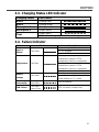
3-3. Charging Status LED Indicator 15
3-4. Failure Indicator 15
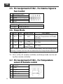
3-5. Pin Assignment of CN2 – For Alarms Signal & Fan Control 16
3-6. Sleep Mode 16
3-7. Pin Assignment of CN3 – For Temperature sensor & Remote control 16
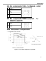
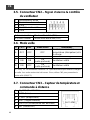
3-8. Pin Assignment of CN4 – For Remote control 17
3-9. Pin Assignment of ESB Connectors – For CX1215/1225/1235 17
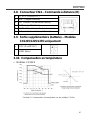
3-10. Temperature Compensation 17
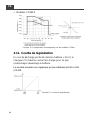
3-11. Rescue Battery Curve 18
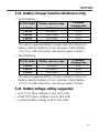
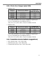
3-12. Battery Charger Selection (Reference only) 19
3-13. Battery Voltage setting suggestion 19
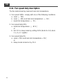
3-14. Fan speed duty description 20


1
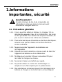
1. Important Safety
Information
Warning!
Before installing or using CX series power converter,
you need to read following safety information carefully.
1-1. General Safety Precautions
1-1-1. For indoor use, do not expose CX-Series Battery Charger
to water, mist, snow, or dust. To reduce the risk of fire, do
not cover or obstruct the ventilation enclosure.
1-1-2. To avoid the risk of fire and electric shocks, make sure
that existing wiring is in good electrical condition and not
undersized.
1-1-3. Do not charge non-rechargeable batteries.
1-1-4. Disconnect the AC Grid before making or breaking the
connections to the battery.
1-1-5. Only the AC cord with IEC socket is allowed to plug to the
battery charger.
1-1-6. Never charge a frozen battery.
1-1-7. If the AC cord is damaged do not attempt to use. It must
be replaced or repaired by a qualified person.
1-1-8. Corrosive substances may escape from the battery
during charging and damage delicate surfaces. Please
store and charge in a suitable area.

2
EN
1-2. Battery Precautions
1-2-1. If battery acid contacts your skin or clothing, wash it out
with soap and water immediately.
1-2-2. If battery acid contacts your eyes, wash it out with cold
running water for at least 20 minutes and get medical
attention immediately.
1-2-3. Never smoke or make a spark or flame in the vicinity of
the battery.
1-2-4. Do not drop metals on the battery.
The resulting sparks or short-circuits on the battery or
other electrical parts may cause an explosion.
1-2-5. Remove personal metal items such as rings, bracelets,
necklaces, and watches when operating with lead-acid
batteries. It may cause short circuit and very high
temperature, which can melt metal items.

3
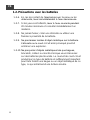
2. Features
Universal AC input with active PFC
Compatible with Lead Acid, Li-ion, Gel and AGM batteries
Support remote controller CR-1 as optional accessory
Voltage / temperature compensation
2 stage fan speed control (Sleep mode)
Output power OK signal
Output alarm signal
High efficiency and high reliability
Built-in battery rescue function
Built-in Extra Second Battery (ESB) output function
Protection Short Circuit / Over Voltage / Over Temperature /
Brown-out Protection
Withstand 2G vibration test

4
EN
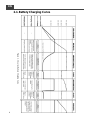
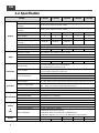
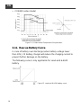
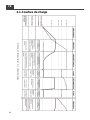
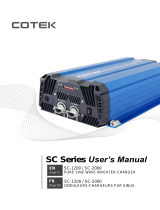
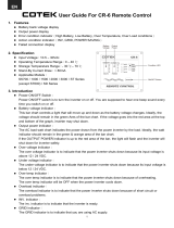
2-1. Battery Charging Curve
Figure
1. CX series
Battery Charging Curve

5
2-1-1. Bulk Stage (Constant Current)
At the beginning of the charging process, the flat battery is
charged at constant current (maximum charge current) until the
battery voltage reaches the set charging voltage (Refer to 3-2
charging mode setting).
2-1-2. Absorption Stage (Constant Voltage)
The absorption charging duration will depend on the battery
status.
Before moving to absorption stage, charger will wait for two
minutes then charging at constant voltage until the battery is fully
charged.
Once the battery is fully charged or the charging current is below
6.25% of the rated charging current for 15 minutes, then the
absorption stage ends.
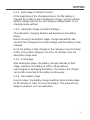
2-1-3. Float Stage
After absorption stage, the battery charger switches to float
stage, maintains the battery at 100% charge without
overcharging or damaging the battery. This means the charger
can be left connected to the battery continuously.
2-1-4. Recondition stage
Every 14 days, the battery charger switches back to Bulk stage
for 85 minutes in order to revive the battery. This prevents any
fatigue symptoms such as sulphation.

6
EN
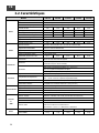
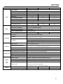
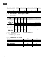
2-2. Specification
Model
CX1215
CX1225
CX1235
CX1250
CX1280
Output
Battery Type
Lead Acid / Li-ion / Gel / AGM
Standard Boost Charge
Voltage
14.4V / 14.7V (Select by S1 DIP switch)
Standard Float Charge
Voltage
13.8V / 13.5V (Select by S1 DIP switch)
Main Rated Current
15A
25A
35A
50A
80A
Main Output
1
2
2
3
3
ESB Output
1
1
1
--
--
ESB Output Voltage /
Current
13.8V/2A
13.8V/2A
13.8V/2A
--
--
Battery Charging Mode
3-stage charging capability IUOU
Isolation Type
Use active power MOSFET on each output terminal
Single Output Current Limit
15A
25A
35A
40A
40A
Input
Nominal Voltage
100~240VAC (100~120VAC only for UL458)
Voltage Range
90~264VAC (90-132VAC only for UL458) (Refer to 2-2-2 de-rating curve)
Frequency Range
47~63Hz
Power Factor (Typ.)
PF > 0.92 at full load
Efficiency (Typ.) at 230Vac
87%
87%
87%
87%
87%
Protection
Short Circuit
Current is reduced to < 1A continued 30sec.,
will operate 30 seconds then turn off
Over Voltage
17.5V ±1%, protection type: shut down output
(recovery after resetting AC power ON)
Over Temperature
Charger Over Temperature 100 ±5°C detected by heat sink
52±5°C (Optional temperature sensor)
Auto recovery after heat sink temperature goes down to 50±5°C
Function
Alarm Signal
NC. / NO. Relay contact output (Please reference Alarms signal & Fan control)
Temp. Compensation
12V:-10mv / 0.5°C with COTEK temperature sensor
24V:-20mv / 0.5°C with COTEK temperature sensor
Sleep Mode
By Remote Controller and S1-4 DIP switch (Please refer to section 3-2)
Remote Controller
Support COTEK Remote Controller CR-1 (Refer to section 3-6 and 3-7)
Environment
Working Temperature
-20~40°C (Refer to 2-2-2 de-rating curve)
Working Humidity
20~90% RH non-condensing
Temperature Coefficient
±0.03% (0~50°C)
Vibration
10~500Hz, 2G 10min. / 1cycle period for 60min. each along X, Y, Z axes.
Safety
&
EMC
Safety Standards
Certified EN 60335-1, EN 60335-2-29, UL458 (only for CX1235/1250/1280)
Withstand Voltage
I/P-O/P: 4242VDC, I/P-FG: 1768VDC, O/P-FG: 707VDC
Isolation Resistance
I/P-O/P: 100M Ohms / 500VDC
EMC Standards
Certified EN 61204-3; EN 55014-1
Certified EN 61000-3-2; EN 61000-3-3; EN 61000-6-3
Certified IEC 61000-4-2, 3, 4, 5, 6, 8, 11; EN 61000-6-1; EN 55014-2
Others
Dimension (WxHxD)
183x72x243 mm
183x72x263 mm
213x77x272 mm
213x77x312 mm
Packing
1.6 kg
1.7 kg
1.9 kg
3.1 kg
4.0 kg

7
Model
CX2415
CX2425
CX2440
Output
Battery Type
Lead Acid / Li-ion / Gel / AGM
Standard Boost Charge
Voltage
28.8V / 29.4V (Select by S1 DIP switch )
Standard Float Charge
Voltage
27.6V / 27V (Select by S1 DIP switch)
Main Rated Current
12.5A
25A
40A
Main Output
2
3
3
ESB Output
--
--
--
ESB Output Voltage /
Current
--
--
--
Battery Charging Mode
3-stage charging capability IUOU
Isolation Type
Use active power MOSFET on each output terminal
Single Output Current Limit
12.5A
25A
40A
Input
Nominal Voltage
100~240VAC (100~120VAC only for UL458)
Voltage Range
90~264VAC (90-132VAC only for UL458) (Refer to 2-2-2 de-rating curve)
Frequency Range
47~63Hz
Power Factor (Typ.)
PF > 0.92 at full load
Efficiency (Typ.) at 230Vac
90%
90%
90%
Protection
Short Circuit
Current is reduced to < 1A continued 30sec.,
will operate 30 seconds then turn off
Over Voltage
35V ±1%, protection type: shut down output
(recovery after resetting AC power ON)
Over Temperature
Charger Over Temperature 100 ±5°C detected by heat sink
52±5°C (Optional temperature sensor)
Auto recovery after heat sink temperature goes down to 50±5°C
Function
Alarm Signal
NC. / NO. Relay contact output (Please reference Alarms signal & Fan control)
Temp. Compensation
12V:-10mv / 0.5°C with COTEK temperature sensor
24V:-20mv / 0.5°C with COTEK temperature sensor
Sleep Mode
By Remote Controller and S1-4 DIP switch (Please refer to section 3-2)
Remote Controller
Support COTEK Remote Controller CR-1 (Refer to section 3-6 and 3-7)
Environment
Working Temperature
-20~40°C (Refer to 2-2-2 de-rating curve)
Working Humidity
20~90% RH non-condensing
Temperature Coefficient
±0.03% (0~50°C)
Vibration
10~500Hz, 2G 10min. / 1cycle period for 60min. each along X, Y, Z axes.
Safety
&
EMC
Safety Standards
Certified EN 60335-1, EN 60335-2-29, UL458 (only for CX2425/2440)
Withstand Voltage
I/P-O/P: 4242VDC, I/P-FG: 1768VDC, O/P-FG: 707VDC
Isolation Resistance
I/P-O/P: 100M Ohms / 500VDC
EMC Standards
Certified EN 61204-3; EN 55014-1
Certified EN 61000-3-2; EN 61000-3-3; EN 61000-6-3
Certified IEC 61000-4-2, 3, 4, 5, 6, 8, 11; EN 61000-6-1; EN 55014-2
Others
Dimension (WxHxD)
183x72x243 mm
213x77x272 mm
213x77x312 mm
Packing
1.6 kg
2.9 kg
3.9 kg

8
EN
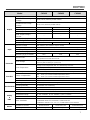
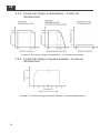
2-2-1. Charging Current vs. Temperature De-rating Curve
Figure 2. Charging current vs. temperature de-rating curve
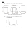
2-2-2. Charging Current vs. Input Voltage Temperature
De-rating Curve
Figure 3. Charging current vs. Input voltage temperature de-rating curve

9
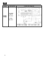
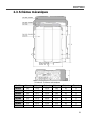
2-3. Mechanical Drawings
Figure 4. Mechanical Drawings
Model
A (mm)
B (mm)
C (mm)
D (mm)
E (mm)
F (mm)
CX1215
243
54.2
135.0
183
6.5
72
CX1225
243
54.2
135.0
183
6.5
72
CX1235
263
56.7
150.0
183
6.5
72
CX1250
272
60.2
152.0
213
6.5
77
CX1280
312
65.2
182.0
213
6.5
77
CX2415
243
54.2
135.0
183
6.5
72
CX2425
272
60.2
152.0
213
6.5
77
CX2440
312
65.2
182.0
213
6.5
77

10
EN
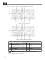
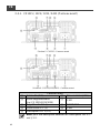
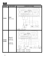
2-3-1. CX1215 / 1225 / 1235 / 2415 (Front Panel)
Figure 5. CX1215 front panel
Figure 6. CX1225/1235/2415 front panel
Front panel
①
AC Inlet (IEC)
⑥
Status LED
②
ESB connector
(only CX 1215/1225/1235)
⑦
CN2
③
DC output -
⑧
TEMP/CN3
④
DC output +
⑨
CN4
⑤
Dip Switch 1 (S1)
Note: For detail description on item 5 (Dip Switch S1),
please refer to section 3-2

11
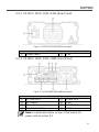
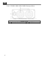
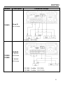
2-3-2. CX1215 / 1225 / 1235 / 2415 (Rear Panel)
Figure 7. CX1215/1225/1235/2415 rear panel
Rear panel
①
Power Switch
②
Fan
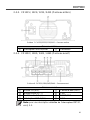
2-3-3. CX1250 / 1280 / 2425 / 2440 (Front Panel)
Figure 8. CX1250/1280/2425/2440 front panel
Front panel
①
AC Inlet (IEC)
⑤
Status LED
②
DC output -
⑥
CN2
③
DC output +
⑦
TEMP/CN3
④
Dip Switch 1 (S1)
⑧
CN4
Note: For detail description on item 4 (Dip Switch S1),
please refer to section 3-2

12
EN
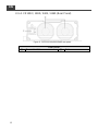
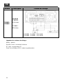
2-3-4. CX1250 / 1280 / 2425 / 2440 (Rear Panel)
Figure 9. CX1250/1280/2425/2440 rear panel
Rear panel
①
Power Switch
②
Fan

13
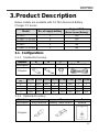
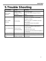
3. Product Description
Below models are available with COTEK Advanced Battery
Charger CX Series:
Model
No. of supply battery
Support ESB
(Extra Second Battery)
CX1215
1
Yes
CX1225 / CX1235
2
Yes
CX1250 / CX1280
3
No
CX2415
2
No
CX2425 / CX2440
3
No
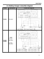
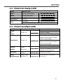
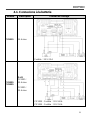
3-1. Configurations
3-1-1. Standard Accessory
Number
A
B
C
D
Description
Copper Bus
Screw
AC Power Cable
Diagram
Quantity
per
CX 1215
CX 1225
CX 1235
CX 1250
CX 1280
CX 2415
CX 2425
CX 2440
A
x
1pcs
1pcs
x
x
1pcs
x
x
B
x
x
x
1pcs
1pcs
x
1pcs
1pcs
C
x
2pcs
2pcs
3pcs
3pcs
2pcs
3pcs
3pcs
D
1pcs
1pcs
1pcs
1pcs
1pcs
1pcs
1pcs
1pcs
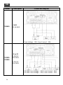
3-1-2. Optional Accessory
Number
A
B
C
Description
Ring Terminal
Battery Temp Sensor
Remote
Diagram

14
EN
Number
CX 1215
CX 1225
CX 1235
CX 1250
CX 1280
CX 2415
CX 2425
CX 2440
A
2pcs
3pcs
3pcs
5pcs
5pcs
3pcs
5pcs
5pcs
B
1pcs
1pcs
1pcs
1pcs
1pcs
1pcs
1pcs
1pcs
C
1pcs
1pcs
1pcs
1pcs
1pcs
1pcs
1pcs
1pcs
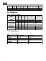
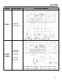
3-2. S1 Setting
3-2-1. Dip switch setting
Status
1
2
3
4
12V / 24V
CC/CV
12V / 24V
Float
CC turn to CV
voltage
ON
X
OFF
X
14.4V / 28.8V
---
OFF
X
OFF
X
14.7V / 29.4V
---
Float voltage
X
ON
OFF
X
---
13.5V / 27.0V
X
OFF
OFF
X
---
13.8V / 27.6V
Power Mode
(Current limit
output voltage)
OFF
OFF
ON
X
13.2V / 26.4V
OFF
ON
ON
X
13.8V / 27.6V
ON
OFF
ON
X
14.4V / 28.8V
Remote
ON
ON
ON
X
---
---
Sleep Mode
X
X
X
ON
---
---
X
X
X
OFF
---
---
X: Not Applicable
---: By Default setting
3-2-2. Default setting
Model
12V Series
24V Series
CC/CV
14.4V
28.8V
Float
13.8V
27.6V
Power Mode
Off
Off
Remote
Off
Off
Fan
Full Speed
Full Speed
La page charge ...
La page charge ...
La page charge ...
La page charge ...
La page charge ...
La page charge ...
La page charge ...
La page charge ...
La page charge ...
La page charge ...
La page charge ...
La page charge ...
La page charge ...
La page charge ...
La page charge ...
La page charge ...
La page charge ...
La page charge ...
La page charge ...
La page charge ...
La page charge ...
La page charge ...
La page charge ...
La page charge ...
La page charge ...
La page charge ...
La page charge ...
La page charge ...
La page charge ...
La page charge ...
La page charge ...
La page charge ...
La page charge ...
La page charge ...
La page charge ...
La page charge ...
La page charge ...
La page charge ...
La page charge ...
La page charge ...
La page charge ...
La page charge ...
La page charge ...
La page charge ...
La page charge ...
-
 1
1
-
 2
2
-
 3
3
-
 4
4
-
 5
5
-
 6
6
-
 7
7
-
 8
8
-
 9
9
-
 10
10
-
 11
11
-
 12
12
-
 13
13
-
 14
14
-
 15
15
-
 16
16
-
 17
17
-
 18
18
-
 19
19
-
 20
20
-
 21
21
-
 22
22
-
 23
23
-
 24
24
-
 25
25
-
 26
26
-
 27
27
-
 28
28
-
 29
29
-
 30
30
-
 31
31
-
 32
32
-
 33
33
-
 34
34
-
 35
35
-
 36
36
-
 37
37
-
 38
38
-
 39
39
-
 40
40
-
 41
41
-
 42
42
-
 43
43
-
 44
44
-
 45
45
-
 46
46
-
 47
47
-
 48
48
-
 49
49
-
 50
50
-
 51
51
-
 52
52
-
 53
53
-
 54
54
-
 55
55
-
 56
56
-
 57
57
-
 58
58
-
 59
59
-
 60
60
-
 61
61
-
 62
62
-
 63
63
-
 64
64
-
 65
65


Cotek CX series Manuel utilisateur
- Catégorie
- Chargeurs de batterie
- Taper
- Manuel utilisateur
dans d''autres langues
- English: Cotek CX series User manual
Documents connexes
Autres documents
-
Samlexpower SEC-2440A Le manuel du propriétaire
-
Vetus Operational and battery charger Guide d'installation
-
-
-
Dometic Energy and Lighting Perfectcharge Battery Charger Manuel utilisateur
-
-
CARLO GAVAZZI SPM 5BC Guide d'installation
-
CARLO GAVAZZI SPP112201 Guide d'installation