La page est en cours de chargement...

1
User Guide For CR-6 Remote Control
1. Features
Battery bank voltage display
Output power display
Error condition indicator(High Battery, Low Battery, Over Temperature, Over Load conditions)
Action condition indicator(INV, GRID, POWER SAVING)
Failed connection display
2. Specification
Input Voltage : 10.5 – 30Vdc
Operating Temperature Range : 0 – 40 ℃
Storage Temperature Range : - 30 ℃– 70 ℃
Stand-By Current Draw : < 80mA
Applicable Models :
SK700 / 1000 / 1500 / 2000 / 3000
/ ST Series
(except ST600) / SD Series
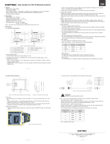
3. Introduction
Power ON/OFF Switch:
Power ON/OFF switch is to turn the inverter on or off. You are supposed to hear one beep sound every
time you switch on or off.
Battery voltage indicator:
This bar chart controls a light that will move up and down as the battery voltage changes. Ideally, the
voltage should remain in the green Ares of the bar chart. If the voltage goes into the red area at the top
and bottom of the graph, inverter may shut down.
Output power indicator:
T
he AC load watt chart indicates the power drawn from the power inverter by the load. Ideally, the watt
indicator should remain in the green & orange area of the bar chart.
If the OUTPUT POWER indicator is up to the red area of the bar, the light will flash and the inverter will
shut down for inverter safety.
Over voltage indicator:
The over voltage indicator is to indicate that the power inverter shuts down because its input voltage is
above 12 / 24 VDC.
Under voltage indicator:
The
under voltage indicator is to indicate that the power inverter shuts down because its input voltage is
below 12 / 24 VDC.
Over temp indicator:
The over temp indicator is to indicate that the power inverter shuts down because of overheating.
The over temp indicator will be OFF when the power inverter cools down.
Overload indicator:
The overload indicator is to indicate that the power inverter shuts down because of short circuit or
overload problems.
INV. indicator:
The inv. indicator is to indicate
that the inverter is ready.
GRID indicator:
The GRID indicator is to indicate that you are using AC supply.
EN
Battery
Voltage
Output
Power
Condition LED
ON/OFF Button

2
PWR.SAV. Indicator:Power saving functions are described below:
LED
Meaning
Inverter Output
Solid
Ready
ON
Flashing
Active
OFF
Off
Inactive
The wire JP1 is placed inside the remote controller and it is to present either Return Override Function
or Ignition lockout function.
* JP1 jumper “Short” – Return Override Function
* JP1 jumper “Open” – Ignition Lockout Function
Please note that the default mode is Open.
The connector connected to AUX wire must go with 12V / 0.5A fuse by proper sizes.
Connect the wire RJ – 11 to the remote port in front of the panel.
* Ignition Lockout function – The ignition lockout function is to
turn the Inverter OFF when the auxiliary
input wiring is connected to the ACC, and 12 Volts is applied.
* Return Override Function – The Return Override Function is to turn the inverter ON when the auxiliary
input wiring is connected to the reverse gear Shift, and 12 Volts is applied.
Installation Procedure:
1. Refer to the drawing for hole and cutout
dimensions.
2. Use the cable between CR6 remote and the
inverter.
3. Switch the inverter to REMO positi
on.
4. Drawings of CR6 Remote Control Cables
WARNING!
DO NOT use standard telephone cable.
No.33, Sec. 2, Renhe Rd., Daxi Dist., Taoyuan City 33548, Taiwan
Phone:+886-3-3891999 FAX:+886-3-3802333
http:// www.cotek.com.tw
2016.12._A1
PHONE
JACK
120.0 [4.72]
110.0 [4.33]
84.0 [3.31]
95.0 [3.74]
JP1
AUX
A
6
1
B
6
1
9.6±0.2
9.6±0.2
12.4±0.3
6.5±0.2
14.6±0.3
3.1±0.2
12.4±0.3
6.5±0.2
14.6±0.3
3.1±0.2
CONDUCTOR
INSULATION
JACKET
A
6
5
4
3
2
1
COLOR
YELLOW
NC
GREEN
NC
BLACK
RED
B
6
5
4
3
2
1

3
Manuel utilisateur
Panneau de commande à distance CR-6
1. Présentation
Affichage de la tension batterie.
Affichage de la puissance de sortie.
Affichage des défauts (tension batterie haute, tension batterie basse, surchauffe, surcharge).
Témoins mode de fonctionnement (INV, GRID, POWER SAVING).
Notification en cas d’erreur de connexion.
2. Caractéristiques
Plages de tension admissibles (alimentation) :
10,5 à 30 V CC
Plages de températures admissibles
(fonctionnement) : 0 à 40°C
Plages de températures admissibles (stoc
kage) :
-30°C à +70°C
Consommation à vide : <80mA
Compatibilité :
o Onduleurs série SK 700 / 1000 / 1500 / 2000 /
3000
o Onduleurs série ST (Sauf ST 600)
o Onduleurs série SD
3. Introduction
Interrupteur ON/OFF : permet de mettre en marche / d’arrêter l’onduleur. Emet un bip à chaque
manipulation.
Affichage de la tension batterie (barres) : un témoin lumineux indique le niveau de la batterie.
Idéalement la tension doit rester en zone verte. Si les barres rouges sont allumées (en zone basse ou
haute), l’onduleur peut s’arrêter.
Affichage de la puissance de sortie CA (barres) : un témoin lumineux indique le niveau de charge
exprimé en Watts. Idéalement il doit rester en zone verte & orange. Si une barre est allumée en haut,
elle va clignoter puis l’onduleur sera coupé pour éviter qu’il ne soit endommagé.
Témoin tension batterie haute (OVP) : ce témoin indique que l’onduleur a été coupé en raison d’une
sur-tension.
Témoin tension batterie basse (UVP) : ce témoin indique que l’onduleur a été coupé en raison d’une
sous-tension.
Témoin de surchauffe (OTP) : ce témoin indique que l’onduleur a été coupé en raison d’une surchauffe.
Le témoin s’éteint lorsque l’onduleur a refroidi.
Témoin de surcharge (OLP) : ce témoin indique que l’onduleur a été coupé en raison d’un court-circuit
ou de charges dépassant ses limites fonctionnelles.
Témoin INV (onduleur) : ce témoin indique que l’appareil est en mode onduleur.
Témoin GRID (réseau) : ce témoin indique que l’onduleur est branché sur une alimentation courant
alternatif.
Témoin PWR.SAV (mode économie d’énergie) :
Allumé
Prêt
Sortie ON
Flashs
Actif
Sortie OFF
Éteint
Inactif
Cavalier – JP1
Il permet de sélectionner les fonctions Marche/Arrêt de l’onduleur.
Sans le cavalier : fonction « Ignition Lockout » (arrêt de l'onduleur lorsque le moteur tourne).
Avec le cavalier : fonction « ROF » (marche de l'onduleur lorsque la marche arrière est engagée).
Le panneau est livré avec JP1 ouvert.
FR
Tension
Batterie
Puissance
de sortie
Etat de l’onduleur
Interrupteur Marche/Arrêt

4
La borne AUX doit être protégée par un fusible 12 V / 0,5 A.
Utiliser le câble RJ-11 pour raccorder la borne REMOTE de l’onduleur au panneau de commande à
distance.
Fonction ROF (Return Override Function)
La présence d’un signal +12V permanent sur le contact auxiliaire déclenche la mise en marche de
l’onduleur.
Ce signal peut être envoyé depuis le contact de marche arrière sur la boîte de vitesses.
Fonction Ignition Lockout
La présence d’un signal +12V permanent sur le contact auxiliaire déclenche l’arrêt de l’onduleur.
Ce signal peut être envoyé depuis la position Accessoires du contacte
ur à clé de démarrage.
4. Installation
(1) Se reporter au schéma de cotes ci-dessous pour effectuer la découpe de montage.
(2) Utiliser le câble RJ-11 pour raccorder l’onduleur au panneau de commande à distance CR-6.
(3) Placer l’interrupteur sur l’onduleur en position « REMO » (=REMOTE = commande à distance).
5. Cotes
6. Câble RJ-11
ATTENTION!
Ne pas utiliser du câble téléphonique standard pour raccorder l’onduleur
au panneau de commande à distance.
No.33, Sec. 2, Renhe Rd., Daxi Dist., Taoyuan City 33548, Taiwan
Phone:+886-3-3891999 FAX:+886-3-3802333
http:// www.cotek.com.tw
2016.12._A1
PHONE
JACK
120.0 [4.72]
110.0 [4.33]
84.0 [3.31]
95.0 [3.74]
JP1
AUX
A
6
1
B
6
1
9.6±0.2
9.6±0.2
12.4±0.3
6.5±0.2
14.6±0.3
3.1±0.2
12.4±0.3
6.5±0.2
14.6±0.3
3.1±0.2
Conducteur
Isolation
Gaine
A
6
5
4
3
2
1
Couleur fil
Jaune
NC
Vert
NC
Noir
Rouge
B
6
5
4
3
2
1
1/4