
VACUUM PUMP SERIES
VP & VPC SINGLE - DUAL STAGE VACUUM PUMPS
OPERATION MANUAL

GENERAL INFORMATION
2
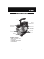
Thank you for purchasing the CPS
®
Pro-Set
®
VP vacuum pump series. Our vacuum
pumps are specifically designed for the air-conditioning and refrigeration service
industry. The VP and VPC series both utilize an electrical motor and oil filled rotary
vacuum pump cartridge construction.
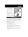
Features:
• Equipped with our exclusive oil mist free exhaust port
• VP series dual stage models are equipped with gas ballast valve
• The dual voltage models can be quickly converted to 115 or 230 volt operation
• Sure-Grip handle, ergonomically designed for superior comfort and portability
• Solid rubber base provides extreme shock resistance
• Air cooled motor design allows for operation under high temperature conditions
• The VP & VPC series excel in vacuum performance, rated 10-15 microns (Dual
Stage) and 50-100 microns (Single Stage)
• All vacuum pumps allow for multiple connections, therefore giving full operational
preference
• Accessible oil drain port & sight glass make both oil maintenance and accuracy easy
To help you get a good start, please continue to carefully read the balance of this manu-
al. This manual contains important information on the proper procedures for operating
this equipment. Please pay close attention to the: Safety Information, Warnings, and
Cautions provided throughout this manual.
ALWAYS REMEMBER “ SAFETY FIRST ”
Table of Contents
Introduction
General Information 2-5
Introduction 2
General Safety Instructions 3
Specifications
4-5
Operation 6-10
VP & VPC Series Parts 6-7
Initial Preparation 8
Vacuum Pump Operation 8-9
Routine Maintenance 9
Troubleshooting Chart 10
Warranty 11

GENERAL INFORMATION
3
General Safety Instructions
ONLY QUALIFIED SERVICE PERSONNEL SHOULD OPERATE THIS UNIT. SOME COUN-
TRIES MAY REQUIRE THE USER TO BE LICENSED. PLEASE CHECK WITH YOUR LOCAL
GOVERNMENT AGENCY.
CAUTION: THIS EQUIPMENT IS INTENDED FOR USE OF FINAL EVACUATION OF A RE-
FRIGERANT SYSTEM. THE EVACUATION OF MATERIALS ABOVE 5 PSIG
MAY CONTAMINATE OR DAMAGE THE VACUUM PUMP.
CAUTION: DO NOT RUN THIS EQUIPMENT WITH LOW OR NO OIL. RUNNING
THIS EQUIPMENT WITH NO LUBRICATION WILL CAUSE PREMATURE FAILURE.
DANGER - Avoid breathing refrigerant
vapors and lubricant vapor or mist. Breath-
ing high concentration levels may cause
heart arrhythmia, loss of consciousness,
or even cause suffocation.
DANGER - ELECTRICAL SHOCK
HAZARD - Always disconnect power
source when servicing this equipment.
WARNING - Do not operate the vacuum
pump on systems under pressure. Dam-
age to the pump may occur.
CAUTION - All hoses may contain liquid
refrigerant under pressure. Contact with
refrigerant may cause frostbite or other
related injuries. Wear proper personal pro-
tective equipment such as safety goggles
and gloves. When disconnecting any hose,
please use extreme caution.
CAUTION - Avoid breathing refriger-
ant vapors and/lubricant mist. Exposure
may irritate eyes, nose, throat and skin.
Please read the manufacturers Mate-
rial Safety Data Sheet for further safety
information on refrigerants and lubricants.
CAUTION - To reduce the risk of fire, avoid
the use of extension cords thinner than
NO. 14 awg. (2,5mm
2
) to prevent the over-
heating of this cord please keep length to
a minimum.
CAUTION - Do not use this equipment in
the vicinity of spilled or open containers of
gasoline or other flammable substances.
Make certain that all safety devices are
functioning property before operating the
equipment.

GENERAL INFORMATION
4
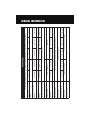
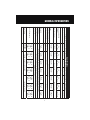
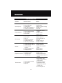
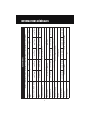
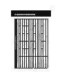
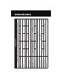
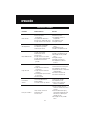
Specifications
* “Blank” = Dual voltage (110-120 / 220 50/60Hz E = 220-240V 50/60Hz J = 100V 50/60Hz U = 115V 50/60Hz
Model Number VPC2S* VPC4S* VP2S* VP4S* VP6S*
Stages 1 1
Motor Size (HP) RPM @
50/60Hz
1/5
2880 / 3440
1/4
2880 / 3440
1/4
1440 / 1720
1/3
2880 / 3440
1/2
2880 / 3440
Dimensions (Inches) 9.1 x 4.5 x 8.0 11.3 x 4.5 x 8.0 12.2 x 5 x 9.6 13.1 x 5.5 x 10
Weight 9.3 lb / 4.2 kg 11.0 lb / 5 kg 13.7 lb / 6.2 kg 15.0 lb / 6.8 kg 18.3 lb / 8.3 kg
Operating Temperature Range 0˚C (32˚F) to 52˚C (125˚F)
Power Source Available* U, E, J Dual
Ultimate Vacuum as low as 100 Microns 50 Microns
Oil Capacity 9 oz / 250 ml 10 oz / 300 ml 16 oz / 470 ml 16 oz / 470 ml 19 oz / 550 ml
Construction Heavy Gauge Aluminum Chasis with hard rubber base and rubber lined steel handle
Overload Protection Motor Thermally Protected, Dual Voltage units have extra IEC fuse
Control System ON-OFF power switch
Free Air Displacement
2 CFM @ 60Hz
48 l/m @ 50Hz
4 CFM @ 60Hz
96 l/m @ 50Hz
2 CFM @ 60Hz
48 l/m @ 50Hz
4 CFM @ 60Hz
96 l/m @ 50Hz
6 CFM @ 60Hz
144 l/m @ 50Hz
Intake Fittings 1/4 SAE and 1/2 ACME 1/4 SAE, 3/8 SAE, and 1/2 ACME
Gas Ballast Valve No

GENERAL INFORMATION
5
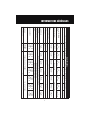
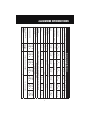
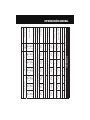
Specifications
* “Blank” = Dual voltage (110-120 / 220 50/60Hz E = 220-240V 50/60Hz J = 100V 50/60Hz U = 115V 50/60Hz
Mode Number VPC2D* VP2D* VP4D* VP6D* VP8D* VP10D* VP12D*
Stages 2
Motor Size (HP) RPM
@ 50/60Hz
1/4
2880 / 3440
1/3
1440 / 1720
1/2
2880 / 3440
1/2
2880 / 3440
2/3
2880 / 3440
3/4
2880 / 3440
1
2880 / 3440
Dimensions (Inches)
11.3 x 4.5
x 8.0
12.2 x 5 x
9.6
13.1 x 5.5 x 10 14.9 x 5.7 x 10.6
Weight
12.1 lb /
5.5 kg
17.7 lb /
8.0 kg
22.1 lb /
10.0 kg
22.5 lb /
10.2kg
29.8 lb /
13.5kg
30.3 lb /
13.7kg
30.9 lb /
14.0kg
Operating Temperature Range 0˚C (32˚F) to 52˚C (125˚F)
Power Source Available* E, U, J Dual, E, J Dual, J
Ultimate Vacuum 15 Microns 10 Microns
Oil Capacity
9 oz /
250ml
11.5 oz /
330ml
15.5 oz /
450ml
14 oz /
400 ml
29 oz/
860 ml
28 oz /
830 ml
27 oz /
800 ml
Construction
Heavy Gauge Aluminum Chasis with hard rubber base and rubber lined steel handle
Overload Protection Motor Thermally Protected, Dual Voltage units have extra IEC fuse
Control System
ON-OFF power switch
Free Air Displacement
2 CFM @
60Hz
48 l/m @
50Hz
2 CFM @
60Hz
48 l/m @
50Hz
4 CFM @
60Hz
96 l/m @
50Hz
6 CFM @
60Hz
144 l/m @
50Hz
8 CFM @
60Hz
192 l/m @
50Hz
10 CFM @
60Hz
240 l/m @
50Hz
12 CFM @
60Hz
288 l/m @
50Hz
Intake Fittings
1/4 SAE &
1/2 ACME
1/4 SAE, 3/8 SAE, and 1/2 ACME 1/4, 3/8 and 1/2 SAE
Gas Ballast Valve No Yes

OPERATION
6
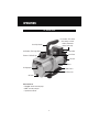
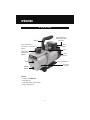
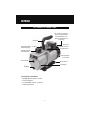
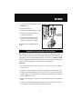
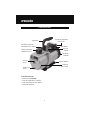
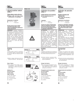
VP Series Parts
Sure Grip Handle
Gas Ballast (Two Stage Only)
Rubber Base
Motor
Oil Reservoir
Fan Inlet
Electrical Box
Exhaust / Oil Refill Cap
Oil Sightglass
Oil Drain
Inlet Ports
Fuse holder / IEC electric
inlet voltage selector
switch (detachable
power cord used)
Unit consists of:
•
Pro-Set
®
model vacuum pump
• CPS
®
vacuum pump oil
• Operational manual.

OPERATION
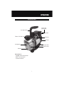
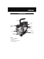
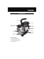
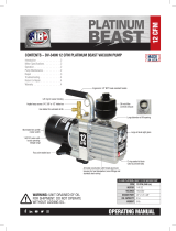
VPC Series Parts
7
Sure Grip Handle
Rubber Base
Fan Inlet
Electrical Box
Exhaust / Oil Refill Cap
Oil Sightglass
Oil Drain
Inlet Ports
Power Cord
(Not Shown)
Oil Reservoir
Unit consists of:
•
Pro-Set
®
model vacuum pump
• CPS
®
vacuum pump oil
• Operational manual.

OPERATION
8
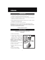
Vacuum Pump Operation
Initial Preparation
WARNING: Do not operate on systems under pressure.
Damage to the pump may occur.
1. Check the correct power supply outlet to
be used.
2. The VP series is equipped with a dual
voltage motor. Make sure the voltage
selector switch is set for the desired
voltage operation.
Caution: The motor will overheat and
trip the thermal protector if the voltage
selector and the power supply voltage do
not match.
3. Connect the correct power cord from
vacuum pump to power supply outlet.
4. Check oil level in vacuum pump.
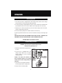
1. If the vacuum pump is equipped with a dual voltage motor, make sure the voltage
selector switch is set for the desired voltage operation.
2. The vacuum pump is shipped without oil in the reservoir. Remove the exhaust/oil fill
cap and add oil until it is seen in the middle of the oil sight glass. Re-secure cap.
3. Remove the 1/4" inlet service port cap, turn on the vacuum pump. After 15 seconds,
replace 1/4 cap back on inlet port.
4. Re-check vacuum pump oil level. Add or remove oil if necessary.
To achieve good final vacuum levels, the oil level should be visually seen through sight
glass.
CAUTION: DO NOT RUN THIS EQUIPMENT WITH LOW OR NO OIL. RUNNING THIS
EQUIPMENT WITH NO LUBRICATION WILL CAUSE PREMATURE FAILURE.
VACUUM PUMP IS NOW READY FOR USE.
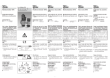
Figure - 1

OPERATION
9
Routine Maintenance
It is recommended to change the vacuum pump oil after 50 hours of usage. The purity of
the oil will determine the final vacuum level achieved. Always use the CPS recommended
vacuum pump oil (VPOQ / VPOP / VPOG). The oil provided with the pump has been
specially blended to maintain maximum visosity at normal running temperatures as well
as cold weather starts.
OIL CHANGE PROCEDURES:
1. Be sure the pump oil is warmed up. if not warm, turn vacuum pump “ON” for 10
minutes.
2. Make sure vacuum pump is not plugged in.
3. Remove the oil drain cap and drain the contaminated oil into a suitable container. Tilt
the vacuum pump toward the oil drain port.
4. Once all the oil has been drained, re-secure the oil drain cap back onto the oil drain
port.
5. Remove the exhaust / oil fill cap and add oil until it is seen in the middle of the oil sight
glass. Re-secure exhaust/oil fill cap.
5. Connect vacuum pump as shown in Figure - 1.
6. Open manifold valves.
7. Turn vacuum pump power switch “ON”.
8. Run vacuum pump until final vacuum level is met.
9. Once the final vacuum level is reached, close manifold valves, turn power switch
“OFF”.
VACUUM OPERATION COMPLETE

OPERATION
10
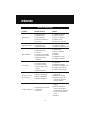
Troubleshooting Chart
Condition Possible Problem Solution
Unusually noisy
1. Bad bearings.
2. Loose motor bolts.
3. Coupling drive.
4. Dirty, low, or improper oil.
5. Air leaks in connections.
1. Replace motor.
2. Tighten bolts.
3. Adjust or replace coupling.
4. Replace oil.
5. Fix leaks.
High temperature
1. Low or improper voltage.
2. Worn bearings.
3. Low oil level.
1. Check power source
voltage.
2. Replace motor.
3. Add or replace.
Poor vacuum
1. System leaks.
2. Low oil level.
3. Dirty oil.
4. Air leaks at connection.
5. Air leak through seal.
6. Worn rotary mechanism.
1. Fix leaks.
2. Add or replace oil.
3. Flush and replace oil.
4. Fix leaks.
5. Replace shaft seal.
6. Replace cartridge.
Oil leaks
1. Oil leaks through exhaust.
2. Oil leaks through shaft seal.
3. Oil leaks through
reservoir.
4. System vented pressure.
5. Pump tipped over.
1. Oil level too high.
2. Replace shaft seal.
3. Tighten bolts or replace
gasket.
4. Check oil level.
5. Check oil level.
Pump does not start
1. No power to motor.
2. Damaged motor.
3. Thermal cutout.
1. Check fuses in IEC panel.
2. Replace motor.
3. Wait for thermal switch
to reset. Check for cause of
thermal.
Thermal cutout
1. Low or incorrect voltage.
2. Cold weather.
3. Dirty Oil.
1. Check voltage, move
voltage selector switch to
correct setting.
2. Start and run vacuum
pump with the intake
fitting open for 1 minute
to warm up oil.
3. Flush and replace oil.

WARRANTY
11
CPS
®
Products, Inc. guarantees that all products are free of manufacturing and material
defects to the original owner for one year from the date of purchase. If the equipment
should fail during the guarantee period it will be repaired or replaced (at our option)
at no charge. This guarantee does not apply to equipment that has been altered, mis-
used or solely in need of field service maintenance. All repaired equipment will carry
an independent 90-day warranty. This repair policy does not include equipment that is
determined to be beyond economical repair.
Contact Us
Web : www.cpsproducts.com
Email: [email protected]
CPS Products, Inc.
CPS Products, Inc. U.S.A. (Headquarters)
1010 East 31st Street, Hialeah, Florida 33013, USA
Tel: 305-687-4121, 1-800-277-3808, Fax: 305-687-3743
E-mail: [email protected] www.cpsproducts.com
CPS Canada
4605 Crysler Ave. Niagara Falls, Ontario L2E 3V6
Tel: 905-358-3124, Fax: 905-358-7187, 1-866-629-3895,
E-mail: [email protected]
CPS Products N.V
Krijgsbaan 241, 2070 Zwijndrecht, Belgium
Tel: (323) 281 30 40, Fax: (323) 281 65 83, www.cpsproducts.be,
E-mail: [email protected]
CPS Australia PTY. LTD.
109 Welland Avenue, Welland, South Australia 5007
Tel: +61 8 8340 7055, Fax: +61 8 8340 7033
E-mail: [email protected]

#70-168
www.cpsproducts.com

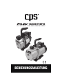
POMPE A VIDE
VP & VPC UNIQUE - DOUBLE ÉTAPE POMPE A VIDE
MANUEL D’INSTRUCTIONS

INFORMATIONS GÉNÉRALES
2
Merci d’avoir choisi une pompe de la série CPS
®
PROSET
®
VP. Ces pompes ont été
conçues pour le service dans le domaine du froid et de l’air conditionnée. La série VP
utilise un moteur électrique (1/2ch.) et une cartouche rotatif de pompe à vide.
Spécifications supplémentaires:
* Equipé d’CPS exclusif de brouillard d’huile gratuit Port d’échappement.
• VP modèles de la série à deux étages équipé d’une soupape de lest.
• Dual voltage modèles, la pompe peut être opéré aussi bien en 220v qu’en 110v
• Manche ergonomique, facilitant la portabilité
• Base en caotchouc pour positonement stable
• Refroidisement par air pour positonement stable
• Lecture de vacuum par 10-15 microns (2 étapes) et 50-100 microns (1 étape)
• Connecteur a entrées multiples, pour connections correspondentes
• Le drainage d’huile facilite le maintenance de la pompe par son accessibilité facile
• Le niveau d’huile est visible par la visière au dessus de la valve de drainage
Veuillez continuer la lecture des instructions a fin d’avoir un bon départ. Ce manuel
contient d’importantes instructions pour l’usage de cet équipement. Faites toujours
attention aux REMARQUES . N’oubliez pas, toujours la sécurité d’abord !
Table de Matières
Introduction
Information Générales 2-5
Introduction 2
Consignes de Sécurite 3
Spécifications
4-5
Opération 6-10
VP & VPC Série de Piéces 6-7
Prépartion Initiale 8
Opération de Pompe 8-9
Maintenance de Routine 9
Tableau de Dépannage 10
Garantie 11

INFORMATIONS GÉNÉRALES
3
Consignes de Sécurité
L’utilisation de ce matériel se fait de préférence que par du personnel qualifié.
Ce matériel est conçu pour l’évacuation finale d’un système frigorifique. L’utilisation
sur un circuit avec une pression supérieure à 5psi peut endommager la pompe à
vide.
DANGER - Eviter la respiration des gas
réfrigérants ou vapeur de lubrifiant.
L’inhalation de hautes concentrations de
réfrigérants peut causer des problèmes
cardiaques, l’inconscience ou même as-
phyxions.
DANGER - Chocque électrique: toujours
déconnecter le câble pendant les opéra-
tions de maintenance de la pompe.
PRÉVENTION - Ne pas brancher la pompe
sur un circuit sous pression.
ATTENTION - Tous les tuyaux peuvent con-
tenir de liquide sous pression. Le contact
avec ce liquide peut causer des brûlures.
Portez des lunettes et gants protectrices.
Soyez toujours prudent en déconnectant
des tuyaux.
ATTENTION - Inhalations de gas réfri-
gérants peut causer des irritations. Lisez
les données de sécurité du fabriquant pour
amples informations sur les lubrifiants et
réfrigérants.
ATTENTION - Afin d’éviter le risqué de feu,
ne pas utiliser des rallonges avec un di-
amètre de moins de (2,5mm
2
).
ATTENTION - Ne jamais utiliser l’équipement
près de liquides inflammables. Contrôlez
les consignes de sécurité avant usage.

INFORMATIONS GÉNÉRALES
4
Spécifications
* «Vierge» = Bi-tension (110-120 / 220 50/60Hz E = 220-240V 50/60Hz J = 100V 50/60Hz U = 115V 50/60Hz
Modèle VPC2S* VPC4S* VP2S* VP4S* VP6S*
Etape 1 1
Puissande (CP) RPM @ 50/60Hz
1/5
2880 / 3440
1/4
2880 / 3440
1/4
1440 / 1720
1/3
2880 / 3440
1/2
2880 / 3440
Dimensions (Puches) 9.1 x 4.5 x 8.0 11.3 x 4.5 x 8.0 12.2 x 5 x 9.6 13.1 x 5.5 x 10
Poids 9.3 lb / 4.2 kg 11.0 lb / 5 kg 13.7 lb / 6.2 kg 15.0 lb / 6.8 kg 18.3 lb / 8.3 kg
Température D’Opération 0˚C (32˚F) to 52˚C (125˚F)
Source* U, E, J Dual
Vacuum Ultime aussi bas que 100 Microns 50 Microns
Capacité D’Hulle 9 oz / 250 ml 10 oz / 300 ml 16 oz / 470 ml 16 oz / 470 ml 19 oz / 550 ml
Construction Caisse en aluminium sur base en caoutchouc et manche pvc
Protection Surcharge Protection thermale du moteur
Controle Par interrupteur
Déplacement D’Air
2 CFM @ 60H
48 l/m @ 50Hz
4 CFM @ 60Hz
96 l/m @ 50Hz
2 CFM @ 60Hz
48 l/m @ 50Hz
4 CFM @ 60Hz
96 l/m @ 50Hz
6 CFM @ 60Hz
144 l/m @ 50Hz
Connecteurs 1/4 SAE & 1/2 ACME 1/4 SAE, 3/8 SAE & 1/2 ACME
Vanne A Décharde Non

INFORMATIONS GÉNÉRALES
5
Spécifications
* «Vierge» = Bi-tension (110-120 / 220 50/60Hz E = 220-240V 50/60Hz J = 100V 50/60Hz U = 115V 50/60Hz
Modèle VPC2D* VP2D* VP4D* VP6D* VP8D* VP10D* VP12D*
Etape 2
Puissande (CP) RPM @
50/60Hz
1/4
2880 / 3440
1/3
1440 / 1720
1/2
2880 / 3440
1/2
2880 / 3440
2/3
2880 / 3440
3/4
2880 / 3440
1
2880 / 3440
Dimensions (Puches)
11.3 x 4.5
x 8.0
12.2 x 5 x 9.6 13.1 x 5.5 x 10 14.9 x 5.7 x 10.6
Poids
12.1 lb /
5.5 kg
17.7 lb /
8.0 kg
22.1 lb /
10.0 kg
22.5 lb /
10.2kg
29.8 lb /
13.5kg
30.3 lb /
13.7kg
30.9 lb /
14.0kg
Température D’Opération 0˚C (32˚F) to 52˚C (125˚F)
Source* E, U, J Dual, E, J Dual, J
Vacuum Ultime 15 Microns 10 Microns
Capacité D’Hulle
9 oz /
250ml
11.5 oz /
330ml
15.5 oz /
450ml
14 oz /
400 ml
29 oz/
860 ml
28 oz /
830 ml
27 oz /
800 ml
Construction Caisse en aluminium sur base en caoutchouc et manche pvc
Protection Surcharge Protection thermale du moteur
Controle Protection thermale du moteur
Déplacement D’Air
2 CFM @
60Hz
48 l/m @
50Hz
2 CFM @
60Hz
48 l/m @
50Hz
4 CFM @
60Hz
96 l/m @
50Hz
6 CFM @
60Hz
144 l/m @
50Hz
8 CFM @
60Hz
192 l/m @
50Hz
10 CFM @
60Hz
240 l/m @
50Hz
12 CFM @
60Hz
288 l/m @
50Hz
Connecteurs
1/4 SAE &
1/2 ACME
1/4 SAE, 3/8 SAE, & 1/2 ACME 1/4, 3/8 & 1/2 SAE
Vanne A Décharde Non Oui

OPÈRATION
6
VP Série de Pièces
Manche
Vanne de décharge
(seulement sur le modèles a
étapes)
Base en Caoutchouc
Réservoir
D’Huile
Entrée
Ventilateur
Boite
Électrique
Echapement /
Capuchon de
drainage
Visière
Drainage
D’Huile
Entrée
Entrée Électrique /
Boitea Plomb (Dans
prise IEC)
Contenu:
• Pompe à vide
PRO-SET
®
• Cable 220 volt
• Huile pour pompe a vide, 500 ml
• Manuel d’instructions

OPÈRATION
VPC Série de Pièces
7
Manche
Base en Caoutchouc
Réservoir
D’Huile
Entrée
Ventilateur
Boite
Électrique
Echapement /
Capuchon de
drainage
Visière
Drainage
D’Huile
Entrée
Contenu:
• Pompe à vide
PRO-SET
®
• Cable 220 volt
• Huile pour pompe a vide, 500 ml
• Manuel d’instructions

OPÈRATION
8
Opération de Pompe
Prépartion Initiale
CAUTION: Ne pas utiliser la pompe sur des circuits
sous pression.
1. Contrôler le type de voltage.
2. Si la pompe à vide est équipé d’un moteur
à double tension, s’assurer que le
sélecteur de tension est réglé pour le
fonctionnement de tension souhaité.
Attention: Le moteur surchauffera et la
protection thermale sera enclenchée au
cas de voltage incorrecte.
3. Brancher le cable de courant au circuit.
4. Contrôler le niveau d’huile.
5. Connecter la pompe comme montrée en
Figure - 1.
6. Ouvrir les vannes manifold.
7. Enclencher par la touché "ON".
1. Si la pompe à vide est équipé d’un moteur à double tension, s’assurer que le sélecteur
de tension est réglé pour le fonctionnement de tension souhaité.
2. La pompe est livré SANS huile dans le réservoir ! Verser l’huile par l’ouverture de
remplissage et contrôler le niveau dans la visière.
3. Enlever le capuchon de l’netrée 1/4, allumer la pompe. Après 15 secondes, remettre
le capuchon 1/4 sur la bouche d’entrée.
4. Re-contrôler le niveau d’huile et ajouter si nécessaire.
Afin d’obtenir un vide correcte le niveau d’huile doit être bien visible par la visière.
ATTENTION: Ne pas utiliser la pompe avec peu ou pas d’huile. Utilisage sans lubrifi-
cation résultera enendommagement prémature.
La pompe est prête à être utilisée.
Figure - 1
La page charge ...
La page charge ...
La page charge ...
La page charge ...
La page charge ...
La page charge ...
La page charge ...
La page charge ...
La page charge ...
La page charge ...
La page charge ...
La page charge ...
La page charge ...
La page charge ...
La page charge ...
La page charge ...
La page charge ...
La page charge ...
La page charge ...
La page charge ...
La page charge ...
La page charge ...
La page charge ...
La page charge ...
La page charge ...
La page charge ...
La page charge ...
La page charge ...
-
 1
1
-
 2
2
-
 3
3
-
 4
4
-
 5
5
-
 6
6
-
 7
7
-
 8
8
-
 9
9
-
 10
10
-
 11
11
-
 12
12
-
 13
13
-
 14
14
-
 15
15
-
 16
16
-
 17
17
-
 18
18
-
 19
19
-
 20
20
-
 21
21
-
 22
22
-
 23
23
-
 24
24
-
 25
25
-
 26
26
-
 27
27
-
 28
28
-
 29
29
-
 30
30
-
 31
31
-
 32
32
-
 33
33
-
 34
34
-
 35
35
-
 36
36
-
 37
37
-
 38
38
-
 39
39
-
 40
40
-
 41
41
-
 42
42
-
 43
43
-
 44
44
-
 45
45
-
 46
46
-
 47
47
-
 48
48


dans d''autres langues
Documents connexes
Autres documents
-
MasterCool 90068-2V-110-BL Mode d'emploi
-
Rothenberger Vacuum pump ROAIRVAC Manuel utilisateur
-
 Kromschroder Closed position switch Mode d'emploi
-
 JB DV-340N PLATINUM BEAST Manuel utilisateur
-
 Kromschroder CPS Mode d'emploi
-
-
Unbranded R7TQ Guide d'installation
-
NAPOLEON NT13A018C-1 Manuel utilisateur
-
-
Desa RC55T Le manuel du propriétaire


