Hitachi P 20DA Instruction Manual And Safety Instructions
- Catégorie
- Outils électroportatifs
- Taper
- Instruction Manual And Safety Instructions

P 20DA
MODE D’EMPLOI ET INSTRUCTIONS DE SECURITE
AVERTISSEMENT
Une utilisation incorrecte et dangereuse de cet outil motorisé peut entraîner la
mort ou de sérieuses blessures corporelles!
Ce mode d’emploi contient d’importantes informations à propos de la sécurité de
ce produit. Prière de lire et de comprendre ce mode d’emploi avant d’utiliser l’outil
motorisé. Garder ce mode d’emploi à la disponibilité des autres utilisateurs avant
qu’ils utilisent l’outil motorisé.
INSTRUCTION MANUAL AND SAFETY INSTRUCTIONS
WARNING
Improper and unsafe use of this power tool can result in death or serious bodily
injury!
This manual contains important information about product safety. Please read
and understand this manual before operating the power tool. Please keep this
manual available for others before they use the power tool.
MANUAL DE INSTRUCCIONES E INSTRUCCIONES DE SEGURIDAD
ADVERTENCIA
¡La utilización inapropiada e insegura de esta herramienta eléctrica puede resultar
en lesiones serias o en la muerte!
Este manual contiene información importante sobre la seguridad del producto.
Lea y comprenda este manual antes de utilizar la herramienta eléctrica. Guarde
este manual para que puedan leerlo otras personas antes de que utilicen la
herramienta eléctrica.
MODEL CORDLESS PLANER
MODÈLE RABOT À BATTERIE
MODELO CEPILLO A BATERÍA

CONTENTS
TABLE DES MATIERES
ÍNDICE
Página
MONTAJE Y OPERACIÓN....................................... 57
APLICACIONES ................................................... 57
MÉTODO DE EXTRACCIÓN E INSTALACIÓN
DE LA BATERÍA............................................ 57
MÉTODO DE CARGA .......................................... 58
ANTES DE LA UTILIZACIÓN .............................. 60
OPERACIÓN......................................................... 61
MONTAJE Y DESMONTAJE DE LA CUCHILLA DE
CARBURO Y AJUSTE DE LA ALTURA DE LA CUCHILLA
... 63
TIPO DE CUCHILLA DE DOBLE FILO ................. 63
TIPO DE CUCHILLA DE AFILABLE ..................... 65
AFILADO DE CUCHILLAS AFILABLES ................... 67
MANTENIMIENTO E INSPECCIÓN ........................ 68
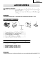
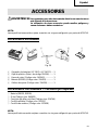
ACCESORIOS ........................................................... 69
ACCESORIOS ESTÁNDAR.................................. 69
ACCESORIOS OPCIONALES .............................. 69
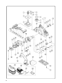
LISTA DE PIEZAS .................................................... 70
Français
Español
Página
INFORMACIÓN IMPORTANTE ........................... 48
SIGNIFICADO DE LAS PALABRAS DE SEÑALIZACIÓN
.. 48
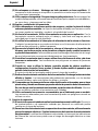
SEGURIDAD............................................................. 49
NORMAS GENERALES DE SEGURIDAD – PARA TODAS
LAS HERRAMIENTAS ALIMENTADAS CON BATERÍA
.. 49
NORMAS ESPECÍFICOS DE SEGURIDAD ......... 51
INSTRUCCIONES IMPORTANTES PARA LA
UTILIZACIÓN DEL CEPILLO A BATTERÍA ......
52
INSTRUCCIONES IMPORTANTES DE SEGURIDAD
PARA EL CARGADOR DE BATERÍAS
................. 52
INSTRUCCIONES IMPORTANTES DE SEGURIDAD
PARA LA BATERÍA Y EL CARGADOR DE BATERÍAS
... 53
DESCRIPCIÓN FUNCIONAL.................................... 55
MODELO .............................................................. 55
NOMENCLATURA............................................... 55
ESPECIFICACIONES............................................ 56
English
Page
IMPORTANT INFORMATION ............................. 3
MEANINGS OF SIGNAL WORDS....................... 3
SAFETY .................................................................... 4
GENERAL SAFETY RULES – FOR ALL
BATTERY OPERATED TOOLS..................... 4
SPECIFIC SAFETY RULES................................... 5
IMPORTANT SAFETY INSTRUCTIONS FOR
USE OF THE CORDLESS PLANER ................ 7
IMPORTANT SAFETY INSTRUCTIONS
FOR BATTERY CHARGER............................ 7
IMPORTANT SAFETY INSTRUCTIONS
FOR USE OF THE BATTERY AND
BATTERY CHARGER.................................... 8
FUNCTIONAL DESCRIPTION ................................ 10
MODEL............................................................... 10
NAME OF PARTS .............................................. 10
SPECIFICATIONS .............................................. 11
Page
ASSEMBLY AND OPERATION ............................. 12
APPLICATIONS.................................................. 12
REMOVAL AND INSTALLATION METHOD
OF BATTERY .................................................. 12
CHARGING METHOD........................................ 13
BEFORE USE ..................................................... 15
OPERATION....................................................... 16
CARBIDE BLADE ASSEMBLY AND
DISASSEMBLY AND ADJUSTMENT OF
BLADE HEIGHT .............................................. 18
DOUBLE EDGED BLADE TYPE ................. 18
RESHARPENABLE BLADE TYPE............... 20
SHARPENING THE RESHARPENABLE
BLADES .......................................................... 22
MAINTENANCE AND INSPECTION ..................... 23
ACCESSORIES ....................................................... 24
STANDARD ACCESSORIES ............................. 24
OPTIONAL ACCESSORIES ............................... 24
PARTS LIST............................................................ 70
Page
ASSEMBLAGE ET FONCTIONNEMENT ..........................
35
UTILISATIONS..................................................... 35
MÉTHODE DE RETRAIT ET D’INSTALLATION
DE LA BATTERIE .......................................... 35
MÉTHODE DE RECHARGE ................................. 36
AVANT L’UTILISATION ...................................... 38
UTILISATION ....................................................... 39
MONTAGE ET DEMONTAGE DE LA LAME AU
CARBURE ET REGLAGE DE LA HAUTEUR
DE LA LAME AU CARBURE................................ 41
LAME À DOUBLE TRANCHANT ..................... 41
LAME RÉAFFÛTABLE ..................................... 43
AFFÛTAGE DES LAMES REAFFÛTABLE .......... 45
ENTRETIEN ET INSPECTION .................................. 46
ACCESOIRES ........................................................... 47
ACCESSOIRES STANDARD ............................... 47
ACCESSOIRES EN OPTION................................ 47
LISTA DES PIÈCES ................................................. 70
Page
INFORMATIONS IMPORTANTES ...................... 25
SIGNIFICATION DES MOTS D’AVERTISSEMEN
T .... 25
SECURITE ................................................................ 26
REGLES GENERALE DE SECURITE – POUR TOUS
LES OUTILS FONCTIONNANT SUR BATTERIE ...
26
REGLES DE SECURITE SPECIFIQUES ............... 28
CONSIGNES DE SÉCURITÉ IMPORTANTES POUR
L'UTILISATION DU RABOT À BATTERIE
.......... 30
CONSIGNES DE SÉCURITÉ IMPORTANTES
POUR L’UTILISATION DU CHARGEUR DE BATTERIE ...
30
CONSIGNES DE SÉCURITÉ IMPORTANTES POUR L’UTILISATION
DE LA BATTERIE ET DU CHARGEUR DE BATTERIE ...............
31
DESCRIPTION FONCTIONNELLE ........................... 33
MODELE............................................................... 33
NOM DES PARTIES............................................. 33
SPECIFICATIONS ................................................ 34

English
3
IMPORTANT INFORMATION
Read and understand all of the operating instructions, safety precautions and warnings in
the Instruction Manual before operating or maintaining this power tool.
Most accidents that result from power tool operation and maintenance are caused by the
failure to observe basic safety rules or precautions. An accident can often be avoided by
recognizing a potentially hazardous situation before it occurs, and by observing appropriate
safety procedures.
Basic safety precautions are outlined in the “SAFETY” section of this Instruction Manual and
in the sections which contain the operation and maintenance instructions.
Hazards that must be avoided to prevent bodily injury or machine damage are identified by
WARNINGS on the power tool and in this Instruction Manual.
Never use this power tool in a manner that has not been specifically recommended by
HITACHI, unless you first confirm that the planned use will be safe for you and others.
MEANINGS OF SIGNAL WORDS
WARNING indicates a potentially hazardous situations which, if ignored, could result in
serious personal injury.
CAUTION indicates a hazardous situations which, if ignored, could result in moderate
personal injury, or could cause machine damage.
NOTE emphasizes essential information.

English
4
SAFETY
GENERAL SAFETY RULES – FOR ALL BATTERY OPERATED TOOLS
WARNING:Read and understand all instructions.
Failure to follow all instructions listed below, may result in electric
shock, fire and/or serious personal injury.
SAVE THESE INSTRUCTIONS
1. Work Area
(1) Keep your work area clean and well lit. Cluttered benches and dark areas invite
accidents.
(2) Do not operate power tools in explosive atmospheres, such as in the presence of
flammable liquids, gases, or dust. Power tools create sparks which may ignite the
dust of fumes.
(3) Keep bystanders children, and visitors away while operating a power tool.
Distractions can cause you to lose control.
2. Electrical Safety
(1) A battery operated tool with integral batteries or a separate battery pack must be
recharged only with the specified charger for the battery.
A charger that may be suitable for one type of battery may create a risk of fire when
used with another batttery.
(2) Use battery operated tool only with specifically designed battery pack.
Use of any other batteries may create a risk of fire.
3. Personal Safety
(1) Stay alert, watch what you are doing and use common sense when operating a
power tool. Do not use tool while tired or under the influence of drugs, alcohol, or
medication. A moment of inattention while operating power tools may result in
serious personal injury.
(2) Dress properly. Do not wear loose clothing or jewelry. Contain long hair. Keep your
hair, clothing and gloves away from moving parts. Loose clothes, jewelry, or long hair
can be caught in moving parts.
(3) Avoid accidental starting. Be sure switch is off before plugging in. Carrying tools with
your finger on the switch or plugging in tools that have the switch on invites accidents.
(4) Remove adjusting keys or wrenches before turning the tool on. A wrench or a key that
is left attached to a rotating part of the tool may result in personal injury.
(5) Do not overreach. Keep proper footing and balance at all times. Proper footing and
balance enables better control of the tool in unexpected situations.
(6) Use safety equipment. Always wear protective grasses. Dust mask, nonskid safety
shoes, hard hat, or ear plugs must be used for appropriate conditions.

English
5
4. Tool Use and Care
(1) Use clamps or other practical way to secure and support the workpiece to a stable
platform. Holding the work by hand or against your body is unstable and may lead to
loss of control.
(2) Do not force tool. Use the correct tool for your application. The correct tool will do
the job better and safer at the rate for which it is designed.
(3) Do not use tool if switch does not turn it on or off. Any tool that cannot be controlled
with the switch is dangerous and must be repaired.
(4) Disconnect battery pack from tool or place the switch in the locked or off position
before making any adjustments, changing accessories, or storing the tools. Such
preventive safety measures reduce the risk of starting the tool accidentally.
(5) Store idle tools out of reach of children and other untrained persons. Tools are
dangerous in the hands of untrained users.
(6) When battery pack is not in use, keep it away from other metal objects like: paper
clips, coins, keys, nails, screws, or other small metal objects that can make a
connection from one terminal to another.
Shorting the battery terminals together may cause sparks, burns, or a fire.
(7) Maintain tools with care. Keep cutting tools sharp and clean. Properly maintained
tools, with sharp cutting edges are less likely to bind and are easier to control.
(8) Check for misalignment or binding of moving parts, breakage of parts, and any other
condition that may affect the tools operation. If damaged, have the tool serviced
before using. Many accidents are caused by poorly maintained tools.
(9) Use only accessories that are recommended by the manufacturer for your model.
Accessories that may be suitable for one tool, may become hazardous when used on
another tool.
5. Service
(1) Tool service must be performed only by qualified repair personnel. Service or
maintenance performed by unqualified personnel could result in a risk of injury.
(2) When servicing a tool, use only identical replacement parts. Follow instructions in
the Maintenance section of this manual. Use of unauthorized parts or failure to follow
Maintenance Instruction may create a risk of electric shock or injury.
SPECIFIC SAFETY RULES
1. Hold tools by insulated gripping surfaces when performing an operation where the
cutting tool may contact hidden wiring or its own cord. Contact with a “live” wire will
make exposed metal parts of the tool “live” and shock the operator.
2. Never touch moving parts.
Never place your hands, fingers or other body parts near the tool’s moving parts.
3. Never operate without all guards in place.
Never operate this tool without all guards or safety features in place and in proper
working order. If maintenance or servicing requires the removal of a guard or safety
feature, be sure to replace the guard or safety feature before resuming operation of the
tool.
4. Use right tool.
Don’t force small tool or attachment to do the job of a heavy-duty tool.
Don’t use tool for purpose not intended —for example— don’t use circular saw for cutting
tree limbs or logs.

English
6
5. Never use a power tool for applications other than those specified.
Never use a power tool for applications other than those specified in the Instruction
Manual.
6. Handle tool correctly.
Operate the tool according to the instructions provided herein. Do not drop or throw the
tool. Never allow the tool to be operated by children, individuals unfamiliar with its
operation or unauthorized personnel.
7. Definitions for symbols
V ...... volts
--- ................ direct current
n
o
................ no load speed
---/min ........ revolutions or reciprocation per minute
8. Keep all screws, bolts and covers tightly in place.
Keep all screws, bolts, and plates tightly mounted. Check their condition periodically.
9. Do not use power tools if the plastic housing or handle is cracked.
Cracks in the tool’s housing or handle can lead to electric shock. Such tools should not
be used until repaired.
10.Blades and accessories must be securely mounted to the tool.
Prevent potential injuries to youself or others. Blades, cutting implements and accesso-
ries which have been mounted to the tool should be secure and tight.
11.Never use a tool which is defective or operating abnormally.
If the tool appears to be operating unusually, making strange noises, or otherwise
appears defective, stop using it immediately and arrange for repairs by a Hitachi
authorized service center.
12.Carefully handle power tools.
Should a power tool be dropped or struck against hard materials inadvertently, it may be
deformed, cracked, or damaged.
13.Do not wipe plastic parts with solvent.
Solvents such as gasoline, thinner benzine, carbon tetrachloride, and alcohol may
damage and crack plastic parts. Do not wipe them with such solvents.
Wipe plastic parts with a soft cloth lightly dampened with soapy water and dry
thoroughly.

English
7
IMPORTANT SAFETY INSTRUCTIONS FOR USE OF THE
CORDLESS PLANER
WARNING:Death or serious bodily injury could result from improper or unsafe use
of the cordless planer. To avoid these risks, follow these basic safety
instructions:
1. Never use the planer with the blades facing upward (as a stationary type planer).
2. Never insert finger and so into the outlet of shaving while operating.
IMPORTANT SAFETY INSTRUCTIONS FOR BATTERY CHARGER
1. This manual contains important safety and operating instructions for battery charger
Model UC 14YF/UC14YF2.
2. Before using battery charger, read all instructions and cautionary markings on (1) battery
charger, (2) battery, and (3) product using battery.
3. To reduce risk of injury, charge HITACHI rechargeable battery type EB7, EB9, EB12, EB14
series. Other type of batteries may burst causing personal injury and damage.
4. Do not expose battery charger to rain or snow.
5. Use of an attachment not recommended or sold by the battery charger manufacturer may
result in a risk of fire, electric shock, or injury to persons.
6. To reduce risk of damage to electric plug and cord, pull by plug when disconnecting
battery charger.
7. Make sure cord is located so that it will not be stepped on, tripped over, or otherwise
subjected to damage or stress.
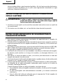
8. An extension cord should not be used unless absolutely necessary. Use of improper
extension cord could result in a risk of fire and electric shock.
If extension cord must be used make sure:
a. That blades of extension cord are the same number, size, and shape as those of plug
on battery charger:
b. That extension cord is properly wired and in good electrical condition; and
c. That wire size is large enough for AC ampere rating of battery charger as specified
in Table 1.

English
8
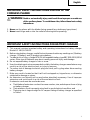
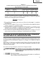
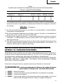
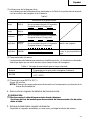
Table 1
RECOMMENDED MINIMUM AWG SIZE FOR
EXTENSION CORDS FOR BATTERY CHARGERS
AC Input Rating Amperes* AWG Size of Cord
Equal to or but less Length of Cord, Feet (Meter)
greater than than 25 (7.5) 50 (15) 100 (30) 150 (45)
0 2 18 18 18 16
2 3 18 18 16 14
3 4 18 18 16 14
1250watts
125 volts
= 10 amperes
* If the input rating of a battery charger is given in watts rather than in amperes, the
corresponding ampere rating is to be determined by dividing the wattage rating by the
voltage rating–for example:
9. Do not operate battery charger with damaged cord or plug-replace them immediately.
10.Do not operate battery charger if it has received a sharp blow, been dropped, or otherwise
damaged in any way; take it to a qualified serviceman.
11.Do not disassemble battery charger; take it to a qualified serviceman when service or
repair is required. Incorrect reassembly may result in a risk of electric shock or fire.
12.To reduce risk of electric shock, unplug charger from receptacle before attempting any
maintenance or cleaning. Removing the battery will not reduce this risk.
IMPORTANT SAFETY INSTRUCTIONS FOR USE OF THE
BATTERY AND BATTERY CHARGER
You must charge the battery before you can use the cordless planer. Before using the model
UC 14YF/UC14YF2 battery charger, be sure to read all instructions and cautionary state-
ments on it, the battery and in this manual.
REMEMBER: USE ONLY HITACHI BATTERY TYPES EB7 SERIES, EB9 SERIES, EB12 SERIES,
EB14 SERIES. OTHER TYPES OF BATTERIES MAY BURST AND CAUSE INJURY!
Follow these instructions to avoid the risk of injury:
WARNING:Improper use of the battery or battery charger can lead to serious injury.
To avoid these injuries:
1. NEVER disassemble the battery.
2. NEVER incinerate the battery, even if it is damaged or is completely worn out. The
battery can explode in a fire.
3. NEVER short-circuit the battery.
4. NEVER insert any objects into the battery charger’s air vents. Electric shock or
damage to the battery charger may result.

English
9
5. NEVER charge outdoors. Keep the battery away from direct sunlight and use only
where there is low humidity and good ventilation.
6. NEVER charge when the temperature is below 32°F (0°C) or above 104°F (40°C).
7. NEVER connect two battery chargers together.
8. NEVER insert foreign objects into the hole for the battery or the battery charger.
9. NEVER use a booster transformer when charging.
10. NEVER use an engine generator or DC power to charge.
11. NEVER store the battery or battery charger in places where the temperature may
reach or exceed 104°F (40°C).
12. ALWAYS operate charger on standard household electrical power (120 volts). Using
the charger on any other voltage may overheat and damage the charger.
13. ALWAYS wait at least 15 minutes between charges to avoid overheating the charger.
14. ALWAYS disconnect the power cord from its receptacle when the charger is not in use.
SAVE THESE INSTRUCTIONS
AND
MAKE THEM AVAILABLE TO
OTHER USERS OF THIS TOOL!

English
10
MODEL
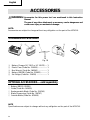
P 20DA: with charger (UC 14YF or UC 14YF2), battery and case
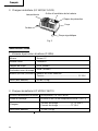
NAME OF PARTS
1. Cordless Planer (P 20DA)
䡬 Battery (EB12B)
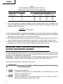
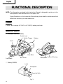
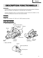
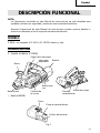
FUNCTIONAL DESCRIPTION
NOTE: The information contained in this Instruction Manual is designed to assist you in the
safe operation and maintenance of the power tool.
Some illustrations in this Instruction Manual may show details or attachments that
differ from those on your own power tool
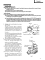
Fig. 1
Nameplate
Latch
Terminal Hole
Knob
Front Base
Belt Cover
Rear Base
Switch Lock
Switch Trigger
Battery
Outlet of Shaving
Nameplate

English
11
Input power source Single phase: AC120V 60Hz
Charging time Approx. 60min. (At a temperature of 68°F (20°C))
Charger
Charging voltage .....................................DC 7.2–14.4V
Charging current.............................................. DC 1.9A
Weight 2.9 lbs (1.3kg)
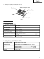
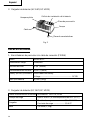
2. Battery Charger (UC 14YF/UC 14YF2)
2. Battery Charger (UC 14YF/ UC 14YF2)
SPECIFICATIONS
1. Cordless Planer (P 20DA)
Motor DC motor
No-load speed
13000/min
Cutting Width 3-1/4″ (82mm)
Max. Cutting Depth 5/256″ (0.5mm)
Battery (EB12B) (2000mAh) Nickel cadmium battery
Voltage ............................................................... DC12V
Weight (with Battery) 6.4 lbs (2.9 kg)
Pilot Lamp
Cord
Battery Installation Hole
Caution Plate
Body
Fig. 2
Nameplate

English
12
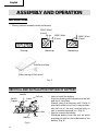
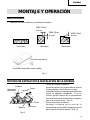
ASSEMBLY AND OPERATION
APPLICATIONS
䡬 Planing various wooden planks and panels.
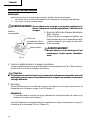
REMOVAL AND INSTALLATION METHOD OF BATTERY
䡬 How to install the battery.
Align the battery with the groove in tool tail
and slip it into place.
Always insert it all the way until it locks in
place with a little click, If not, it may acciden-
tally fall out of the tool, causing injury to
you or someone around you. (Fig. 4)
䡬 How to remove the battery.
Withdraw battery from the tool tail while
pressing the latch on the underneath of the
battery. (Fig. 4)
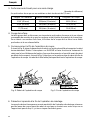
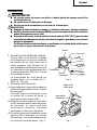
(Side planing of flush door)
Fig. 3
Fig. 4
Battery
Push
Latch
Pull out
15/64" (Max)
(6 mm)
15/64" (Max)
(6 mm)
15/64" (Max)
(6 mm)
Switch
Trigger
Handle
Insert
Side face cutting
(Planing) (Beveling) (Rabbeting)

English
13
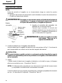
CHARGING METHOD
NOTE: Before plugging into the receptacle, make sure the following points.
䡬 The power source voltage is stated on the nameplate.
䡬 The cord is not damaged.
WARNING:Do not charge at voltage higher than indicated on the nameplate.
If charged at voltage higher than indicated on the nameplate, the
charger will burn up.
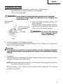
1. Insert the plug of battery charger into
the receptacle.
When the plug of battery charger has been
inserted into the receptacle, pilot lamp will
blink in red. (At 1-second intervals)
WARNING:Do not use the electrical
cord if damaged. Have it
repaired immediately.
2. Insert the battery to the battery charger.
Insert the battery into the battery charger as shown in Fig. 5. Make sure it contacts the
bottom of the battery charger.
CAUTION:
● If the batteries are inserted in the reverse direction, not only recharging will become
impossible, but it may also cause problems in the charger such as a deformed recharging
terminal.
3. Charging
When the battery is connected to the battery charger, charging will commence and the
pilot lamp will light in red. (See Table 2)
NOTE: If the pilot lamp flikers in red, pull out the plug from the receptacle and check if
the battery is properly mounted.
When the battery is fully charged, the pilot lamp will bilink in red slowly. (At 1-second
intervals) (See Table 2)
Pilot lamp
d
Fig. 5
Rechargeable
battery
Insert
Hole for connecting
the rechargeable
battery

English
14
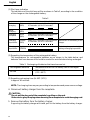
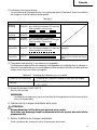
(1) Pilot lamp indication
The indications of the pilot lamp will be as shown in Table 2, according to the condition
of the charger or the rechargeable battery.
(2) Regarding the temperature of the rechargeable battery.
The temperatures for rechargeable batteries are as shown in the table below, and
batteries that have become hot should be cooled for a while before being recharged.
(3) Regarding recharging time (At 68°F (20°C))
In approx. 60 minutes.
NOTE: The charging time may vary according to temperature and power source voltage.
4. Disconnect battery charger from the receptacle.
CAUTION:
Do not pull the plug out of the receptacle by pulling on the cord.
Make sure to grasp the plug when removing from receptacle to avoid damaging cord.
5. Remove the battery from the battery charger.
Supporting the battery charger with hand, pull out the battery from the battery charger.
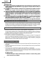
Table 2
Indications of the pilot lamp
Lights for 0.5 seconds. Does not light for
0.5 seconds. (off for 0.5 seconds)
Lights continuously
Lights for 0.5 seconds. Does not light for
0.5 seconds. (off for 0.5 seconds)
Lights for 0.1 seconds. Does not light for
0.1 seconds. (off for 0.1 seconds)
Lights continuously
Before
charging
While
charging
Charging
complete
Charging
impossible
Charging
impossible
Malfunction in the battery or the
charger
The battery temperature is high,
making recharging impossible.
Blinks
(RED)
Lights
(RED)
Blinks
(RED)
Flickers
(RED)
Lights
(GREEN)
Table 3 Recharging of batteries that have become hot
Temperatures at which the battery can be recharged
23°F—140°F
(–5°C—60°C)
Rechargeable batteries
EB 12B

English
15
CAUTION:
● When the battery charger has been continuosly used, the battery charger will heated,
thus constituting the cause of the failures. Once the charging has been completed, give
15 minutes rest until the next charging.
● If the battery is rechraged when it is warm due to battery use or exposure to sunlight,
the pilot lamp may light in green.
The battery will not be recharged. In such a case, let the battery cool before charging.
● When the pilot lamp flickers rapidly in red (at 0.2–second intervals), check for and take
out any foreign objects in the charger’s battery installation hole. If there are no foreign
objects, it is probable that the battery or charger is malfunctioning. Take it to your
authorized Service Center.
● Since the built-in micro computer takes about 3 seconds to confirm that the battery
being charged with UC 14YF/UC 14YF2 is taken out, wait for a minimum of 3 seconds
before reinserting it to continue charging. If the battery is reinserted within 3 seconds,
the battery may not be properly charged.
Regarding electric discharge in case of new batteries, etc.
As the internal chemical substance of new batteries and batteries that have not been
used for an extended period is not activated, the electric discharge might be low when
using them the first and second time. This is a temporary phenomenon, and normal time
required for recharging will be restored by recharging the batteries 2 – 3 times.
How to make the batteries perform longer.
(1) Recharge the batteries before they become completely exhausted.
When you feel that the power of the tool becomes weaker, stop using the tool and
recharge its battery. If you continue to use the tool and exhaust the electric current, the
battery may be damaged and its life will become shorter.
(2) Avoid recharging at high temperatures.
A rechargeable battery will be hot immediately after use. If such a battery is recharged
immediately after use, its internal chemical substance will deteriorate, and the battery
life will be shortened. Leave the battery and recharge it after it has cooled for a while.
BEFORE USE
䡬 Check the work area to make sure that it is clear of debris and clutter.
䡬 Clear the area of unnecessary personnel. Ensure that lighting and ventilation is adequate.
䡬 Confirm that the cutter blades are securely tightened
The cutter blade is securely bolted at the factory, rendering the machine immediately
usable on site : however, use a box wrench to retighten the bolts prior to operation.
CAUTION:
Checking the battery.
Make sure that the battery is installed firmly : If it is at all loose it can foll off and cause
an accident.

English
16
OPERATION
WARNING:
● Never place your hands, fingers or other body parts near the rotating blades.
● Never hold switchlock.
● Never carry a tool with a finger on the switch.
CAUTION:
● Pull out battery after finished operating, and while taking break.
● Never use type EB12M battery, because maybe near terminal is distorted by heat.
● Before use, try to cool the battery (above 115°F (45° C)) which became hot immedi-
ately after being charged or stored in a vehicle during transportation. If the battery
is used while still hot, it is likely that the battery case will undergo thermal
deformation or its service life will be shortened.
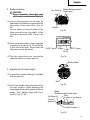
1. Adjusting the cutting depth:
Turn the knob in the direction indicated
by the arrow in Fig. 6 (clockwise), until the
triangular mark is aligned with the desired
cutting depth on the scale.
An interval between graduations on the
scale corresponds to 1/256" (0.1 mm) in
cutting depth.
The cutting depth can be adjusted within
a range of 0 – 5/256" (0 – 0.5 mm).
2. Operation of switch
(1) For safe operation of the machine, a
“switch lock” is provided on the side of a
handle.
If the “switch lock” is pulled in a state
where it is pressed in the direction of the
arrow mark, the switch can be turned ON.
(2) After the switch is turned ON, even when
you release your hand from the switch
lock, the body continues running as long
as you keep on pulling the switch trigger.
(3) If you release the switch trigger, you can
turn OFF the switch and the “switch lock”
returns to the home position
automatically. (Fig. 7)
Fig. 6
Switch Lock
Switch Trigger
Fig. 7
Triangular
Mark
Knob
Graduation

English
17
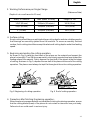
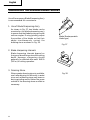
3. Working Performance per Single Charge
(Reference Data)
4. Surface cutting
Rough cutting should be accomplished at large cutting depths and at a suitable speed so
that shavings are smoothly ejected from the machine. To ensure a smoothly finished
surface, finish cutting should be accomplished at small cutting depths and at low feeding
speed.
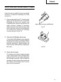
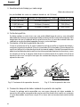
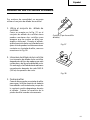
5. Beginning and ending the cutting operation:
As shown in Fig. 8, place the front base of the planer on the material and support the
planer horizontally. Turn ON the power switch, and slowly operate the planer toward the
leading edge of the material. Firmly depress the front half of the planer at the first stage
of cutting, as shown in Fig. 9, depress the rear half of the planer at the end of the cutting
operation. The planer must always be kept flat throughout the entire cutting operation.
6. Precaution after finishing the planing operation:
When the planer is suspended with one hand after finishing the planing operation, ensure
that the cutting blades (base) of the planer do not contact or come too near your body.
Failure to do so could result in serious injury.
Fig. 8 Beginning of cutting operation Fig. 9 End of cutting operation
(Depth of cut on soft wood is 0.5 mm)
Width of material Feed speed of body Length of cut
1-3/4" (45 mm) 33 ft/min (10 m/min) 100 ft (30 m)
2-3/8" (60 mm) 26 ft/min. (8 m/min) 72 ft (22 m)
3" (75 mm) 20 ft/min. (6 m/min) 50 ft (15 m)

English
18
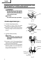
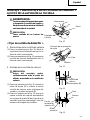
CARBIDE BLADE ASSEMBLY AND DISASSEMBLY AND
ADJUSTMENT OF CUTTER BLADE HEIGHT
WARNING:
Be absolutely sure to attach and de-
tach the planer blade and adjust its
height in a state where the battery is
removed from the unit.
CAUTION:
Be careful not to injure your hands.
< Double edged blade type >
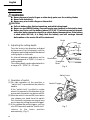
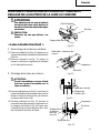
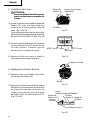
1. Carbide blade disassembly:
(1) As shown in Fig 10, loosen the blade
holder with the attached box wrench.
(2) As shown in Fig 11, remove the carbide
blade by sliding it with the attached box
wrench.
2. Carbide blade assembly:
CAUTION:
Prior to assembly, thoroughly wipe
off all swarf accumulated on the car-
bide blade.
(1) As shown in Fig. 12, lift set plate (B) and
insert the new carbide blade between
cutter block and set plate (B).
(2) As shown in Fig 13, mount the new carbide
blade by sliding it on the set plate (B) so
that the blade tip projects by 1mm from
the end of the cutter block.
Blade Holder
Bolt
Box Wrench
Fig. 10
Housing
Groove
Fig. 13
Groove
Back Metal
End of
Setplate (B)
Fig. 11
Fig. 12
Housing
Carbide Blade
Set Plate (B)
Carbide Blade

English
19
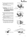
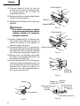
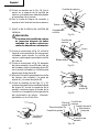
(3) As shown in Fig 14, fix the bolts at the
blade holder after blade replacement has
been completed.
(4) Turn the cutter block over, and set the
other side in the same manner.
3. Adjustment of carbide blade height:
CAUTION:
If the carbide blade’s heights are in-
accurate after above procedures have
been completed, carry out the proce-
dures described below.
(1) As shown in Fig 15, use the box wrench to
loosen the three bolts used to retain the
carbide blade, and remove the blade
holder.
(2) As shown in Fig 16, after removing the
carbide blade, slide set plate (B) in the
direction indicated by the arrow to
disassemble set plate (B).
(3) Loosen the 2 screws holding on the
carbide blade and set plate (A), set plate
(B).
(4) As shown in Fig 17, 18, press the turned
surface of set plate (A) to the wall surface
b while adjusting the carbide blade edge
to the wall surface a of the set gauge.
Then, tighten them with the 2 screws.
Box Wrench
Blade Holder
Bolt
Bolt
Blade Holder
Box Wrench
Fig. 14
Fig. 15
Set Plate (B)
Fig. 16
Machine Screw
Fig. 18
Wall Surface b
Fig. 17
Set Gauge
Turned Surface
Set Plate (A)
Set Plate (B)
Carbide Blade
Wall Surface a

English
20
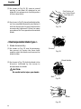
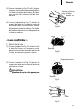
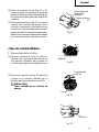
(5) As shown in Fig 19, 20, insert a turned
portion of set plate (A) attached to set
plate (B) into a groove on the flat portion
of the cutter block.
(6) As shown in Fig 21, place the blade holder
on the completed assembly and fasten it
with the three bolts. Ensure that the bolts
are securely tightened. Follow the same
procedures for the opposite side carbide
blade.
< Resharpenable blade type >
1. Blade disassembly:
(1) As shown in Fig. 15, use the accessory
box wrench to loosen the three bolts
used to retain the blade, and remove the
blade holder.
(2) As shown in Fig. 22, slide the blade in the
direction indicated by the arrow to
disassemble the blade.
CAUTION:
Be careful not to injure your hands.
Fig. 22
Set Plate (A)
Flat Portion of
the Cutter Block
Groove
Fig. 20
Fig. 21
Blade Holder
Bolt
Blade
Fig. 19
La page charge ...
La page charge ...
La page charge ...
La page charge ...
La page charge ...
La page charge ...
La page charge ...
La page charge ...
La page charge ...
La page charge ...
La page charge ...
La page charge ...
La page charge ...
La page charge ...
La page charge ...
La page charge ...
La page charge ...
La page charge ...
La page charge ...
La page charge ...
La page charge ...
La page charge ...
La page charge ...
La page charge ...
La page charge ...
La page charge ...
La page charge ...
La page charge ...
La page charge ...
La page charge ...
La page charge ...
La page charge ...
La page charge ...
La page charge ...
La page charge ...
La page charge ...
La page charge ...
La page charge ...
La page charge ...
La page charge ...
La page charge ...
La page charge ...
La page charge ...
La page charge ...
La page charge ...
La page charge ...
La page charge ...
La page charge ...
La page charge ...
La page charge ...
La page charge ...
La page charge ...
-
 1
1
-
 2
2
-
 3
3
-
 4
4
-
 5
5
-
 6
6
-
 7
7
-
 8
8
-
 9
9
-
 10
10
-
 11
11
-
 12
12
-
 13
13
-
 14
14
-
 15
15
-
 16
16
-
 17
17
-
 18
18
-
 19
19
-
 20
20
-
 21
21
-
 22
22
-
 23
23
-
 24
24
-
 25
25
-
 26
26
-
 27
27
-
 28
28
-
 29
29
-
 30
30
-
 31
31
-
 32
32
-
 33
33
-
 34
34
-
 35
35
-
 36
36
-
 37
37
-
 38
38
-
 39
39
-
 40
40
-
 41
41
-
 42
42
-
 43
43
-
 44
44
-
 45
45
-
 46
46
-
 47
47
-
 48
48
-
 49
49
-
 50
50
-
 51
51
-
 52
52
-
 53
53
-
 54
54
-
 55
55
-
 56
56
-
 57
57
-
 58
58
-
 59
59
-
 60
60
-
 61
61
-
 62
62
-
 63
63
-
 64
64
-
 65
65
-
 66
66
-
 67
67
-
 68
68
-
 69
69
-
 70
70
-
 71
71
-
 72
72


Hitachi P 20DA Instruction Manual And Safety Instructions
- Catégorie
- Outils électroportatifs
- Taper
- Instruction Manual And Safety Instructions
dans d''autres langues
- English: Hitachi P 20DA
- español: Hitachi P 20DA
Documents connexes
-
Hitachi P 20SF Instruction Manual And Safety Instructions
-
Hitachi P 20SB Manuel utilisateur
-
-
-
-
-
-
-
Hitachi P18DSL Manuel utilisateur
-
Hitachi F-30A Manuel utilisateur
