
BelAir20EO and AP 511x Series Quick
Install Guide
QUICK GUIDE
1/006 92-LZA 101 803 Uen D

Copyright
© Ericsson AB 2013. All rights reserved. No part of this document may be
reproduced in any form without the written permission of the copyright owner.
Disclaimer
The contents of this document are subject to revision without notice due to
continued progress in methodology, design and manufacturing. Ericsson shall
have no liability for any error or damage of any kind resulting from the use
of this document.
Trademark List
Wi-Fi
®
Wi-Fi
®
is a registered trademark of the Wi-Fi Alliance.
Wi-Fi Certified Logo
The Wi-Fi CERTIFIED logo is a registered trademark
of the Wi-Fi Alliance.
Ericsson
Ericsson is the trademark or registered trademark of
Telefonaktiebolaget LM Ericsson. All other product or
service names mentioned in this manual are trademarks
of their respective companies.
1/006 92-LZA 101 803 Uen D | 2013-12-13

Getting Started
1 Getting Started
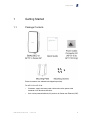
1.1 Package Contents
External antennas are ordered and shipped separately.
For AP 5115 to AP 5118:
• Customers supply their own power cable and use the power cable
connector kit to terminate the cable.
• Units can be powered either by AC power or by Power over Ethernet (PoE).
2
1/006 92-LZA 101 803 Uen D | 2013-12-13

BelAir20EO and AP 511x Series Quick Install Guide
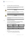
1.2 AC Power (AP 5115 to AP 5118 Only)
These units accept AC input power in the range of 100–240 V AC. The units do
not have a power switch. They are powered on when connected to a power
source. Maximum AC power consumption is 14.5 W.
Warning!
The unit contains a 5-A fuse and relies on the rated fuse or circuit breaker of
the wall outlet (15 A in North America, 10 A in Europe).
Warning!
Use ONLY the Ericsson power cable connector supplied with the unit. Use of
any other power cable connector can damage the unit and voids the Ericsson
product warranty.
1.3 Internet Port and Power
The unit can be powered with IEEE 802.3af or IEEE 802.3at Power over
Ethernet (PoE). Use IEEE 802.3af PoE for most applications. IEEE 802.3af
PoE supplies a maximum of 12.95 W to the powered device.
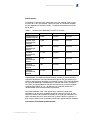
Table 1 PoE Power Consumption Table
State PoE Port Only
PoE Port and One LAN
Port
Idle 3.6 W 4.05 W
Medium Traffic 8.4 W 8.85 W
High Traffic 10.8 W 11.25 W
Max. Traffic 11.76 W 12.21 W
The PoE switch or power injector must meet local and national regulatory
requirements.
802.3at Power Source Equipment (PSE) Specification:
• 50.0 to 57 V DC, with 30 W output power from the PSE
3
1/006 92-LZA 101 803 Uen D | 2013-12-13

Getting Started
802.3at Powered Device (PD) Specification:
• 42.5 to 57 V DC at the PD, with 25.5 W maximum input power to the PD
802.3at Cable Specification:
• 100 m maximum length
• Maximum cable pair resistance of 12.5 Ohms, satisfied by using CAT5
or CAT5e as specified by ANSI/TIA/EIA-568 or Class D as specified by
ISO/IEC 11801:1995
• 600 mA maximum current per pair
1.4 Functional Earth Ground and Lightning Protection
Units are not designed to survive a direct lightning hit. However, they are
intended to withstand the voltage and current surges induced from nearby
lightning activity.
The level of required lightning protection depends on regional lightning
conditions and location of installation. For example, an AP installed on a roof
top requires greater lightning protection than an AP installed on the side of a
building. The following is a list of recommended installation practices to mitigate
the voltage and current surges induced from lightning activity. If there is a
conflict between these recommendations and local or national electrical codes,
the local or national electrical codes must be followed.
• For streetlight or hydro/telecom pole mounting the AC power adapter
should be protected with a lightning surge protector. AC power routed to
the power adapter must be routed inside the pole. If power is routed on the
pole exterior, the power must be routed through a metal conduit grounded
at the base of the pole.
• For rooftop installations, the unit must not be mounted at the highest point
on the building. If the building has installed lightning arrestors, the unit must
be located within the umbrella protection zone—a 60 degree zone under
the lighting arrestor, but if possible, the unit should not be located closer
than 30 feet (approx. 10 m) from the lightning arrestor. Power and Ethernet
cables must be routed through independent grounded metal conduits.
• For lightning surge protection, the installer must connect a separate ground
wire between the external chassis of the unit and a ground on the pole. The
ground point on the AP accepts a
1
/4” screw.
• It is recommended for areas susceptible to lightning activity, such as on
poles, rooftops, or on or near any tall structures, that shielded CAT 5e or
CAT 6 Ethernet cable be employed.
• The external antennas ports of the unit require lightning arrestors to be
employed whenever the external antenna is located more than 3 feet
4
1/006 92-LZA 101 803 Uen D | 2013-12-13

BelAir20EO and AP 511x Series Quick Install Guide
(approx. 1 m) from the unit. When lightning arrestors are used, they must
be located within 3 feet (approx. 1 m) of the unit and must be grounded
to both the unit and protective earth ground. The
1
/4” GND screw of the
unit can be used for this application.
5
1/006 92-LZA 101 803 Uen D | 2013-12-13

Installing the BelAir20EO and AP 511x Series AP
2 Installing the BelAir20EO and AP 511x
Series AP
2.1 Step 1—Select Location
Choose a proper place for the unit. In general, the best location is at the
center of the intended wireless coverage area, within line of sight of all wireless
devices. For optimum performance, consider these guidelines:
• Mount the unit as high as possible above any obstructions in the coverage
area.
• Avoid mounting next to or near building support columns or other
obstructions that can cause reduced signal or null zones in parts of the
coverage area.
• Mount away from any signal absorbing or reflecting structures (such as
those containing metal).
The unit can be mounted on any wall or on a pole.
Warning!
Do not install the unit in any areas where blasting (blasting caps, radio
controlled equipment) or explosive gases can be present.
Warning!
To comply with FCC radio frequency (RF) exposure limits (FCC OET 65C) for
the general population, antennas must be located a minimum distance of 12
inches (approx. 30 cm) or more from the body of all persons.
61/006 92-LZA 101 803 Uen D | 2013-12-13

BelAir20EO and AP 511x Series Quick Install Guide
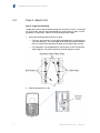
2.2 Step 2—Mount Unit
Wall or Large Pole Mounting
Large poles have an outer diameter greater than 3 inches (7.6 cms). If mounted
on a flat surface, the unit must be mounted to a surface that is at least 1/2-inch
plywood or its equivalent. Poles must have the equivalent rigidity.
1. Attach the mounting plate to the wall or pole.
• For walls, use up to four 1/4 inch (M6) anchoring bolts. Use the plate as
a drill hole template. The outer edges of the plate must be elevated from
the wall surface while the center channel must touch the wall surface.
• For large poles, use through bolts or use the pairs of slots for stainless
steel strapping. The center channel must touch the pole surface.
2. Connect ground wire to unit.
7 1/006 92-LZA 101 803 Uen D | 2013-12-13

Installing the BelAir20EO and AP 511x Series AP
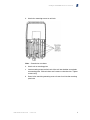
3. Attach four mounting screws to unit back.
Note: Ground wire not shown.
4. Attach unit to mounting plate:
a Insert mounting screws on the back of the unit into shoulder screw holes
on mounting plate. Slide unit down until screws are into the slots. Tighten
screws snug.
b Screw in the remaining mounting screw at base of unit into the mounting
plate hole.
8
1/006 92-LZA 101 803 Uen D | 2013-12-13

BelAir20EO and AP 511x Series Quick Install Guide
Note: Ground wire not shown.
Small Pole Mounting
Small poles have an outer diameter less than 3 inches (7.6 cms).
1. Connect ground wire to unit.
2. Use two stainless steel straps to secure unit to pole.
9
1/006 92-LZA 101 803 Uen D | 2013-12-13

Installing the BelAir20EO and AP 511x Series AP
Note: Ground wire not shown. Strap mounting applies to all units except
the AP 5115 to AP 5118.
2.3 Step 3—Mount and Attach External Antennas
This step applies only to the following APs:
Table 2 APs and Required Antennas
APs
Required
Antennas
Ericsson Description
and Part Number
BelAir20EO-11C,
BelAir20EO-11CR2,
AP 5117R, AP 5117U
Two 5 GHz
External 11.5 dBi
5 GHz 11.5 dBi Dual
Feed Directional Antenna
(BNCKH0091 or INE 105
2162)
BelAir20EO-11D,
BelAir20EO-11DR2,
AP 5118R, AP 5118U
Two 2.4 GHz
External 8 dBi
2.4 GHz 8 dBi Dual
Feed Directional Antenna
(BNCKH0007 or INE 105
2159)
AP 5113 One 2.4 GHz
External 12 dBi
Dual Polarization 2.4–2.5
GHz Flat Panel Antenna
12 dBi (KRE 105 217)
Mounting Kit (KRY 901
293)
The external antennas must be approved by Ericsson specifically for the APs.
The antennas are ordered and shipped separately.
1. Attach the 5 GHz or 2.4 GHz antennas to their mounting surface.
Ericsson provides several different types of 5 GHz and 2.4 GHz antennas,
each with its own requirements and procedures for attaching to a mounting
surface. For details on attaching the antennas to their mounting surface,
10
1/006 92-LZA 101 803 Uen D | 2013-12-13

BelAir20EO and AP 511x Series Quick Install Guide
refer to the mounting procedures supplied with the antennas that were
ordered.
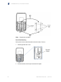
2. Connect external 5 GHz or 2.4 GHz antennas to connectors. See the
figure. Connect only antennas that are approved specifically for the units.
Either antenna can connect to either connector. Use thread-locker and
self-amalgamating tape to keep connection tight and waterproof.
• Connect external 5 GHz or 2.4 GHz antennas here.
• Connect only antennas that are approved specifically for the units.
• Either antenna can connect to either connector.
• Use thread-locker and self-amalgamating tape to keep connection tight
and waterproof.
Note: Ground wire and mounting hardware not shown.
2.4 Step 4—Prepare Power Cable (AP 5115 to AP 5118
Only)
Refer to Figure 1.
11
1/006 92-LZA 101 803 Uen D | 2013-12-13

Installing the BelAir20EO and AP 511x Series AP
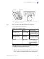
Figure 1 Power Cable Connector Assembly
1. Place compression nut (4), grommet (3), and body (2) over power cable
as shown in Figure 1.
2. Strip outer jacket and inner conductors as shown in Figure 1.
3. Secure conductors to appropriate terminals by tightening screws on insert
assembly (1). Refer to the following table.
Conductor
Type
North American
Color
European Color
Terminal ID
Ground Green/Yellow Green/Yellow
1
Power Black Brown
2
Neutral White Blue
3
4. Attach body (2) to insert assembly (1) by rotating black knurled ring on
insert assembly in a clockwise direction.
5. Secure compression nut (4) to body (2) by rotating in a clockwise direction.
12
1/006 92-LZA 101 803 Uen D | 2013-12-13

BelAir20EO and AP 511x Series Quick Install Guide
2.5 Step 5—Connect and Power On
BelAir20EO and All AP 511x Series: Power over Ethernet
The AP gets its operating power from the PoE port when connected to a device
that provides IEEE 802.3af or 802.3at compliant Power over Ethernet (PoE).
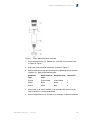
Figure 2 Power Connection for BelAir20EO and All AP 511x Series Power
over Ethernet
Note: Ground wire and mounting hardware not shown.
Warning!
The BelAir20EO and AP 511x series AP must be connected to a power source
that complies to IEEE 802.3af or 802.3at.
Caution!
The PoE connection to the BelAir20EO and AP 511x series AP must use the
supplied Ethernet gland to ensure a waterproof connection. Failure to use the
Ethernet gland voids the Ericsson product warranty.
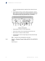
AP 5115 to AP 5118 Only
The AP can get its operating power directly from an AC power source or from
the Internet port when connected to a device that provides IEEE 802.3af or
802.3at compliant Power over Ethernet (PoE). If the AP is connected to both a
PoE source device and an AC power source, the AP automatically adjusts to
use the most suitable power source.
13
1/006 92-LZA 101 803 Uen D | 2013-12-13

Installing the BelAir20EO and AP 511x Series AP
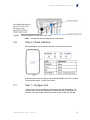
Figure 3 Power Connections for AP 5115 to AP 5118
Note: Ground wire and mounting hardware not shown.
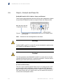
2.6 Step 6—Check Indicators
After powering on, wait 2 minutes and check the indicators on the unit.
If the indicators are not as shown, refer to the BelAir20EO and AP 511x Series
Technical Description, 1/1550-LZA 101 803.
2.7 Step 7—Configure Unit
In most cases, the unit configures itself automatically after powering on. To
configure the unit manually through its local web interface or Command Line
Interface (CLI), refer to the Access Point User Guide, 1/1553-LZA 101 806.
14
1/006 92-LZA 101 803 Uen D | 2013-12-13

BelAir20EO and AP 511x Series Quick Install Guide
© Ericsson AB 2013. All rights reserved. No part of this
document may be reproduced in any form without the written
permission of the copyright owner.
The contents of this document are subject to revision without
notice due to continued progress in methodology, design and
manufacturing. Ericsson shall have no liability for any error or
damage of any kind resulting from the use of this document.
1/006 92-LZA 101 803 Uen D

BelAir20EO and AP 511x Series Conformity
and Regulatory Statements
STATEMENT OF COMPLIANCE
1/174 02-LZA 101 803 Uen C

Copyright
© Ericsson AB 2013. All rights reserved. No part of this document may be
reproduced in any form without the written permission of the copyright owner.
Disclaimer
The contents of this document are subject to revision without notice due to
continued progress in methodology, design and manufacturing. Ericsson shall
have no liability for any error or damage of any kind resulting from the use
of this document.
Trademark List
Wi-Fi
®
Wi-Fi
®
is a registered trademark of the Wi-Fi Alliance.
Wi-Fi Certified Logo
The Wi-Fi CERTIFIED logo is a registered trademark
of the Wi-Fi Alliance.
Ericsson
Ericsson is the trademark or registered trademark of
Telefonaktiebolaget LM Ericsson. All other product or
service names mentioned in this manual are trademarks
of their respective companies.
1/174 02-LZA 101 803 Uen C | 2013-12-13

Contents
Contents
1 About this Document 1
1.1 Scope 1
1.2 Target Group 1
1.3 Comments About the Documentation 1
2 Regulatory Information and Disclaimers 2
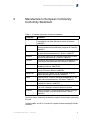
3 Manufacturer’s US Federal Communication
Commission Conformity Statement 3
3.1 FCC Interference Statement 3
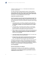
4 Manufacturer’s Industry Canada Conformity Statement 5
5 Manufacturer’s European Community Conformity
Statement 9
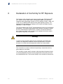
6 Declaration of Conformity for RF Exposure 12
7 Product Disposal 13
7.1 Mise au rebut du produit 13
7.2 Produktentsorgung 13
7.3 Verwijdering van het product 13
7.4 Tuotteen hävittäminen 14
7.5 Smaltimento del prodotto 14
7.6 Produktbortskaffelse 14
7.7 Eliminação do produto 14
7.8 Eliminación del producto 14
1/174 02-LZA 101 803 Uen C | 2013-12-13

BelAir20EO and AP 511x Series Conformity and Regulatory Statements
1/174 02-LZA 101 803 Uen C | 2013-12-13
La page est en cours de chargement...
La page est en cours de chargement...
La page est en cours de chargement...
La page est en cours de chargement...
La page est en cours de chargement...
La page est en cours de chargement...
La page est en cours de chargement...
La page est en cours de chargement...
La page est en cours de chargement...
La page est en cours de chargement...
La page est en cours de chargement...
La page est en cours de chargement...
La page est en cours de chargement...
La page est en cours de chargement...
La page est en cours de chargement...
-
 1
1
-
 2
2
-
 3
3
-
 4
4
-
 5
5
-
 6
6
-
 7
7
-
 8
8
-
 9
9
-
 10
10
-
 11
11
-
 12
12
-
 13
13
-
 14
14
-
 15
15
-
 16
16
-
 17
17
-
 18
18
-
 19
19
-
 20
20
-
 21
21
-
 22
22
-
 23
23
-
 24
24
-
 25
25
-
 26
26
-
 27
27
-
 28
28
-
 29
29
-
 30
30
-
 31
31
-
 32
32
-
 33
33
-
 34
34
-
 35
35


dans d''autres langues
- English: Ericsson AP 5118U User manual
Documents connexes
Autres documents
-
 Miniso EBS-1005 Wireless Soundbar Manuel utilisateur
-
Schlage Lock COMAD400V3 Manuel utilisateur
-
Aerohive AP370 Manuel utilisateur
-
 enlighted GW-2-01 Guide d'installation
-
YUNEEC 2ACS5-ST12 Manuel utilisateur
-
Assa Abloy AYR-MOD-MT1-USA Matter Smart Module Mode d'emploi
-
TP-LINK WBS510 Guide d'installation
-
Elster A4MGK4A Manuel utilisateur
-
Sony Ericsson MD400G Manuel utilisateur
-
Cisco C9117AXI-x Getting Started Manual

