
Page 1 of 4
IMPORTANT! Read all instructions before installing and using. Installer: This manual must be delivered to the end user.
Important! This unit is a safety device, and it must be connected to its own separate, fused power point to assure its continued operation should any other
electrical accessory fail.
Installation and Operation Instructions
HB12PAK SERIES
1. Proper installation combined with operator training in the use, care, and maintenance of emergency warning devices are essential to ensure
the safety of you and those you are seeking to protect.
2. Exercise caution when working with live electrical connections.
3. This product must be properly grounded. Inadequate grounding and/or shorting of electrical connections can cause high current arcing,
which can cause personal injury and/or severe vehicle damage, including re.
4. Proper placement and installation are vital to the performance of this warning device. Install this product so that output performance of the
system is maximized and the controls are placed within convenient reach of the operator so that s/he can operate the system without losing
eye contact with the roadway.
5. Do not install this product or route any wires in the deployment area of an air bag. Equipment mounted or located in an air bag deployment
area may reduce the eectiveness of the air bag or become a projectile that could cause serious personal injury or death. Refer to the
vehicle owner’s manual for the air bag deployment area. It is the responsibility of the user/operator to determine a suitable mounting location
ensuring the safety of all passengers inside the vehicle particularly avoiding areas of potential head impact.
6. It is the responsibility of the vehicle operator to ensure during use that all features of this product work correctly. In use, the vehicle operator
should ensure the projection of the warning signal is not blocked by vehicle components (i.e., open trunks or compartment doors), people,
vehicles or other obstructions.
7. The use of this or any other warning device does not ensure all drivers can or will observe or react to a warning signal. Never take the right-
of-way for granted. It is your responsibility to be sure you can proceed safely before entering an intersection, driving against trac, respond-
ing at a high rate of speed, or walking on or around trac lanes.
8. This equipment is intended for use by authorized personnel only. The user is responsible for understanding and obeying all laws regarding
warning signal devices. Therefore, the user should check all applicable city, state, and federal laws and regulations. The manufacturer as-
sumes no liability for any loss resulting from the use of this warning device.
Do not install and/or operate this safety product unless you have read and understand the safety information
contained
Failure to install or use this product according to manufacturers recommendations may result in property damage, serious injury, and/or death to
those you are seeking to protect!
!
WARNING!
Size: 0.99” dia. (lighthead only)
Input Voltage: 12-24 VDC
Maximum Current Draw:
Single Color:
1.06 A (Red, steady on)
1.24 A (Blue, steady on)
1.30 A (Amber, steady on)
1.27 A (White, steady on)
Dual Color:
0.61 A (AW, Amber steady on)
0.81 A (AW, White steady on)
0.59 A (BR, Red steady on & Blue
steady on)
Specications:
Maximum Power:
Single Color:
13.57 W (Red, steady on)
15.87 W (Blue, steady on)
16.64 W (Amber, steady on)
16.26 W (White, steady on)
Dual Color:
7.81 W (AW, Amber steady on)
10.37 W (AW, White steady on)
7.55 W (BR, Red steady on & Blue steady on)
Operating Temperature Range: -40° to 70°C
Lumens:
Dual Amber - 130 lm
Dual Blue - 39.1 lm
Dual Red - 64.5 lm
Dual White - 99.7 lm
Single Amber - 226.2 lm
Single Blue - 49.4 lm
Single Red - 84.32 lm
Single White - 209.8 lm

Page 2 of 4
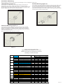
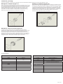
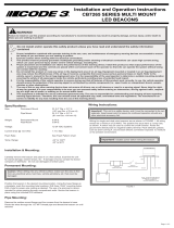
Twist-lock Mounting (Figure 3):
Locate and removed the OEM light bulb plug by rotating it counter clockwise
until the bulb plug stops in its rotation, pull out of the socket. Take note of the
positions of the retention cam clearance notches. Apply silicone RTV sealant
around the rubber gasket. Insert the twist-lock lighthead through the socket and
rotate it clockwise until it stops.
Make sure lighthead is tightly secured in the socket.
Figure 3
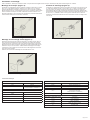
Lamp Mounting (Figure 1):
Pick a location in the vehicle lamp housing that is at least 1” away from any
Install the LED head into the hole as shown in Figure 1. Use silicone RTV around
the LED head to seal. Strap the driver module to a nearby wire harness or body
structure. Make electrical connections as described below.
Surface Mounting (Figure 2):
Pick a location in the vehicle body that is at least 1” away from other objects. Drill
a 1” hole in the body with a hole saw. Using the bezel as a template, mark and
drill the mounting hole locations in the mounting surface. Make the electrical
connections described below and place the LED head in the 1” hole. Install the
bezel and bracket using the two screws provided. Silicone RTV sealant should be
used around the mounting and screw holes.
Figure 1
Figure 2
Installation & Mounting:
Before installation, examine the LED heads for transit damage. Do not use damaged or broken parts.
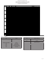
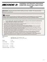
Single Color Flash Pattern Chart
Tabla de patrones de parpadeo de color único
Tableau des modes de clignotements unicolores
Einfarbige Leuchtmustertabelle
RED AMBER BLUE WHITE RED AMBER BLUE RED AMBER BLUE
1
Single Flash 75FPM sim. Phase1
YES
Class 2 Class 2 Class 2 Class 2
Class B Class B Class B N/C N/C N/C
2
Single Flash 75FPM sim. Phase2
YES
Class 2 Class 2 Class 2 Class 2
Class B Class B Class B N/C N/C N/C
3
Single Flash 75FPM Alt.
YES
N/C N/C N/C N/C
N/C N/C N/C N/C N/C N/C
4
Single Flash 120FPM sim. Phase1
YES
Class 2 Class 2 Class 2 Class 2
N/C N/C N/C Class 1 Class 1 Class 1
5
Single Flash 120FPM sim. phase2
YES
Class 2 Class 2 Class 2 Class 2
N/C N/C N/C Class 1 Class 1 Class 1
6
Single Flash 120FPM Alt.
YES
N/C N/C N/C N/C
N/C N/C N/C N/C N/C N/C
7
Double Fl
ash 75FPM sim. Phase1
YES
Class 2 Class 2 Class 2 Class 2
N/C N/C N/C N/C N/C N/C
8
Double Flash 75FPM sim. phase2
YES
Class 2 Class 2 Class 2 Class 2
N/C N/C N/C N/C N/C N/C
9
Double Flash 75FPM Alt.
YES
N/C N/C N/C N/C
N/C N/C N/C N/C N/C N/C
10
Double Flash 120FPM sim. Phase1
YES
Class 2 Class 2 Class 2 Class 2
N/C N/C N/C Class 1 Class 1 Class 1
11
Double Flash 120FPM sim. phase2
YES
Class 2 Class 2 Class 2 Class 2
N/C N/C N/C Class 1 Class 1 Class 1
12
Double Flash 120FPM Alt.
YES
N/C N/C N/C N/C
N/C N/C N/C N/C N/C N/C
13-Default
Quad Flash 75FPM sim. Ph
ase1
YES
Class 2 Class 2 Class 2 Class 2
N/C N/C N/C N/C N/C N/C
14
Quad Flash 75FPM sim. Phase2
YES
Class 2 Class 2 Class 2 Class 2
N/C N/C N/C N/C N/C N/C
15
Quad Flash 75FPM Alt.
YES
N/C N/C N/C N/C
N/C N/C N/C N/C N/C N/C
16
Quad Flash 150FPM sim. Phase1
YES
Class 2 Class 2 Class 2 Class 2
N/C N/C N/C N/C N/C N/C
17
Quad Flash 150FPM sim. Phase2
YES
Class 2 Class 2 Class 2 Class 2
N/C N/C N/C N/C N/C N/C
18
Quad Flash 150FPM Alt
YES
N/C N/C N/C N/C
N/C N/C N/C N/C N/C N/C
19
Triple 75FPM sim. Phase1
YES
Class 2 Class 2 Class 2 Class 2
N/C N/C N/C N/C N/C N/C
20
Triple 75FPM sim. Phase2
YES
Class 2 Class 2 Class 2 Class 2
N/C N/C N/C N/C N/C N/C
21
Triple 75FPM Alt.
YES
N/C N/C N/C N/C
N/C N/C N/C N/C N/C N/C
22
Quint Flash 150FPM sim. Phase1
YES
Class 2 Class 2 Class 2 Class 2
N/C N/C N/C N/C N/C N/C
23
Quint Flash 150FPM sim. Phase2
YES
Class 2 Class 2 Class 2 Class 2
N/C N/C N/C N/C N/C N/C
24
Quint Flash 150FPM Alt.
YES
N/C N/C N/C N/C
N/C N/C N/C N/C N/C N/C
9
25
Steady - Single NO N/C N/C N/C N/C
N/C N/C N/C N/C N/C N/C
10
26
Steady Burn NO N/C N/C N/C N/C
N/C N/C N/C N/C N/C N/C
11
27
Modulation NO N/C N/
C N/C N/C
N/C N/C N/C N/C N/C N/C
12
28
2 Double Flash,2 Triple Alt. NO N/C N/C N/C N/C
N/C N/C N/C N/C N/C N/C
13
29
4 Single Flash ,2 Quad Flash Alt. NO N/C N/C N/C N/C
N/C N/C N/C N/C N/C N/C
6
7
8
Pattern
MODE
PATTERNS
SYNC.
SAE J595
CA T13 ECE R65
1
2
3
4
5

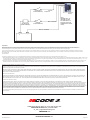
Electrical Connections:
SINGLE COLOR
RED POSITIVE
BLACK NEGATIVE
BLUE
PATTERN SELECT TO NEGATIVE / DIM TO
POSITVE (ON WARNING PATTERN ONLY)
YELLOW SYNCHRONIZED FUNCTION
APPLY BLUE TO BLACK WIRE FUNCTION
0-1 SEC. NEXT PATTERN
1-3 SEC. PREVIOUS PATTERN
3-5 SEC. FACTORY DEFAULT PATTERN
5 SEC. LAST PATTERN
DUAL COLOR
RED POSITIVE, COLORS 1 & 3
WHITE POSITIVE, COLORS 2 & 4
RED & WHITE POSITIVE, (COLORS 1 & 3) & (COLORS 2 & 4)
BLACK NEGATIVE
BLUE
PATTERN SELECT TO NEGATIVE / DIM TO POSITIVE (ON
WARNING PATTERN ONLY)
YELLOW SYNCHRONIZED FUNCTION
APPLY BLUE TO BLACK WIRE FUNCTION
0-1 SEC. NEXT PATTERN
1-3 SEC. PREVIOUS PATTERN
3-5 SEC. FACTORY DEFAULT PATTERN
5 SEC. LAST PATTERN
Page 3 of 4
Dual Color Flash Pattern Chart
Tabla de patrones de parpadeo de color doble
Tableau des modes de clignotements bicolore
Zweifarbig Leuchtmustertabelle
RED AMBER BLUE WHITE RED AMBER BLUE RED AMBER BLUE
1-Default 1 SAE/T13 SAE/T13 Single 75FPM Ph1 Color 1 Synchronous Color 3
YES Class 2 Class 2 Class 2 Class 2 Class B Class B Class B N/C N/C N/C
2 2 SAE/T13 SAE/T13 Single 75FPM Ph2 Color 1 Synchronous Color 3
YES Class 2 Class 2 Class 2 Class 2 Class B Class B Class B N/C N/C N/C
3 SAE/T13 Single 75FPM Ph1 Color 1 Alternately Color 4
YES N/C N/C N/C N/C N/C N/C N/C N/C N/C N/C
4 SAE/T13 Single 75FPM Ph2 Color 1 Alternately Color 4
YES N/C N/C N/C N/C N/C N/C N/C N/C N/C N/C
1-Default 5 SAE/T13 Single 75FPM Ph1 Color 2 Synchronous Color 4
YES Class 2 Class 2 Class 2 Class 2 Class B Class B Class B N/C N/C N/C
2 6 SAE/T13 Single 75FPM Ph2 Color 2 Synchronous Color 4
YES Class 2 Class 2 Class 2 Class 2 Class B Class B Class B N/C N/C N/C
3 3 7 SAE/T13 Single 75FPM Ph1(Color 1 Synchronous Color 3) Alternately (Color 2 Synchronous Color 4)
YES N/C N/C N/C N/C N/C N/C N/C N/C N/C N/C
4 4 8 SAE/T13 Single 75FPM Ph2(Color 1 Synchronous Color 3) Alternately (Color 2 Synchronous Color 4)
YES N/C N/C N/C N/C N/C N/C N/C N/C N/C N/C
5 5 9 SAE/T13 Single 75FPM (Color 1 Alternately Color 2) Alternately (Color 3 Alternately Color 4)
YES N/C N/C N/C N/C N/C N/C N/C N/C N/C N/C
6 10 Single 375FPMFPM Ph1 Color 1 Synchronous Color 3
YES N/C N/C N/C N/C N/C N/C N/C N/C N/C N/C
7 11 Single 375FPMFPM Ph2 Color 1 Synchronous Color 3
YES N/C N/C N/C N/C N/C N/C N/C N/C N/C N/C
12 Single 375FPMFPM Ph1 Color 1 Alternately Color 4
YES N/C N/C N/C N/C N/C N/C N/C N/C N/C N/C
13 Single 375FPMFPM Ph2 Color 1 Alternately Color 4
YES N/C N/C N/C N/C N/C N/C N/C N/C N/C N/C
6 14 Single 375FPMFPM Ph1 Color 2 Synchronous Color 4
YES N/C N/C N/C N/C N/C N/C N/C N/C N/C N/C
7 15 Single 375FPMFPM Ph2 Color 2 Synchronous Color 4
YES N/C N/C N/C N/C N/C N/C N/C N/C N/C N/C
8 8 16 Single 375FPMFPM Ph1 (Color 1 Synchronous Color 3) Alternately (Color 2 Synchronous Color 4)
YES N/C N/C N/C N/C N/C N/C N/C N/C N/C N/C
9 9 17 Single 375FPMFPM Ph2 (Color 1 Synchronous Color 3) Alternately (Color 2 Synchronous Color 4)
YES N/C N/C N/C N/C N/C N/C N/C N/C N/C N/C
10 10 18 Single 375FPMFPM (Color 1 Alternately Color 2) Alternately (Color 3 Alternately Color 4)
YES N/C N/C N/C N/C N/C N/C N/C N/C N/C N/C
11
19 SAE/T13 Double 75
FPM Ph1 Color 1 Synchronous Color 3
YES Class 2 Class 2 Class 2 Class 2 N/C N/C N/C N/C N/C N/C
12
20 SAE/T13 Double 75FPM Ph2 Color 1 Synchronous Color 3
YES Class 2 Class 2 Class 2 Class 2 N/C N/C N/C N/C N/C N/C
21 SAE/T13 Double 75FPM Ph1 Color 1 Alternately Color 4
YES N/C N/C N/C N/C N/C N/C N/C N/C N/C N/C
22 SAE/T13 Double 75FPM Ph2 Color 1 Alternately Color 4
YES N/C N/C N/C N/C N/C N/C N/C N/C N/C N/C
11
23 SAE/T13 Double 75FPM Ph1 Color 2 Synchronous Color 4
YES Class 2 Class 2 Class 2 Class 2 N/C N/C N/C N/C N/C N/C
12
24 SAE/T13 Double 75FPM Ph2 Color 2 Synchronous Color 4
YES Class 2 Class 2 Class 2 Class 2 N/C N/C N/C N/C N/C N/C
13 13
25 SAE/T13 Double 75FPM Ph1 (Color 1 Synchronous Color 3) Alternately (C
olor 2 Synchronous Color 4)
YES N/C N/C N/C N/C N/C N/C N/C N/C N/C N/C
14 14
26 SAE/T13 Double 75FPM Ph2 (Color 1 Synchronous Color 3) Alternately (Color 2 Synchronous Color 4)
YES N/C N/C N/C N/C N/C N/C N/C N/C N/C N/C
15 15
27 SAE/T13 Double 75FPM (Color 1 Alternately Color 2) Alternately (Color 3 Alternately Color 4)
YES N/C N/C N/C N/C N/C N/C N/C N/C N/C N/C
16 28 ECER65/SAE Double 120FPM Ph1 Color 1 Synchronous Color 3
YES Class 2 Class 2 Class 2 Class 2 N/C N/C N/C Class 1 Class 1 Class 1
17 29 ECER65/SAE Double 120FPM Ph2 Color 1 Synchronous Color 3
YES Class 2 Class 2 Class 2 Class 2 N/C N/C N/C Class 1 Class 1 Class 1
30 ECER65/SAE Double 120FPM Ph1 Color 1 Alternately Color 4
YES N/C N/C N/C N/C N/C N/C N/C N/C N/C N/C
31 ECER65/SAE Double 120FPM Ph2 Color 1 Alternately Color 4
YES N/C N/C N/C N/C N/C N/C N/C N/C N/C N/C
16 32 ECER65/SAE Double 120FPM Ph1 Color 2 Synchronous Color 4
YES Class 2 Class 2 Class 2 Class 2 N/C N/C N/C Class 1 Class 1 Class 1
17 33 ECER65/SAE Double 120FPM Ph2 Color 2 Synchronous Color 4
YES Class 2 Class 2 Class 2 Class 2 N/C N/C N/C Class 1 Class 1 Class 1
18 18 34 ECER65/SAE Double 120FPM Ph1 (Color 1 Synchronous Color 3) Alternately (Color 2 Synchronous Color 4)
YES N/C N/C N/C N/C N/C N/C N/C N/C N/C N/C
19 19 35 ECER65/SAE Double 120FPM Ph2 (Color 1 Synchronous Color 3) Alternately (Color 2 Synchronous Color 4)
YES N/C N/C N/C N/C N/C N/C N/C N/C N/C N/C
20 20 36 ECER65/SAE Double 120FPM (Color 1 Alternately Color 2) Alternately (Color 3 Alternately Color 4)
YES N/C N/C N/C N/C N/C N/C N/C N/C N/C N/C
21 37 SAE/T13 Triple 75FPM Ph1 Color 1 Synchronous Color 3
YES Class 2 Class 2 Class 2 Class 2 N/C N/C N/C N/C N/C N/C
22 38 SAE/T13 Triple 75FPM Ph2 Color 1 Synchronous Color 3
YES Class 2 Class 2 Class 2 Class 2 N/C N/C N/C N/C N/C N/C
39 SAE/T13 Triple 75FPM Ph1 Color 1 Alternately Color 4
YES N/C N/C N/C N/C N/C N/C N/C N/C N/C N/C
40 SAE/T13 Triple 75FPM Ph2 Color 1 Alternately Color 4
YES N/C N/C N/C N/C N/C N/C N/C N/C N/C N/C
21 41 SAE/T13 Triple 75FPM Ph1 Color 2 Synchronous Color 4
YES Class 2 Class 2 Class 2 Class 2 N/C N/C N/C N/C N/C N/C
22 42 SAE/T13 Triple 75FPM Ph2 Color 2 Synchronous Color 4
YES Class 2 Class 2 Class 2 Class 2 N/C N/C N/C N/C N/C N/C
23 23 43 SAE/T13 Triple 75FPM Ph1 (Color 1 Synchronous Color 3) Alternately (Color 2 Synchronous Color 4)
YES N/C N/C N/C N/C N/C N/C N/C N/C N/C N/C
24 24 44 SAE/T13 Triple 75FPM Ph2 (Color 1 Synchronous Color 3) Alternately (Color 2 Synchronous Color 4)
YES N/C N/C N/C N/C N/C N/C N/C N/C N/C N/C
25 25 45 SAE/T13 Triple 75FPM (Color 1 Alternately Color 2) Alternately (Color 3 Alternately Color 4)
YES N/C N/C N/C N/C N/C N/C N/C N/C N/C N/C
26 46 SAE/T13 Quad 75FPM Ph1 Color 1 Synchronous Color 3
YES Class 2 Class 2 Class 2 Class 2 N/C N/C N/C N/C N/C N/C
27 47 SAE/T13 Quad 75FPM Ph2 Color 1 Synchronous Color 3
YES Class 2 Class 2 Class 2 Class 2 N/C N/C N/C N/C N/C N/C
48 SAE/T13 Quad 75FPM Ph1 Color 1 Alternately Color 4
YES N/C N/C N/C N/C N/C N/C N/C N/C N/C N/C
49 SAE/T13 Quad 75FPM Ph2 Color 1 Alternately Color 4
YES N/C N/C N/C N/C N/C N/C N/C N/C N/C N/C
26 50 SAE/T13 Quad 75FPM Ph1 Color 2 Synchronous Color 4
YES Class 2 Class 2 Class 2 Class 2 N/C N/C N/C N/C N/C N/C
27 51 SAE/T13 Quad 75FPM Ph2 Color 2 Synchronous Color 4
YES Class 2 Class 2 Class 2 Class 2 N/C N/C N/C N/C N/C N/C
28 28 52-Default SAE/T13 Quad 75FPM Ph1 (Color 1 Synchronous Color 3) Alternately (Color 2 Synchronous Color 4)
YES N/C N/C N/C N/C N/C N/C N/C N/C N/C N/C
29 29 53 SAE/T13 Quad 75FPM Ph2 (Color 1 Synchronous Color 3) Alternately (Color 2 Synchronous Color 4)
YES N/C N/C N/C N/C N/C N/C N/C N/C N/C N/C
30 30 54 SAE/T13 Quad 75FPM (Color 1 Alternately Color 2) Alternately (Color 3 Alternately Color 4)
YES N/C N/C N/C N/C N/C N/C N/C N/C N/C N/C
31 55 ECER65/SAE Quad 120FPM Ph1 Color 1 Synchronous Color 3
YES Class 2 Class 2 Class 2 Class 2 N/C N/C N/C N/C N/C N/C
32 56 ECER65/SAE Quad 120FPM Ph2 Color 1 Synchronous Color 3
YES Class 2 Class 2 Class 2 Class 2 N/C N/C N/C N/C N/C N/C
57 ECER65/SAE Quad 120FPM Ph1 Color 1 Alternately Color 4
YES N/C N/C N/C N/C N/C N/C N/C N/C N/C N/C
58 ECER65/SAE Quad 120FPM Ph2 Color 1 Alternately Color 4
YES N/C N/C N/C N/C N/C N/C N/C N/C N/C N/C
31 59 ECER65/SAE Quad 120FPM Ph1 Color 2 Synchronous Color 4
YES Class 2 Class 2 Class 2 Class 2 N/C N/C N/C N/C N/C N/C
32 60 ECER65/SAE Quad 120FPM Ph2 Color 2 Synchronous Color 4
YES Class 2 Class 2 Class 2 Class 2 N/C N/C N/C N/C N/C N/C
33 33 61 ECER65/SAE Quad 120FPM Ph1 (Color 1 Synchronous Color 3) Alternately (Color 2 Synchronous Color 4)
YES N/C N/C N/C N/C N/C N/C N/C N/C N/C N/C
34 34 62 ECER65/SAE Quad 120FPM Ph2 (Color 1 Synchronous Color 3) Alternately (Color 2 Synchronous Color 4)
YES N/C N/C N/C N/C N/C N/C N/C N/C N/C N/C
35 35 63 ECER65/SAE Quad 120FPM (Color 1 Alternately Color 2) Alternately (Color 3 Alternately Color 4)
YES N/C N/C N/C N/C N/C N/C N/C N/C N/C N/C
8
64 Modulation (Color 1 Synchronous Color 3) Alternately (Color 2 Synchronous Color 4)
NO N/C N/C N/C N/C N/C N/C N/C N/C N/C N/C
9
65 2 Double,2 Quad (Color 1 Synchronous Color 3) Alternately (Color 2 Synchronous Color 4)
NO N/C N/C N/C N/C N/C N/C N/C N/C N/C N/C
10
66 4 Single,2 Triple (Color 1 Synchronous Color 3) Alternately (Color 2 Synchronous Color 4)
NO N/C N/C N/C N/C N/C N/C N/C N/C N/C N/C
11
67 1Doube 1Triple 1Quad (Color 1 Synchronous Color 3) Alternately (Color 2 Synchronous Color 4)
NO N/C N/C N/C N/C N/C N/C N/C N/C N/C N/C
36 68 Steady burn-Color 1 & 3
NO N/C N/C N/C N/C N/C N/C N/C N/C N/C N/C
36 69 Steady burn-Color 2 & 4
NO N/C N/C N/C N/C N/C N/C N/C N/C N/C N/C
12
Pattern
LED Color 1 & Colo
r
3 Red line
LED Color 2 &
Color 4 White line
LED Color 1 & Color 3
LED Color 2 & Color 4
Red & White line
PATTERNS
SYNC.
SAE J595 CA T13 ECE R65
1
2
3
4
5
6
7

Manufacturer Limited Warranty and Limitation of Liability:
extends for sixty (60) months from the date of purchase.
DAMAGE TO PARTS OR PRODUCTS RESULTING FROM TAMPERING, ACCIDENT, ABUSE, MISUSE, NEGLIGENCE, UNAPPROVED MODIFICATIONS, FIRE OR OTHER HAZARD; IMPROPER INSTAL-
LATION OR OPERATION; OR NOT BEING MAINTAINED IN ACCORDANCE WITH THE MAINTENANCE PROCEDURES SET FORTH IN MANUFACTURER’S INSTALLATION AND OPERATING INSTRUC-
TIONS VOIDS THIS LIMITED WARRANTY.
Exclusion of Other Warranties:
MANUFACTURER MAKES NO OTHER WARRANTIES, EXPRESSED OR IMPLIED. THE IMPLIED WARRANTIES FOR MERCHANTABILITY, QUALITY OR FITNESS FOR A PARTICULAR PURPOSE, OR
ARISING FROM A COURSE OF DEALING, USAGE OR TRADE PRACTICE ARE HEREBY EXCLUDED AND SHALL NOT APPLY TO THE PRODUCT AND ARE HEREBY DISCLAIMED, EXCEPT TO THE
EXTENT PROHIBITED BY APPLICABLE LAW. ORAL STATEMENTS OR REPRESENTATIONS ABOUT THE PRODUCT DO NOT CONSTITUTE WARRANTIES.
Remedies and Limitation of Liability:
MANUFACTURER’S SOLE LIABILITY AND BUYER’S EXCLUSIVE REMEDY IN CONTRACT, TORT (INCLUDING NEGLIGENCE), OR UNDER ANY OTHER THEORY AGAINST MANUFACTURER
REGARDING THE PRODUCT AND ITS USE SHALL BE, AT MANUFACTURER’S DISCRETION, THE REPLACEMENT OR REPAIR OF THE PRODUCT, OR THE REFUND OF THE PURCHASE PRICE PAID
BY BUYER FOR NON-CONFORMING PRODUCT. IN NO EVENT SHALL MANUFACTURER’S LIABILITY ARISING OUT OF THIS LIMITED WARRANTY OR ANY OTHER CLAIM RELATED TO THE MANU-
FACTURER’S PRODUCTS EXCEED THE AMOUNT PAID FOR THE PRODUCT BY BUYER AT THE TIME OF THE ORIGINAL PURCHASE. IN NO EVENT SHALL MANUFACTURER BE LIABLE FOR LOST
PROFITS, THE COST OF SUBSTITUTE EQUIPMENT OR LABOR, PROPERTY DAMAGE, OR OTHER SPECIAL, CONSEQUENTIAL, OR INCIDENTAL DAMAGES BASED UPON ANY CLAIM FOR BREACH
OF CONTRACT, IMPROPER INSTALLATION, NEGLIGENCE, OR OTHER CLAIM, EVEN IF MANUFACTURER OR A MANUFACTURER’S REPRESENTATIVE HAS BEEN ADVISED OF THE POSSIBILITY
OF SUCH DAMAGES. MANUFACTURER SHALL HAVE NO FURTHER OBLIGATION OR LIABILITY WITH RESPECT TO THE PRODUCT OR ITS SALE, OPERATION AND USE, AND MANUFACTURER
NEITHER ASSUMES NOR AUTHORIZES THE ASSUMPTION OF ANY OTHER OBLIGATION OR LIABILITY IN CONNECTION WITH SUCH PRODUCT.
-
920-0840-00 Rev. C
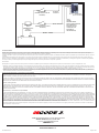
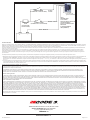
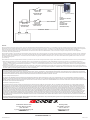
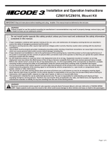
Operation:
After installing the system it is best to do a POWER-UP RESET the frst time to ensure that all heads are in sync. Touch BLUE wire to ground while applying power. Wait 5 seconds and then
BLUE to BLACK (or press and hold pattern select button if installed. Connect to power and hold for 5 seconds. The LED head will blink 1 time to indicate it is set for the old 8 pattern set, twice to indicate
the 16 pattern set.
Synchronization:
Page 4 of 4
RED - POSITIVE
SWITCH
(USER SUPPLIED)
IN-LINE FUSE
(USER SUPPLIED)
WHITE -
SWITCH
(USER SUPPLIED)
YELLOW -
(SYNC)
BLUE -
MOMENTARY TO
GROUND (FLASH
PATTERN SELECT)/
POSITIVE (DIM ON
WARNING PATTERN
ONLY)
BLACK - GROUND
+ -
POSITIVE
An ECCO SAFETY GROUP™ Brand
ECCOSAFETYGROUP.com
10986 North Warson Road, St. Louis, MO 63114 USA
Technical Service USA (314) 996-2800
CODE3ESG.com

¡IMPORTANTE!
¡Importante! Esta unidad es un dispositivo de seguridad y se debe conectar a su propia fuente de poder de fusibles separada para asegurar su
Instrucciones de instalación y
funcionamiento
HB12PAK SÉRIE
1. Para garantizar su propia seguridad y la de las personas a las que intenta proteger, es esencial una instalación correcta, combinada con la
formación de operador en el uso, cuidado y mantenimiento de los dispositivos de alerta de emergencia.
2. Tenga cuidado cuando manipule conexiones eléctricas con corriente.
3. Este producto debe estar conectado a tierra correctamente. Una conexión a tierra incorrecta o unas conexiones eléctricas cortocircuitadas
pueden provocar arcos de corriente alta, lo que puede ocasionar lesiones personales o daños graves en el vehículo, incluso un incendio.
4. La colocación e instalación adecuadas son vitales para el buen funcionamiento de este dispositivo de alarma. Instale este producto de forma
que permita un rendimiento óptimo del sistema y los controles estén situados de modo que el operador pueda alcanzarlos cómodamente y
manejar el sistema sin perder en ningún momento el contacto visual con la calzada.
5. No instale este producto ni coloque los cables en la zona de despliegue de un airbag. Si el equipo se monta o coloca en la zona de des-
pliegue de un airbag, el airbag perderá ecacia o el equipo puede salir despedido, lo cual puede causar lesiones graves o incluso mortales.
Consulte el manual del propietario del vehículo para conocer la zona de despliegue de los airbags. El usuario u operador son responsables
de determinar una posición de montaje adecuada que garantice la seguridad de todos los ocupantes del vehículo, y deben evitar zonas que
puedan provocar golpes en la cabeza.
6. Es responsabilidad del operador del vehículo asegurarse de que todas las características de este producto funcionan correctamente
durante su uso. Durante su uso, el operador del vehículo debe asegurarse de que no haya componentes del vehículo (como los maleteros o
puertas del habitáculo abiertos), personas, vehículos u otros obstáculos que bloqueen la señal de alarma.
7. El uso de este o cualquier otro dispositivo de alarma no garantiza que los conductores puedan o quieran observar o reaccionar a la señal de
alarma. Nunca dé por hecho que tiene prioridad de paso. Es responsabilidad enteramente suya asegurarse de que puede continuar de forma
segura antes de entrar en una intersección, conducir en sentido contrario, responder a una gran velocidad o caminar por los carriles de
tráco o cerca de ellos.
8. El uso de este equipo está destinado exclusivamente a personal autorizado. El usuario es responsable de conocer y acatar todas las leyes
vigentes relacionadas con dispositivos de señales de advertencia. Por lo tanto, el usuario debe comprobar todas las leyes y normativas de
ámbito metropolitano, regional, nacional y cualquier otro ámbito pertinente. El fabricante no asume responsabilidad alguna por pérdidas
derivadas del uso de este dispositivo de alarma.
No instale ni opere este producto de seguridad, a menos que haya leído y comprendido la información de
seguridad contenida en este manual.
Si no sigue las instrucciones del fabricante a la hora de instalar o usar el producto, pueden producirse daños materiales, y lesiones graves o
incluso mortales a aquellos que pretende proteger!
!
¡ADVERTENCIA!
Tamaño: 25,1 mm (0,99 pulg.) de diám. (solo cabezal de luz)
Tensión de entrada: 12-24 V CC
Consumo de corriente máximo:
Color único:
Color doble:
Especicaciones:
Potencia máxima:
Color único:
Color doble:
Rango de temperatura de funcionamiento: -40 °C a 70 °C
Lúmenes:
Ámbar doble: 130 lm
Azul doble: 39,1 lm
Rojo doble: 64,5 lm
Blanco doble: 99,7 lm
Ámbar único: 226,2 lm
Azul único: 49,4 lm
Rojo único: 84,32 lm
Rojo único: 84,32 lm

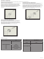
Montaje de cierre por torsión (Figura 3):
Localice y retire el enchufe macho de la bombilla del fabricante original
alrededor de la junta de goma. Inserte el cabezal de luz de cierre por torsión en
Figura 3
Montaje de la lámpara (Figura 1):
silicona RTV alrededor del cabezal LED para sellarlo. Fije el módulo del
controlador a un mazo de cables o una estructura de la carrocería cercanos.
Montaje en supercie (Figura 2):
los dos tornillos suministrados. Se debe utilizar sellador de silicona RTV
Figura 1
Figura 2
Conexión eléctrica:
Color único
ROJO POSITIVO
NEGRO NEGATIVO
AZUL
SELECCIÓN DE PATRÓN NEGATIVA / POSITIVO
(SOLO ATENUADO EN PATRÓN DE ADVERTEN-
CIA)
AMARILLO FUNCIÓN SINCRONIZADA
APLIQUE EL CABLE AZUL SOBRE EL CABLE
NEGRO
FUNCIÓN
0-1 SEG. SIGUIENTE PATRÓN
1-3 SEG. PATRÓN ANTERIOR
3-5 SEG. PATRÓN PREDETERMINADO DE FÁBRICA
5 SEG. ÚLTIMO PATRÓN
Color doble:
ROJO POSITIVO, COLORES 1 & 3
BLANCO POSITIVO, COLORES 2 & 4
ROJO & BLANCO POSITIVO, (COLORES 1 & 3) & (COLORES 2 & 4)
NEGRO NEGATIVO
AZUL
SELECCIÓN DE PATRÓN NEGATIVA / POSITIVO (SOLO AT-
ENUADO EN PATRÓN DE ADVERTENCIA)
AMARILLO FUNCIÓN SINCRONIZADA
APLIQUE EL CABLE AZUL SOBRE
EL CABLE NEGRO
FUNCIÓN
0-1 SEG. PATRÓN PRÓXIMO
1-3 SEG. PATRÓN ANTERIOR
3-5 SEG. PATRÓN PREDETERMINADO DE FÁBRICA
5 SEG. ÚLTIMO PATRÓN
Instalación y montaje:
Antes de la instalación, compruebe si los cabezales LED han sufrido daños durante el transporte. No utilice piezas dañadas o rotas.

Garantía limitada del fabricante y restricción de la responsabilidad:
limitada se extiende por sesenta (60) meses a partir de la fecha de compra.
EL DAÑO A LAS PIEZAS O LOS PRODUCTOS CAUSADO POR LA ALTERACIÓN, ACCIDENTE, ABUSO, MAL USO, NEGLIGENCIA, MODIFICACIONES NO AUTORIZADAS, FUEGO U OTRO PELIGRO;
INSTALACIÓN U OPERACIÓN INCORRECTAS; O NO REALIZAR EL MANTENIMIENTO DE ACUERDO CON LOS ROCEDIMIENTOS DE MANTENIMIENTO ESTABLECIDOS EN LAS INSTRUCCIONES DE
INSTALACIÓN Y DE OPERACIÓN DEL FABRICANTE ANULA ESTA Garantía LIMITADA.
Exclusión de otras garantías:
EL FABRICANTE NO OFRECE NINGUNA OTRA GARANTÍA, EXPRESA O IMPLÍCITA. LAS GARANTÍAS IMPLÍCITAS DE COMERCIABILIDAD, CALIDAD O IDONEIDAD PARA UN OBJETIVO PARTICULAR,
O QUE SURJAN DE UNA TRANSACCIÓN, USO O PRÁCTICA DE COMERCIO QUEDAN EXCLUIDAS POR MEDIO DE LA PRESENTE Y NO SERÁN VÁLIDAS PARA EL PRODUCTO, Y SE ANULAN
POR MEDIO DE LA PRESENTE, EXCEPTO EN LA MEDIDA EN QUE LO PROHÍBAN LAS LEYES VIGENTES. LAS DECLARACIONES VERBALES O REPRESENTACIONES SOBRE EL PRODUCTO NO
CONSTITUYEN GARANTÍAS.
Compensaciones y restricción de la responsabilidad:
LA ÚNICA RESPONSABILIDAD DEL FABRICANTE Y LA ÚNICA Y EXCLUSIVA COMPENSACIÓN DEL COMPRADOR EN VIRTUD DE UN CONTRATO, POR ILÍCITO CIVIL O SEGÚN CUALQUIER SU-
PUESTO EN CONTRA DEL FABRICANTE RESPECTO AL PRODUCTO Y SU USO SERÁ EL REEMPLAZO O LA REPARACIÓN DEL PRODUCTO, O EL REEMBOLSO DEL PRECIO DE COMPRA PAGADO
QUE HAYA PAGADO EL COMPRADOR POR EL PRODUCTO QUE NO CUMPLE CON LOS REQUISITOS. EN NINGÚN CASO LA RESPONSABILIDAD DEL FABRICANTE QUE SURJA DE ESTA GARANTÍA
LIMITADA O POR CUALQUIER OTRA RECLAMACIÓN RELACIONADA CON LOS PRODUCTOS DEL FABRICANTE EXCEDERÁ LA CANTIDAD QUE EL COMPRADOR PAGÓ POR EL PRODUCTO EN
EL MOMENTO DE LA COMPRA ORIGINAL. EN NINGÚN CASO EL FABRICANTE SERÁ RESPONSABLE POR LUCRO CESANTE, EL COSTO DE LA SUSTITUCIÓN DEL EQUIPO O LA MANO DE OBRA,
DAÑOS A LA PROPIEDAD U OTROS DAÑOS ESPECIALES, CONSECUENCIALES O INCIDENTALES QUE SE BASEN EN CUALQUIER RECLAMACIÓN POR INCUMPLIMIENTO DE CONTRATO, INSTA-
LACIÓN INAPROPIADA, NEGLIGENCIA O DE OTRO TIPO, INCLUSO SI SE LE HA INFORMADO AL FABRICANTE O A UN REPRESENTANTE DEL FABRICANTE SOBRE LA POSIBILIDAD DE QUE OCUR-
RAN TALES DAÑOS. EL FABRICANTE NO TENDRÁ NINGUNA OTRA OBLIGACIÓN O RESPONSABILIDAD CON RESPECTO AL PRODUCTO O SU VENTA, OPERACIÓN Y USO, Y EL FABRICANTE NO
ASUME NI AUTORIZA EL SUPUESTO DE CUALQUIER OTRA OBLIGACIÓN O RESPONSABILIDAD EN RELACIÓN CON DICHO PRODUCTO.
daños incidentales o consecuenciales.
920-0840-00 Rev. C
Funcionamiento:
a cambiar.
Sincronización:
Este dispositivo es capaz de sincronizar hasta 8 productos de CODE 3 compatibles siguiendo estos pasos. Este dispositivo se puede sincronizar dentro de un patrón de parpadeo de 1 a 63.
1. Establezca el patrón de parpadeo deseado en cada unidad de forma individual. Además, se recomienda encarecidamente utilizar el mismo patrón de parpadeo en todas las unidades para producir el patrón
demás unidades conectadas al cable de sincronización amarillo.
ROJO - POSITIVO
CAMBIAR
(SUMINISTRADO POR EL
USUARIO)
FUSIBLE EN
LÍNEA
(SUMINISTRADO
POR EL
USUARIO)
BLANCA -
POSITIVO
AMARILLO -
(Sincronización)
AZUL -
TIERRA
MOMENTÁNEA
(SELECCIONE PATRÓN
DE PARPADEO)/
POSITIVO (SOLO
ATENUADO EN
PATRÓN DE
ADVERTENCIA)
NEGRO - TIERRA
+ -
CAMBIAR
(SUMINISTRADO POR EL
USUARIO)
An ECCO SAFETY GROUP™ Brand
ECCOSAFETYGROUP.com
10986 North Warson Road, St. Louis, MO 63114 USA
Sevicio Técnico USA (314) 996-2800
CODE3ESG.com

Page 1 sur 3
IMPORTANT!
Importante!
Instructions d'installation et
d'utilisation
HB12PAK SÉRIES
1. Pour garantir votre sécurité et celle des autres, il est essentiel que le produit soit correctement installé et que l’opérateur soit formé à
l’utilisation, l’entretien et la maintenance des dispositifs d’avertissement d’urgence.
2. Manipulez les connexions électriques sous tension avec prudence.
3. Ce produit doit être correctement mis à la masse. Une mise à la masse inadéquate ou un court-circuit des connexions électriques peut
provoquer l’apparition d’un arc électrique haute tension, susceptible de causer des blessures corporelles ou des dommages graves sur le
véhicule, ainsi qu’un incendie.
4. Une installation et un positionnement corrects sont essentiels au bon fonctionnement de ce dispositif d’avertissement. Installez ce produit
de manière à optimiser les performances de sortie du système et de sorte que les commandes soient à portée de main de l’opérateur, an
qu’il puisse utiliser le système sans perdre le contact visuel avec la chaussée.
5. N’installez pas ce produit dans la zone de déploiement d’un airbag ; n’acheminez pas non plus de câbles dans cette zone. Tout équipement
monté ou situé dans la zone de déploiement d’un airbag est susceptible de réduire l’ecacité de cet airbag ou de devenir un projectile pou-
vant causer des blessures graves, voire mortelles. Reportez-vous au manuel d’utilisation du véhicule pour en savoir davantage sur la zone
de déploiement de l’airbag. Il incombe à l’utilisateur/à l’opérateur de dénir un emplacement de montage approprié assurant la sécurité
de tous les passagers à l’intérieur du véhicule, en évitant en particulier les zones d’impact potentiel de la tête.
6. Il incombe à l’opérateur du véhicule de s’assurer que toutes les fonctionnalités de ce produit fonctionnent correctement au cours de
l’utilisation. Lorsque le produit est en cours d’utilisation, l’opérateur du véhicule doit s’assurer que le signal d’avertissement n’est pas inhibé
par des composants du véhicule (comme un core ou des portes de compartiment ouverts), des personnes, des véhicules ou d’autres
éléments.
7. L’utilisation de ce dispositif d’avertissement ou de tout autre dispositif similaire ne garantit pas que tous les conducteurs observeront un
signal d’avertissement ou réagiront à ce signal. Ne prenez jamais la priorité pour acquise. Il est de votre responsabilité de vous assurer que
vous pouvez vous déplacer en toute sécurité avant de vous engager dans une intersection, de conduire en sens inverse de la circulation, de
réagir à une vitesse élevée et de marcher sur ou autour des voies de circulation.
8. Cet équipement est destiné uniquement au personnel autorisé. Il incombe à l’utilisateur de comprendre et de respecter toutes les lois rela-
tives aux dispositifs de signalisation d’avertissement. Par conséquent, l’utilisateur doit s’informer sur toutes les lois et réglementations en
vigueur dans la ville, la région et le pays où il se trouve. Le fabricant décline toute responsabilité en cas de perte découlant de l’utilisation de
ce dispositif d’avertissement.
N’installez pas et/ou n’utilisez pas ce produit de sécurité avant d’avoir lu et compris les consignes de
sécurité fournies.
Lisez toutes les instructions avant d’installer et d’utiliser le produit. Installateur : ce manuel doit être remis à l’utilisateur nal.
!
AVERTISSEMENT!
Consommation de courant maximale :
Unicolore :
Bicolore:
Caractéristiques:
Puissance maximale:
Unicolore :
Bicolore:
Lumens:
Orange bicolore - 130 lm
Bleu bicolore - 39,1 lm
Rouge bicolore - 64,5 lm
Blanc bicolore - 99,7 lm
Orange unicolore - 226,2 lm
Bleu unicolore - 49,4 lm
Rouge unicolore - 84,32 lm
Blanc unicolore - 209,8 lm

Installation et montage:
Montage à verrouillage rotatif (Figure 3):
s’arrête de tourner, puis retirez-la du culot. Notez la position des encoches de
rotatif dans le culot et faites-la tourner dans le sens des aiguilles d’une montre
Figure 3
Montage de la lampe (Figure 1):
25,4 mm (1”) des autres ampoules. Percez un trou de 25,4 mm (1”) dans le
autour de la tête de LED pour la sceller. Attachez le module conducteur à un
Surface de montage (Figure 2):
(1”) des autres objets. Percez un trou de 25,4 mm (1”) dans la carrosserie avec
de 25,4 mm (1”). Installez le cadre et le support à l’aide des deux vis fournies.
trous de vis.
Figure 1
Figure 2
Connexion électrique:
UNICOLORE
ROUGE POSITIF
NOIR NÉGATIF
BLEU
SÉLECTION DU MODE SUR NÉGATIF/POSI-
TIF (ATTÉNUATION EN MODE
D’AVERTISSEMENT UNIQUEMENT)
JAUNE FONCTION SYNCHRONISÉE
APPLIQUER LE CÂBLE BLEU SUR LE CÂBLE
NOIR
FONCTION
0 À 1 S. MODE SUIVANT
1 À 3 S. MODE PRÉCÉDENT
3 À 5 S. MODE PAR DÉFAUT D’USINE
5 S. DERNIER MODE
BICOLORE
ROUGE POSITIF, COULEURS 1 & 3
BLANC POSITIF, COULEURS 2 & 4
ROUGE ET BLANC POSITIF, (COULEURS 1 & 3) & (COULEURS 2 & 4)
NOIR NÉGATIF
BLEU
SÉLECTION DU MODE SUR NÉGATIF/POSITIF
(ATTÉNUATION EN MODE
D’AVERTISSEMENT UNIQUEMENT)
JAUNE FONCTION SYNCHRONISÉE
APPLIQUER LE CÂBLE BLEU SUR LE
CÂBLE NOIR
FONCTION
0 À 1 S. PROCHAIN MODE
1 À 3 S. MODE PRÉCÉDENT
3 À 5 S. MODE PAR DÉFAUT D’USINE
5 S. DERNIER MODE
Page 2 sur 3

Garantie limitée du fabricant et limitation de responsabilité :
soixante(60) mois à compter de la date d’achat.
LES DOMMAGES À DES PIÈCES OU À DES PRODUITS RÉSULTANT D’UNE ALTÉRATION, D’UN ACCIDENT, D’UN ABUS, D’UNE NÉGLIGENCE, DE MODIFICATIONS NON AUTORISÉES, D’UN
INCENDIE OU DE TOUT AUTRE DANGER ; DE L’INSTALLATION OU D’UNE UTILISATION INCORRECTE ; OU D’UN DÉFAUT D’ENTRETIEN CONFORME AUX PROCÉDURES DE MAINTENANCE
DÉCRITES DANS LES CONSIGNES D’INSTALLATION ET D’UTILISATION DU FABRICANT ANNULENT CETTE GARANTIE LIMITÉE.
Exclusion d’autres garanties :
LE FABRICANT N’ÉMET AUCUNE AUTRE GARANTIE, QU’ELLE SOIT EXPRESSE OU IMPLICITE. LES GARANTIES IMPLICITES DE QUALITÉ MARCHANDE, DE QUALITÉ OU D’ADAPTATION À UN
OBJECTIF PARTICULIER, OU DÉCOULANT D’UNE TRANSACTION, D’UN USAGE OU DE PRATIQUES COMMERCIALES, SONT EXCLUES PAR LES PRÉSENTES, NE S’APPLIQUERONT PAS AU
PRODUIT, ET SONT DÉCLINÉES PAR LES PRÉSENTES, EXCEPTÉ DANS LA MESURE INTERDITE PAR LA LÉGISLATION EN VIGUEUR. LES DÉCLARATIONS ORALES OU AUTRES DÉCLARATIONS
CONCERNANT LE PRODUIT NE CONSTITUENT PAS DES GARANTIES.
Recours et limitation de responsabilité :
LA SEULE RESPONSABILITÉ DU FABRICANT ET LE RECOURS EXCLUSIF DE L’ACHETEUR CONTRE LE FABRICANT, PAR CONTRAT, EN CAS DE DÉLIT (Y COMPRIS LA NÉGLIGENCE), OU SELON
TOUTE AUTRE THÉORIE, EN CE QUI CONCERNE LE PRODUIT ET SON UTILISATION, SE LIMITERONT, À LA DISCRÉTION DU FABRICANT, AU REMPLACEMENT OU À LA RÉPARATION DU PRODUIT,
OU AU REMBOURSEMENT DU PRIX D’ACHAT PAYÉ PAR L’ACHETEUR POUR LE PRODUIT NON CONFORME. EN AUCUN CAS LA RESPONSABILITÉ DU FABRICANT DÉCOULANT DE CETTE
GARANTIE LIMITÉE OU DE TOUTE AUTRE RÉCLAMATION RELATIVE AUX PRODUITS DU FABRICANT NE DÉPASSERA LE MONTANT PAYÉ PAR L’ACHETEUR POUR LE PRODUIT AU MOMENT
DE L’ACHAT INITIAL. EN AUCUN CAS LE FABRICANT NE POURRA ÊTRE TENU POUR RESPONSABLE DE LA PERTE DE PROFITS, DU COÛT DE L’ÉQUIPEMENT OU DE LA MAIN D’OEUVRE DE
REMPLACEMENT, DES DOMMAGES MATÉRIELS, OU D’AUTRES DOMMAGES SPÉCIAUX, CONSÉCUTIFS OU INCIDENTS EN SE BASANT SUR UNE RÉCLAMATION POUR RUPTURE DE CONTRAT,
INSTALLATION INAPPROPRIÉE, NÉGLIGENCE OU TOUTE AUTRE RÉCLAMATION, MÊME SI LE FABRICANT OU UN REPRÉSENTANT DU FABRICANT A ÉTÉ AVERTI DE LA POSSIBILITÉ DE TELS
DOMMAGES. LE FABRICANT N’A AUCUNE AUTRE OBLIGATION OU RESPONSABILITÉ EN CE QUI CONCERNE LE PRODUIT OU SA VENTE, SON FONCTIONNEMENT ET SON UTILISATION, ET LE
FABRICANT N’ASSUME NI N’AUTORISE EN AUCUN CAS L’HYPOTHÈSE D’UNE AUTRE OBLIGATION OU RESPONSABILITÉ EN RELATION AVEC CE PRODUIT.
920-0840-00 Rev. C
Fonctionnement:
Synchronisation:
ROUGE - POSITIF
FUSIBLE EN
LIGNE
(FOURNI PAR
LUTILISATEUR)
BLANC -
POSITIF
JAUNE -
( Fonction de
synchronisation)
BLEU
MOMENTANÉ
À LA MASSE
(SÉLECTION DU MODE DE
CLIGNOTEMENT)/
POSITIF (ATTÉNUATION
EN MODE
D'AVERTISSEMENT
UNIQUEMENT)
NOIR - NÉGATIF
+ -
COMMUTATEUR
(FOURNI PAR L'UTILISATEUR)
COMMUTATEUR
(FOURNI PAR L'UTILISATEUR)
Page 3 sur 3
An ECCO SAFETY GROUP™ Brand
ECCOSAFETYGROUP.com
10986 North Warson Road, St. Louis, MO 63114 USA
Service Technique USA (314) 996-2800
CODE3ESG.com

Seite 1 von 3
WICHTIG! Lesen Sie vor der Installation und Verwendung alle Anweisungen. Monteur: Diese Anleitung muss dem Endbenutzer zugestellt werden.
Wichtig! Dieses Gerät ist eine Sicherheitsvorrichtung und muss an eine separate, abgesicherte Stromversorgung angeschlossen werden, um den
weiteren Betrieb bei Ausfall eines anderen elektrischen Zubehörs zu gewährleisten.
Installations- und Bedienungsanleitung
HB12PAK SERIE
1. Eine ordnungsgemäße Installation sowie eine Bedienerschulung in Hinsicht auf die Verwendung, Pege und Wartung von Warnvorrichtun
gen sind unerlässlich, um Ihre Sicherheit und die Sicherheit der Personen, denen Sie helfen möchten, zu gewährleisten.
2. Gehen Sie bei der Arbeit mit stromführenden elektrischen Anschlüssen vorsichtig vor.
3. Dieses Produkt muss ordnungsgemäß geerdet werden. Eine unzureichende Erdung und/oder ein Kurzschluss der elektrischen Anschlüsse
können zu Hochstromlichtbögen führen, die Verletzungen und/oder schwere Schäden am Fahrzeug, einschließlich Fahrzeugbrand, verursa-
chen können.
4. Die richtige Platzierung und Installation sind für die Leistung der Warnvorrichtung von entscheidender Bedeutung. Installieren Sie dieses
Produkt so, dass die Ausgangsleistung des Systems maximiert wird und die Bedienelemente sich in Reichweite des Bedieners benden
damit er/sie das System bedienen kann, ohne den Blick von der Fahrbahn nehmen zu müssen.
5. Montieren Sie dieses Produkt nicht im Entfaltungsbereich eines Airbags und verlegen Sie dort auch keine Kabel. Geräte, die sich im
Entfaltungsbereich eines Airbags benden bzw. dort montiert sind, beeinträchtigen möglicherweise die Wirksamkeit des Airbags oder
können zu „Geschossen“ werden, die schwere Verletzungen oder den Tod verursachen können. Informationen zum Entfaltungsbereich des
Airbags nden Sie im Fahrerhandbuch des Fahrzeugs. Es liegt in der Verantwortung des Benutzers/Bedieners, einen geeigneten Montageort
festzulegen, um die Sicherheit aller Fahrzeuginsassen zu gewährleisten und insbesondere Bereiche zu vermeiden, in denen möglicherweise
Kopfverletzungen auftreten können.
6. Es liegt in der Verantwortung des Fahrers, sicherzustellen, dass während der Verwendung alle Funktionen dieses Produkts ordnungsgemäß
funktionieren. Der Fahrer muss während der Verwendung sicherstellen, dass das Warnsignal nicht durch Fahrzeugkomponenten (z. B. oene
Koerraumklappe oder Türen), Personen, Fahrzeuge oder andere Hindernisse blockiert wird.
7. Durch die Verwendung dieser oder anderer Warnvorrichtungen kann nicht gewährleistet werden, dass alle Verkehrsteilnehmer das
Warnsignal sehen oder darauf reagieren. Sehen Sie das Vorfahrtsrecht niemals als selbstverständlich an. Es liegt in Ihrer Verantwortung
sicherzustellen, dass keine Gefahr für Sie besteht, bevor Sie eine Kreuzung überqueren, entgegen der Verkehrsrichtung oder mit hoher
Geschwindigkeit fahren oder sich außerhalb des Fahrzeugs auf oder in der Nähe der Fahrspur bewegen.
8. Dieses Gerät darf nur von autorisiertem Personal verwendet werden. Der Benutzer ist dafür verantwortlich, alle Gesetze in Bezug auf
Warnsysteme zu verstehen und einzuhalten. Daher sollte der Benutzer alle geltenden Gesetzte und Vorschriften auf Stadt-, Landes- und
Bundesebene prüfen. Der Hersteller übernimmt keine Haftung für Verluste, die durch die Verwendung dieser Warnvorrichtung entstehen.
Installieren und/oder verwenden Sie dieses Sicherheitsprodukt nur, wenn Sie die Sicherheitsinformationen in dieser
Anleitung gelesen und verstanden haben.
Wenn Sie dieses Produkt nicht gemäß den Empfehlungen des Herstellers installieren oder verwenden, kann dies zu Sachschäden, schweren
Personenschäden und/oder zum Tod für Sie und die Personen, denen Sie helfen möchten, führen!
!
WARNUNG!
Größe: 25,1 mm (0,99”) Durchm. (nur Lampenkopf)
Eingangsspannung: 12–24 V DC
Maximale Stromaufnahme:
Einfarbig:
1,06 A (Rot, leuchtet kontinuierlich)
1,24 A (Blau, leuchtet kontinuierlich)
1,30 A (Bernstein, leuchtet kontinuierlich)
1,27 A (Weiß, leuchtet kontinuierlich)
Zweifarbig:
0,61 A (BW, Bernstein leuchtet kontinuierlich)
0,81 A (BW, Weiß leuchtet kontinuierlich)
0,59 A (BR, Rot und Blau leuchten
kontinuierlich)
Spezikationen:
Maximale Leistung:
Einfarbig:
13,57 W (Rot, leuchtet kontinuierlich)
15,87 W (Blau, leuchtet kontinuierlich)
16,64 W (Bernstein, leuchtet kontinuierlich)
16,26 W (Weiß, leuchtet kontinuierlich)
Zweifarbig:
7,81 W (BW, Bernstein leuchtet kontinuierlich)
10,37 W (BW, Weiß leuchtet kontinuierlich)
7,55 W (BR, Rot und Blau leuchten kontinuierlich)
Betriebstemperaturbereich: -40° bis 70 °C
Lumens:
Zweifach, Bernstein – 130 lm
Zweifach, Blau – 39,1 lm
Zweifach, Rot – 64,5 lm
Zweifach, Weiß – 99,7 lm
Einfach, Bernstein – 226,2 lm
Einfach, Blau – 49,4 lm
Einfach, Rot – 84,32 lm
Einfach, Weiß – 209,8 lm

Twist-Lock-Montage (Abbildung 3):
Finden und entfernen Sie den OEM-Glühlampenstecker, indem Sie ihn gegen
den Uhrzeigersinn bis zum Anschlag drehen, und ziehen Sie ihn aus der
Fassung. Beachten Sie die Positionen der Aussparungen für die Haltenocken.
Tragen Sie die RTV-Silikon-Dichtmasse um die Gummidichtung herum auf.
Führen Sie den Twist-Lock-Lampenkopf durch die Fassung, und drehen Sie ihn
im Uhrzeigersinn bis zum Anschlag.
Achten Sie darauf, dass der Lampenkopf fest in der Fassung sitzt.
Abbildung 3
Lampenmontage (Abbildung 1):
Wählen Sie eine Stelle im Lampengehäuse des Fahrzeugs, die mindestens 25,4
mm (1,0”) von vorhandenen Glühlampen entfernt ist. Bohren Sie mit einer
Montieren Sie den LED-Kopf in das Bohrloch, wie in Abbildung 1 dargestellt.
Verwenden Sie zur Abdichtung des LED-Kopfs RTV-Silikon. Befestigen Sie das
Treibermodul in unmittelbarer Nähe eines Kabelbaums oder der
Karosseriestruktur. Stellen Sie elektrische Verbindungen her, wie unten
beschrieben.
Oberächenmontage (Abbildung 2):
Wählen Sie eine Stelle in der Fahrzeugkarosserie, die mindestens 25,4 mm (1,0”
von anderen Objekten entfernt ist. Bohren Sie mit einer Lochsäge ein 24,
5-mm-Loch (1,0”) in die Karosserie. Verwenden Sie die Blendenverkleidung als
Schablone, markieren Sie die Positionen der Montagelöcher und bohren Sie diese
Verbindungen her, und setzen Sie den LED-Kopf in das 25,4-mm-Loch (1,0”) ein.
Montieren Sie die Blendenverkleidung und die Halterung mit den beiden
mitgelieferten Schrauben. Um die Befestigungs- und Schraubenlöcher herum
sollte RTV-Silikon-Dichtmasse aufgetragen werden.
Abbildung 1
Abbildung 2
Elektrische Verbindung:
EINFARBIG
ROT POSITIV
SCHWARZ NEGATIV
BLAU
MUSTERAUSWAHL NEGATIV/POSITIV
(NUR DIMMEN DES WARNMUSTERS)
GELB SYNCHRONISIERIERUNGS-FUNKTION
BLAUES UND SCHWARZES KABEL
ZUSAMMENFÜHREN
FUNKTION
0-1 SEK. NÄCHSTES MUSTER
1-3 SEK. VORHERIGES MUSTER
3-5 SEK. WERKSEITIGES STANDARDMUSTER
5 SEK. LETZTES MUSTER
ZWEIFARBIG
ROT POSITIV, FARBEN 1 & 3
WEISS POSITIV, FARBEN 2 & 4
ROT UND WEISS POSITIVE, (COLORS 1 & 3) & (COLORS 2 & 4)
SCHWARZ NEGATIV
BLAU
MUSTERAUSWAHL NEGATIV/POSITIV
(NUR DIMMEN DES WARNMUSTERS)
GELB SYNCHRONISIERIERUNGS-FUNKTION
BLAUES UND SCHWARZES KABEL
ZUSAMMENFÜHREN
FUNKTION
0-1 SEK. NÄCHSTES MUSTER
1-3 SEK. VORHERIGES MUSTER
3-5 SEK. WERKSEITIGES STANDARDMUSTER
5 SEK. LETZTES MUSTER
Seite 2 von 3
Installation und Montage:
Überprüfen Sie die LED-Köpfe vor der Montage auf Transportschäden. Verwenden Sie keine beschädigten Teile

Garantie gilt sechzig (60) Monate ab dem Zeitpunkt des Erwerbs.
BEI SCHÄDEN AN TEILEN ODER PRODUKTEN, DIE DURCH MANIPULATION, UNFALL, MISSBRAUCH, UNSACHGEMÄSSE VERWENDUNG, FAHRLÄSSIGKEIT, NICHT GENEHMIGTE VERÄNDERUN-
GEN, FEUER ODER SONSTIGE GEFAHR; UNSACHGEMÄSSE INSTALLATION ODER BEDIENUNG; ODER NICHTEINHALTUNG DER IN DEN VON DER HERSTELLER FESTGELEGTEN INSTALLATIONS-
UND BEDIENUNGSANWEISUNGEN FESTGELEGTEN WARTUNGSVERFAHREN IST DIESE BESCHRÄNKTE GARANTIE UNGÜLTIG.
Ausschluss sonstiger Garantieansprüche:
DER HERSTELLER ÜBERNIMMT KEINE DARÜBER HINAUSGEHENDEN GARANTIEN, WEDER AUSDRÜCKLICH NOCH STILLSCHWEIGEND. DIE STILLSCHWEIGENDEN GARANTIEN FÜR MARK-
TGÄNGIGKEIT, QUALITÄT ODER EIGNUNG FÜR EINEN BESTIMMTEN ZWECK; ODER DIE SICH AUS DEM REGELMÄSSIGEN GESCHÄFTSGANG, DER NUTZUNG ODER DES HANDELSBRAUCHS
ERGEBEN; WERDEN HIERMIT AUSGESCHLOSSEN UND GELTEN NICHT FÜR DAS PRODUKT, SOWEIT NACH ANWENDBAREM RECHT ZULÄSSIG. MÜNDLICHE AUSSAGEN ODER ZUSICHERUNGEN
ZUM PRODUKT STELLEN KEINE GARANTIEN DAR.
Rechtsbehelfe und Haftungsbeschränkung:
DIE ALLEINIGE HAFTUNG VON DER HERSTELLER UND DER AUSSCHLIESSLICHE RECHTSBEHELF DES KÄUFERS, OB AUF VERTRAGLICHER GRUNDLAGE, AUS UNERLAUBTER HANDLUNG
(EINSCHLIESSLICH FAHRLÄSSIGKEIT) ODER EINEM SONSTIGEN RECHTLICHEN GRUND GEGEN DER HERSTELLER IN HINSICHT AUF DAS PRODUKT UND SEINE VERWENDUNG BESTEHEN
NACH ERMESSEN VON DER HERSTELLER IM ERSATZ ODER IN DER REPARATUR DES PRODUKTES ODER IN DER RÜCKERSTATTUNG DES KAUFPREISES, DEN DER KÄUFER FÜR DAS NICHT
KONFORME PRODUKT BEZAHLT HAT. UNTER KEINEN UMSTÄNDEN ÜBERSTEIGT DIE AUS DIESER BESCHRÄNKTEN GARANTIE ODER EINEM ANDEREN ANSPRUCH IM ZUSAMMENHANG MIT
DEN PRODUKTEN VON DER HERSTELLER ENTSTEHENDE HAFTUNG VON DER HERSTELLER DEN KAUFPREIS DES PRODUKTES ZUM ZEITPUNKT DES URSPRÜNGLICHEN ERWERBS DURCH
DEN KÄUFER. UNTER KEINEN UMSTÄNDEN HAFTET DER HERSTELLER FÜR ENTGANGENE GEWINNE, KOSTEN FÜR ERSATZGERÄTE ODER ARBEITSAUFWAND, SACHSCHADEN, ODER
SONSTIGE SPEZIELLE SCHÄDEN, FOLGESCHÄDEN ODER BEILÄUFIGE SCHÄDEN BASIEREND AUF ANSPRÜCHEN AUFGRUND VON VERTRAGSVERLETZUNG, FEHLERHAFTER INSTALLATION,
FAHRLÄSSIGKEIT, ODER ANDEREN ANSPRÜCHEN, SELBST WENN DER HERSTELLER ODER EIN VERTRETER VON DER HERSTELLER AUF DIE MÖGLICHKEIT SOLCHER SCHÄDEN HINGEWI-
ESEN WURDE. DER HERSTELLER ÜBERNIMMT KEINE WEITERE VERPFLICHTUNG ODER HAFTUNG HINSICHTLICH DES PRODUKTES ODER SEINES VERKAUFS, SEINER BEDIENUNG UND
SEINER VERWENDUNG, UND DER HERSTELLER ÜBERNIMMT KEINE HAFTUNG UND GENEHMIGT KEINE ÜBERNAHME ANDERER VERPFLICHTUNGEN ODER HAFTUNGEN IM ZUSAMMENHANG
MIT DIESEM PRODUKT.
Diese beschränkte Garantie deniert bestimmte Rechte. Möglicherweise haben Sie andere Rechte, die je nach Rechtsprechung variieren. In einigen Rechtsprechungen ist der Ausschluss oder die
Beschränkung von Neben- oder Folgeschäden nicht zulässig.
920-0840-00 Rev. C
Betrieb:
Nach der Installation des Systems ist es am besten, beim ersten Mal EINSCHALTEN ZURÜCKSETZEN durchzuführen, um sicherzustellen, dass alle Lampenköpfe synchronisiert wurden. Verbinden Sie das
BLAUE Kabel mit dem schwarzen Massekabel und aktivieren Sie die Stromversorgung. Warten Sie 5 Sekunden, und lösen Sie dann das BLAUE Kabel. Alle Lampenköpfe werden auf Dauerlicht zurückgesetzt.
(Wenn Sie eine Taste zur Auswahl des Leuchtmusters eingerichtet haben, halten Sie die Musterauswahl gedrückt, und schalten Sie den Netzschalter EIN.) Um ein Leuchtmuster auszuwählen,
verbinden Sie das BLAUE Kabel mit dem schwarzen Massekabel, oder drücken Sie den Schalter für die Musterauswahl, um das Leuchtmuster zu steigern. Die Köpfe merken sich das ausgewählte
Leuchtmuster, bis es wieder gewechselt wird.
Wenn Sie dieses Produkt zur Synchronisierung mit einem älteren Produkt verwenden, das nur über Leuchtmuster 1 bis 8 verfügt, können Sie dieses Produkt so programmieren, dass die Liste der Leuchtmuster
begrenzt wird. Führen Sie die folgenden Schritte aus: Verbinden Sie das BLAUE Kabel mit dem SCHWARZEN (oder halten Sie die Taste zur Auswahl des Leuchtmusters gedrückt, falls vorhanden). Schließen
Sie das rote Kabel an die Stromversorgung an, und halten Sie die Taste 5 Sekunden lang gedrückt. Blinkt der LED-Kopf einmal, so ist er für den alten 8-Muster-Satz eingestellt, blinkt er zweimal, so ist er für
den 16-Muster-Satz eingestellt.
Synchronisierung:
Dieses Gerät kann bis zu acht kompatible CODE 3-Produkte synchronisieren, indem Sie wie nachfolgend beschrieben vorgehen. Dieses Gerät kann innerhalb der Leuchtmuster 1 bis 63 synchronisiert werden.
2. Verbinden Sie die gelben Synchronisierungskabel miteinander und prüfen Sie, ob die Einheiten wie erwartet synchron blinken. Wenn eine Einheit ein falsches Muster ausgibt, kann mit dem blauen Kabel zur
Auswahl des Leuchtmusters auf dieser einzelnen Einheit vor- oder zurückgeschaltet werden, bis das richtige Muster ausgewählt ist. HINWEIS: Dadurch wird nur das Muster in dieser Einheit geändert. Einheiten,
ROT - POSITIV
INLINE-SICHERUNG
(NICHT IM
LIEFERUMFANG
ENTHALTEN)
WEIß -
POSITIV
GELB -
(Synchronisiert)
BLAU -
KURZZEITIG GEGEN
MASSE
(LEUCHTMUSTERAU
SWAHL)/
POSITIV (NUR
DIMMEN DES
WARNMUSTERS)
SCHWARZ - MASSE
+ -
SCHALTER
(NICHT IM
LIEFERUMFANG
ENTHALTEN)
SCHALTER
(NICHT IM
LIEFERUMFANG
ENTHALTEN)
Seite 3 von 3
Riedweg 58-60,
Ulm, 89081, Germany
+49 731 935 210
CODE3ESG.co.uk
10986 North Warson Road
St. Louis, MO 63114 USA
(314) 996-2800
CODE3ESG.com
An ECCO SAFETY GROUP™ Brand
ECCOSAFETYGROUP.com
-
 1
1
-
 2
2
-
 3
3
-
 4
4
-
 5
5
-
 6
6
-
 7
7
-
 8
8
-
 9
9
-
 10
10
-
 11
11
-
 12
12
-
 13
13


dans d''autres langues
- English: Code 3 HB12PAK
- español: Code 3 HB12PAK
- Deutsch: Code 3 HB12PAK
Documents connexes
-
 Code 3 CD9215 Series Installation And Operation Instructions Manual
-
 Code 3 CD3794 Install Instructions
-
 Code 3 CD3974 Installation And Operation Instructions Manual
-
 Code 3 C5517 Install Instructions
-
 Code 3 CB7265 Series Installation And Operation Instructions Manual
-
 Code 3 CD5051VDL2 Install Instructions
-
 Code 3 CZ6015/16 Installation And Operation Instructions Manual
-
 Code 3 Emergency Systems 2021 Mode d'emploi


Autres documents
-
Ecco ED3511A Le manuel du propriétaire
-
-
Camco 55306 Manuel utilisateur
-
-
LIVARNO 383066 Le manuel du propriétaire
-
Federal Signal Police/Fire MircoPulse Ultra Manuel utilisateur
-
Baumer OADM 21I6481/S14F Mode d'emploi
-
-
Yamaha PLG150 Le manuel du propriétaire
-
Marantec PA3F Le manuel du propriétaire